EP2187353A2 - Procédé de visualisation de structures dans un corps, notamment dans le corps d'un patient - Google Patents
Procédé de visualisation de structures dans un corps, notamment dans le corps d'un patient Download PDFInfo
- Publication number
- EP2187353A2 EP2187353A2 EP09151074A EP09151074A EP2187353A2 EP 2187353 A2 EP2187353 A2 EP 2187353A2 EP 09151074 A EP09151074 A EP 09151074A EP 09151074 A EP09151074 A EP 09151074A EP 2187353 A2 EP2187353 A2 EP 2187353A2
- Authority
- EP
- European Patent Office
- Prior art keywords
- image data
- ray
- ray image
- values
- structures
- Prior art date
- Legal status (The legal status is an assumption and is not a legal conclusion. Google has not performed a legal analysis and makes no representation as to the accuracy of the status listed.)
- Granted
Links
Images

Classifications
-
- G—PHYSICS
- G06—COMPUTING OR CALCULATING; COUNTING
- G06T—IMAGE DATA PROCESSING OR GENERATION, IN GENERAL
- G06T12/00—Tomographic reconstruction from projections
- G06T12/30—Image post-processing, e.g. metal artefact correction
-
- G—PHYSICS
- G06—COMPUTING OR CALCULATING; COUNTING
- G06T—IMAGE DATA PROCESSING OR GENERATION, IN GENERAL
- G06T2211/00—Image generation
- G06T2211/40—Computed tomography
- G06T2211/404—Angiography
-
- G—PHYSICS
- G06—COMPUTING OR CALCULATING; COUNTING
- G06T—IMAGE DATA PROCESSING OR GENERATION, IN GENERAL
- G06T2211/00—Image generation
- G06T2211/40—Computed tomography
- G06T2211/412—Dynamic
-
- G—PHYSICS
- G06—COMPUTING OR CALCULATING; COUNTING
- G06T—IMAGE DATA PROCESSING OR GENERATION, IN GENERAL
- G06T2211/00—Image generation
- G06T2211/40—Computed tomography
- G06T2211/424—Iterative
Definitions
- the invention relates to a method of visualizing structures in a body, in particular involving the structures of parts, such as organs, in the body of a patient.
- the invention assumes that the patient's body is in an X-ray angiography system with a C-arm.
- a C-arm Such a system is characterized in that at one end of the C-arm, an X-ray source is arranged and at the other end of the C-arm, an X-ray detector is arranged.
- the C-arm encloses the patient table.
- the X-radiation from the X-ray source on the way to the X-ray detector penetrates the patient.
- the C-arm can be twisted as a whole and, on the other hand, it can be tilted around its body axis. This makes it possible to image the patient from almost any perspective two-dimensional.
- Such two-dimensional images are obtained in particular during operations and interventions, so that the attending physician can better orient himself during the execution of the intervention or operation on the basis of images of the patient.
- 3D image data record before the procedure on the patient with another image acquisition system and to include 2D X-ray images obtained by so-called registering, ie assigning structures in the images from the 3D image data set on the one hand and structures using the X-ray angiography system Obtaining a mapping protocol while referring to the X-ray angiographic system and referring to it.
- 2D X-ray image data sets obtained by the X-ray angiography system itself can also be used be used to obtain a total of a 3D X-ray image data set in which individual volume elements in the room gray values are assigned.
- a so-called rotation of a C-arm in an X-ray angiography system takes five to ten seconds. During this time, there is often a movement of the patient: Patients may breathe during a rotation of an X-ray C-arc, her heart beats in any case repeatedly.
- the individual 2D X-ray image data sets can then be assigned to the individual intervals of the heartbeat phase. For each interval, the recorded 2D X-ray images treated as the same heartbeat phase treated, so it is assumed in the images of each interval of a static. Interval reconstruction algo- rithms from computed tomography can then be used.
- a so-called motion field is calculated from the reconstructions at individual heart-phase intervals, that is, it is calculated which point in the body of the patient moves from which point in space to which other point in space.
- the procedure assumes that the heart cyclically returns to the starting position. This assumption is only partially correct.
- the typical local deviation lies in the size of the diameter of the coronary arteries.
- the problem is particularly acute in some heart patients, because their heart just has irregularities in the field.
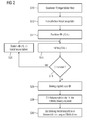
- the method of claim 1 begins by performing image acquisition steps by a C-arm X-ray angiography system, each at different successively traversed positions of that C-arm so that 2D X-ray image data sets are obtained in a train.
- Performing the image acquisition steps by the x-ray angiography system may be automatic or based on user input received from the x-ray angiography system.
- the method further defines properties of the structures to be visualized. This will allow a subsequent step, in which the 2D X-ray image data sets are prepared in such a way that the structures are highlighted in accordance with the definition in the illustration (ie in the representations of the 2D X-ray image data sets).
- An easy An example of this is a contrast enhancement, for example by filtering with an image filter adapted to the reconstruction problem, wherein, for example, it is defined as a structure that a certain contrast prevails between pixels spaced apart by a certain distance. It can be used in the preparation of the well-known technique of the so-called segmentation of the heart vessels, which in the article by TM Koller, G. Gerig, Gabor Székely, and D.
- the core idea of the invention is that subsequently values of a three-dimensional space allocated in the patient's body are obtained (derived, not mathematically derived) defined function, to each prepared 2D X-ray image data set. It should be noted here that the values are derived in each case from a prepared 2D X-ray image data record, taking into account data from a prepared 2D x-ray image data record which is subsequently obtained temporally adjacent.
- a level set is to be defined on the basis of these values, which defines the boundaries of the structures to be visualized in three-dimensional space.
- the next step is to perform the mapping of structures using the function in three-dimensional space to the derived values using a definition of a level set.
- the level set ultimately outputs binary information
- the derived values need not be binary, but are preferably not binary, and so just change from frame to frame from the captured sequence of 2D x-ray image sets a movement of the structures to be visualized are particularly well reflected.
- a screen representation of the structures can be generated on the basis of the assignment.
- gray values to volume elements have always been used in previous methods to make structures visible, in the present case at least in the first step this can be dispensed with, but the structures are defined on the basis of an abstractly defined function in three-dimensional space.
- the function carries no information except that it later allows you to define the surfaces of the structures based on the definition of the level set.
- the values of the functions can therefore be completely tailored to show the desired structures.
- Other information from the 2D X-ray image data sets can be omitted.
- a screen image can be derived from each 2D X-ray image data set, and it is possible to display a sequence of screen images in the sequence of the acquisition of respectively underlying 2D X-ray image data records. Then can play a movie that shows the movement of the coronary arteries in the order of recording the 2D X-ray images without having been averaged over several cycles. It is possible to achieve a sufficiently high quality of presentation, without the assumption that the coronary vessels undergo perfect cyclic movements, in which they always return exactly to the same place. The method is therefore particularly suitable for the depiction of the coronary arteries of patients with heart failure.
- the information about the surface of the structures is obtained solely on the basis of the derived values.
- An assignment of gray values is not required.
- the representation can be obtained on the basis of simple binary values, namely the ratio of a value of the function for a space point to the level quantity used as a criterion for defining a binary value for this space point, and then different gray values can be displayed in the screen on the two binary values or color values.
- the mapping then involves defining the contours of structures in three-dimensional space (namely, by defining the level set), and generating a screen display comprises that motion fields are derived from the contours for 2D X-ray image data sets in the order in which they are recorded, and that the image data from the 2D X-ray image data sets are then used to generate a 3D image data set with gray values to volume elements (ie for reconstruction), namely, the movement fields are taken into account.
- Help of the 3D image data record can then be calculated screen representations.
- the basic structure is first determined, ie the contours of the structures, and based on these contours, a calculation rule is then derived, as gray values for the three-dimensional space can be obtained from the individual gray values in the 2D X-ray image data sets.
- a calculation rule is then derived, as gray values for the three-dimensional space can be obtained from the individual gray values in the 2D X-ray image data sets.
- the fact that, in deriving the values, data is derived from a conditioned, subsequently subsequently obtained 2D X-ray image data may be reflected in the fact that the definition of the size implies that its calculation is done using values of the function of at least several and preferably all image data sets are carried out. Since the X-ray image data sets are obtained in a time sequence, the size may include a kind of temporal derivative.
- the method according to the invention makes it possible to image a moving object such as the coronary vessels with the aid of an X-ray angiography system which can only record 2D X-ray images with a relatively large time interval.
- a moving object such as the coronary vessels
- an X-ray angiography system which can only record 2D X-ray images with a relatively large time interval.
- image acquisition steps are performed by an X-ray angiography system to obtain 2D X-ray image data sets in a temporal sequence, e.g. on the basis of a user input, then the X-ray angiography system performs calculations and produces an image representation based on the calculations in which images are displayed in time sequence, wherein an image is displayed for the individual 2D X-ray image data sets and the order of the images is the same Order of obtaining the associated 2D X-ray image data sets is.
- the invention provides for the first time a method in which one type of film is played back on the basis of 2D X-ray images without averaging over several cycles.
- the calculations include deriving the values of the function defined in three-dimensional space according to the manner described above, in particular according to the method of claim 1.
- the method assumes that a catheter intervention is performed on a patient, whereby the patient is in the x-ray C-arm X-ray angiography system.
- the attending physician is interested in the coronary arteries. He uses the X-ray angiography system to obtain a plurality of X-ray images of the heart according to step S10, whereby the X-ray angiography system normally performs the image recording steps independently upon an input command.
- the X-ray C-arm is rotated around its central axis so that X-ray images are recorded at different angular positions during this movement.
- the time interval between the recording of the individual X-ray images should be between 10 and 20 ms, which is possible when taking a total of 400 X-ray images over an angular range of 200 °. Then the position of the coronary arteries hardly changes from X-ray image to X-ray image.
- step S12 This may involve simple filtering to increase the image contrast, preferably the method of segmentation according to Koller et al., Frangi et al and according to Krissian et al., See the above-cited articles of these authors.
- step S12 may be part of the acquisition of the X-ray images, ie implicitly by the X-ray detector of the X-ray angiography system on the basis of its properties, which may be optimized for the presentation of coronary vessels.
- ⁇ ( x , k) is determined.
- x is a point in real space, wherein the real space can be limited to the volume of space occupied by the patient.
- k represents the number of the respective X-ray image in the chronological order of its recording and corresponds to the time.
- the function ⁇ has the task of indicating the affiliation or non-membership of spatial points, defined for the individual x-ray images, for the coronary vessels.
- ⁇ ( x ) ⁇ 0 if the point in space x lies within a coronary vessel at the time the image k is taken.
- the value ⁇ ( x, k) is greater than 0 if the point in space is in any case outside the coronary vessels, and it is exactly 0 when it lies on the surface of a coronary vessel.
- a size E is calculated in step S16.
- the quantity E is intended to reflect to what extent an assignment of values to ⁇ ( x, k) in three-dimensional space deviates from reality in accordance with the X-ray image.
- the error variable E is composed of four sub-quantities E 1 , E 2 , E 3 and E 4 .
- E 1 is a fractional quantity representing that, due to the assignment of values to ⁇ , space dots are not assigned to a coronary vessel even though these space dots are imaged on a point in the X-ray image showing a coronary vessel after highlighting the coronary vessels in step S12.
- Partial size E 2 again shows how, due to the assignment of values to ⁇ , coronary vessels are erroneously provided in three-dimensional space, where due to the X-ray image none should be.
- the spatial variation of the size ⁇ is indicated by the size E 3
- the part size E 4 is here Measure for the temporal change from X-ray image to X-ray image.
- E 1 includes a constant factor C 1 and includes a sum over the X-ray images k. For each X-ray image, an integral over all X-ray pixels p is calculated, that is over the surface of the X-ray detector. For every point p the intensity I k ( p) is defined. This is multiplied in the integrand with the Heavisidefunktion of the following size:
- the totality X k ( p ) is considered, which includes all the points in space which lie on the way from the X-ray source to the point P from the X-ray detector.
- X k ( p ) is thus the totality of the points on the projection beam.
- the minimum of ⁇ ( x , k ) is determined for all spatial points x lying on this ray, if necessary there are several minima. If the minimum is greater than 0, the Heavisidefunktion H gives the value 1. Therefore, the integrand gives a contribution in the amount of I k ( p ).
- the intensity of such a spatial point in the subset E 1 is weighted if no coronary vessel is located on the beam from the X-ray source to this detector point according to the value assignment to ⁇ .
- I has a value greater than 0, and this just then contributes to the error size if, according to the definition of ⁇ , no coronary vessel would lie on the ray path to the detector point p .
- the greater the number of detector points p the greater will be E 1 Show the coronary vessel to which, according to the assigned values ⁇ , no coronary vessel would belong in three-dimensional space.
- the size E 2 is calculated analogously from a constant factor C 2 times the sum across all X-ray images. For each X-ray image, an integral is calculated, in the present case a volume integral over the spatial points x .
- p k (x) the point on the x-ray detector on which the spatial point x is projected.
- the error size E should be as small as possible.
- step S18 it is checked if E is minimum, and unless this is the case, the value assignment for ⁇ is changed in step S20.
- the technique of known variation methods for computer calculations of suitable discretized form is used.
- ⁇ is changed for each x and every k by a value that depends on E, eg a derivative of E.
- the Heavisidefunktion can be replaced by a function with a constant derivative such as an arctangent function.
- the error quantity is again determined in step S16 and checked again in step S18 whether E is minimal according to a predetermined criterion. If an abort criterion is satisfied, which is to be regarded as minimal according to E, the value assignments for ⁇ reflect the real spatial structures of the coronary vessels of the patient.
- ⁇ 0 is the definition of the surface of the coronary arteries by means of a level set. The ratio of ⁇ to this, ie ⁇ ⁇ 0 or ⁇ > 0, determines the membership of spatial points to the coronary vessels.
- step S22 a binary assignment of a gray value using ⁇ to individual volume elements is carried out, for example, volume elements in whose area a coronary vessel is located, pure white is assigned and volume elements located outside the coronary vessels are assigned pure black. Due to the assignment of the binary gray value to the volume elements either by the so-called volume rendering or by re-projection, but now with free, arbitrary viewing angle, then a two-dimensional representation of the coronary vessels on the screen in step S24 is possible. Such a presentation is completely sufficient for the purposes of the doctor: It is shown where in the room are coronary vessels and where not.
- the representation can be given in the form of a film in which the coronary vessels in each image are shown in the position in which one of the x-ray images is located, the film then reproducing the time sequence of the x-ray images, so that the treating physician uses the Movement of the illustrated structures can capture the movement of the coronary arteries.
- a motion field is calculated.
- the field of motion reflects how individual points on the surface of the coronary vessels have moved in three-dimensional space from X-ray image to X-ray image. Then you can link to known techniques that use motion fields. Once motion fields are known, a 3D reconstruction can be calculated. It is also possible to obtain 3D reconstructions from X-ray images taken in different heartbeat phases.
- Step S28 calculates a 3D reconstruction of the X-ray images obtained in step S10 using the motion fields. Unlike the method, based on FIG. 1 has been explained, the gray values of the X-ray images are thus used in order to assign gray values to volume elements in three-dimensional space. Then it is possible in step S30 to give a representation of the coronary vessels in a gray value representation on the screen. If, in step S28, all images are combined into a single 3D reconstruction, a single high-contrast image is obtained for a selected perspective. In step S28, a separate 3D reconstruction can also be calculated for each of the images; then, in step S30, a movie may be displayed in the order of recording the X-ray images based on the associated 3D reconstructions.
- the invention uses a purely abstractly defined function ⁇ ( x , k) in order to be able to assign structures to volume elements in three-dimensional space. It can then be given a representation in which as based on FIG. 1 does not explain any longer the originally obtained gray values. In the same way, the gray values can be used as well, as with FIG. 2 explains; but then the determination of the actual structures is preceded by assignment of values to the size ⁇ of the reconstruction.
Landscapes
- Physics & Mathematics (AREA)
- General Physics & Mathematics (AREA)
- Engineering & Computer Science (AREA)
- Theoretical Computer Science (AREA)
- Apparatus For Radiation Diagnosis (AREA)
- Image Processing (AREA)
Priority Applications (1)
| Application Number | Priority Date | Filing Date | Title |
|---|---|---|---|
| EP09151074A EP2187353B1 (fr) | 2008-11-10 | 2009-01-22 | Procédé de visualisation de structures dans un corps, notamment dans le corps d'un patient |
Applications Claiming Priority (3)
| Application Number | Priority Date | Filing Date | Title |
|---|---|---|---|
| EP08019641 | 2008-11-10 | ||
| EP08019642 | 2008-11-10 | ||
| EP09151074A EP2187353B1 (fr) | 2008-11-10 | 2009-01-22 | Procédé de visualisation de structures dans un corps, notamment dans le corps d'un patient |
Publications (3)
| Publication Number | Publication Date |
|---|---|
| EP2187353A2 true EP2187353A2 (fr) | 2010-05-19 |
| EP2187353A3 EP2187353A3 (fr) | 2010-06-23 |
| EP2187353B1 EP2187353B1 (fr) | 2011-10-19 |
Family
ID=40383800
Family Applications (1)
| Application Number | Title | Priority Date | Filing Date |
|---|---|---|---|
| EP09151074A Not-in-force EP2187353B1 (fr) | 2008-11-10 | 2009-01-22 | Procédé de visualisation de structures dans un corps, notamment dans le corps d'un patient |
Country Status (2)
| Country | Link |
|---|---|
| EP (1) | EP2187353B1 (fr) |
| AT (1) | ATE529839T1 (fr) |
Cited By (1)
| Publication number | Priority date | Publication date | Assignee | Title |
|---|---|---|---|---|
| US9675304B2 (en) | 2011-06-27 | 2017-06-13 | Koninklijke Philips N.V. | Live 3D angiogram using registration of a surgical tool curve to an X-ray image |
Citations (1)
| Publication number | Priority date | Publication date | Assignee | Title |
|---|---|---|---|---|
| US20060133564A1 (en) | 2004-12-21 | 2006-06-22 | David Langan | Method and apparatus for correcting motion in image reconstruction |
-
2009
- 2009-01-22 AT AT09151074T patent/ATE529839T1/de active
- 2009-01-22 EP EP09151074A patent/EP2187353B1/fr not_active Not-in-force
Patent Citations (1)
| Publication number | Priority date | Publication date | Assignee | Title |
|---|---|---|---|---|
| US20060133564A1 (en) | 2004-12-21 | 2006-06-22 | David Langan | Method and apparatus for correcting motion in image reconstruction |
Non-Patent Citations (8)
| Title |
|---|
| ALEJANDRO F. FRANGI; WIRO J. NIESSEN; KOEN L. VINCKEN; MAX A. VIERGEVER: "Proc. Int'l Conf. Med. Image Computing and Computer Assisted Intervention (MICCAI)", vol. 1496, SPRINGER, article "Multiscale vessel enhancement filtering", pages: 130 - 137 |
| GÜNTER LAURITSCH; JAN BOESE; LARS WIGSTRÖM; HERBERT KENNETH; REBECCA FAHRIG: "Towards cardiac C-arm computed tomography", IEEE TRANS. MED. IMAG., vol. 25, no. 7, 2006, pages 922 - 934 |
| KARL KRISSIAN; GREGOIRE MALANDAIN; NICHOLAS AYACHE; REGIS VAILLANT; YVES TROUSSET: "Model-based detection of tubular structures in 3D images", J. COMP. VIS. AND IMG. UNDERSTANDING, vol. 80, no. 2, 2000, pages 130 - 171, Retrieved from the Internet <URL:http: //dx.doi.org/10. 1006/cviu.2000.0866> |
| M. STYNER ET AL.: "Efficient segmentation of 3D fluoroskopic datasets from mobile C-arm", PROCEEDINGS OF THE SPIE - THE INTERNATIONAL SOCIETY FOR OPTICAL ENGINEERING, SPIE, US, vol. 5370, no. 1, 16 February 2004 (2004-02-16), pages 1667 - 1678 |
| MARCUS PRÜMMER; LARS WIGSTROEM; JOACHIM HORNEGGER; JAN BOESE; GUENTER LAURITSCH; NORBERT STROBEL; REBECCA FAHRIG: "Nuclear Science Symposium, Medical Imaging Conference", November 2006, SPRINGER, article "Cardiac C-arm CT: Efficient motion correction for 4D-FBP", pages: 1 - 20 |
| QI SU ET AL.: "A Semi-Automatic Clustering-Based Level Set Method for Segmentation of Endocardium from MSCT Images", ENGINEERING IN MEDICINE AND BIOLOGY SOCIETY, 2007. EMBS 2007, 29' ANNUAL INTERNATIONAL CONFERENCE OF THE IEEE, IEEE, 22 August 2007 (2007-08-22), pages 6023 - 6026 |
| T. KOHLBERGER ET AL.: "MEDICAL IMAGE COMPUTING AND COMPUTER-ASSISTED INTERVENTION - MIC CAI 2006 LECTURE NOTES IN COMPUTER SCIENCES", 1 January 2006, SPRINGER, article "4D shape Priors for a Level Set Segmentation of the Left Myocardium in SPECT Sequences", pages: 92 - 100 |
| T.M. KOLLER; G. GERIG; GABOR SZEKELY; D. DETT WILER: "Multiscale detection of curvilinear structures in 2-D und 3-D image data", PROC. INT'L CONF. COMP. VIS (ICCV), June 1995 (1995-06-01), pages 864 - 869, Retrieved from the Internet <URL:http://dx.doi.org/10.1109/ICCV. 1995. 466846> |
Cited By (1)
| Publication number | Priority date | Publication date | Assignee | Title |
|---|---|---|---|---|
| US9675304B2 (en) | 2011-06-27 | 2017-06-13 | Koninklijke Philips N.V. | Live 3D angiogram using registration of a surgical tool curve to an X-ray image |
Also Published As
| Publication number | Publication date |
|---|---|
| ATE529839T1 (de) | 2011-11-15 |
| EP2187353A3 (fr) | 2010-06-23 |
| EP2187353B1 (fr) | 2011-10-19 |
Similar Documents
| Publication | Publication Date | Title |
|---|---|---|
| DE602004002939T2 (de) | Methode zur dreidimensionalen modellierung von rohrförmigen strukturen | |
| DE102006045423B4 (de) | 07.09.07Verfahren zur Nachbearbeitung eines dreidimensionalen Bilddatensatzes einer Gefäßstruktur | |
| EP1114615B1 (fr) | Dispositif pour la représentation de l'évolution temporelle du débit sanguin | |
| DE102005027963B3 (de) | Verfahren und Vorrichtung zur Rekonstruktion eines 3D-Bilddatensatzes eines bewegten Objektes | |
| DE102012207629B4 (de) | CT-Bildrekonstruktion im erweiterten Messfeld | |
| DE102011087337B4 (de) | Verfahren zur Rekonstruktion eines zweidimensionale virtuelle Röntgenbilder enthaltenden Rekonstruktionsdatensatzes | |
| DE10129631A1 (de) | Verfahren zur Rekonstruktion eines hoch aufgelösten 3D-Bildes | |
| DE10100572A1 (de) | Verfahren zur Darstellung des Blutflusses in einem Gefäßbaum | |
| DE102009051384A1 (de) | Strahlaufhärtungskorrektur für CT-Perfusionsmessungen | |
| DE102009014723A1 (de) | Kontrastabhängige Regularisierungsstärke bei der iterativen Rekonstruktion von CT-Bildern | |
| DE102011083647A1 (de) | Verfahren, Rechensystem und CT-System zur Erzeugung eines bewegungskompensierten CT-Bilddatensatzes eines sich teilweise und zyklisch bewegenden Untersuchungsobjektes | |
| DE102012209410A1 (de) | Ermittlung einer patientenspezifischen Kontrastmittel-Impulsantwortfunktion | |
| DE102010034099B4 (de) | Iterative Bildfilterung mit anisotropem Rauschmodell für ein CT-Bild | |
| DE102016219887A1 (de) | Verfahren und System zur Nutzung von Messdaten | |
| DE102012104599A1 (de) | Verfahren und System zur Rekonstruktion tomografischer Bilder | |
| DE102008048045A1 (de) | Verfahren zur Erzeugung von computertomographischen Bilddatensätzen eines Patienten in der Herz-CT bei einer Perfusionskontrolle unter Kontrastmittelapplikation | |
| DE102010013360B4 (de) | Verfahren zur Rekonstruktion von Bilddaten eines zyklisch sich bewegenden Untersuchungsobjektes | |
| DE102007045313B4 (de) | Verfahren zur getrennten dreidimensionalen Darstellung von Arterien und Venen in einem Untersuchungsobjekt | |
| DE102008038357B3 (de) | Verfahren zur Erzeugung von 2D-Schnittbildern aus 3D-Projektionsdaten, die mittels eines CT-Systems von einem metallische Anteile enthaltenden Untersuchungsobjekt erfasst wurden | |
| DE102009007236A1 (de) | CT-Bildrekonstruktion eines sich bewegenden Untersuchungsobjektes | |
| DE102009021521B4 (de) | Verfahren zur bewegungskompensierten Rekonstruktion eines dreidimensionalen Bilddatensatzes und Röntgeneinrichtung | |
| EP2187353B1 (fr) | Procédé de visualisation de structures dans un corps, notamment dans le corps d'un patient | |
| DE102006045721A1 (de) | Verfahren zur Erzeugung tomographischer Aufnahmen von einem teilweise zyklisch bewegten Untersuchungsobjekt | |
| DE102010040944A1 (de) | Verfahren zur Bestimmung hämodynamischer Flussparameter von Blutgefäßen mit angiographischen CT-Bilddaten und CT-System | |
| DE102015202264B4 (de) | Korrektur von Bewegungsartefakten bei der CT-Bildgebung |
Legal Events
| Date | Code | Title | Description |
|---|---|---|---|
| PUAI | Public reference made under article 153(3) epc to a published international application that has entered the european phase |
Free format text: ORIGINAL CODE: 0009012 |
|
| AK | Designated contracting states |
Kind code of ref document: A2 Designated state(s): AT BE BG CH CY CZ DE DK EE ES FI FR GB GR HR HU IE IS IT LI LT LU LV MC MK MT NL NO PL PT RO SE SI SK TR |
|
| AX | Request for extension of the european patent |
Extension state: AL BA RS |
|
| PUAL | Search report despatched |
Free format text: ORIGINAL CODE: 0009013 |
|
| AK | Designated contracting states |
Kind code of ref document: A3 Designated state(s): AT BE BG CH CY CZ DE DK EE ES FI FR GB GR HR HU IE IS IT LI LT LU LV MC MK MT NL NO PL PT RO SE SI SK TR |
|
| AX | Request for extension of the european patent |
Extension state: AL BA RS |
|
| 17P | Request for examination filed |
Effective date: 20101018 |
|
| 17Q | First examination report despatched |
Effective date: 20101215 |
|
| AKX | Designation fees paid |
Designated state(s): AT BE BG CH CY CZ DE DK EE ES FI FR GB GR HR HU IE IS IT LI LT LU LV MC MK MT NL NO PL PT RO SE SI SK TR |
|
| GRAP | Despatch of communication of intention to grant a patent |
Free format text: ORIGINAL CODE: EPIDOSNIGR1 |
|
| GRAS | Grant fee paid |
Free format text: ORIGINAL CODE: EPIDOSNIGR3 |
|
| GRAA | (expected) grant |
Free format text: ORIGINAL CODE: 0009210 |
|
| AK | Designated contracting states |
Kind code of ref document: B1 Designated state(s): AT BE BG CH CY CZ DE DK EE ES FI FR GB GR HR HU IE IS IT LI LT LU LV MC MK MT NL NO PL PT RO SE SI SK TR |
|
| REG | Reference to a national code |
Ref country code: GB Ref legal event code: FG4D Free format text: NOT ENGLISH |
|
| REG | Reference to a national code |
Ref country code: CH Ref legal event code: EP |
|
| REG | Reference to a national code |
Ref country code: IE Ref legal event code: FG4D |
|
| REG | Reference to a national code |
Ref country code: DE Ref legal event code: R096 Ref document number: 502009001625 Country of ref document: DE Effective date: 20120119 |
|
| REG | Reference to a national code |
Ref country code: NL Ref legal event code: VDEP Effective date: 20111019 |
|
| LTIE | Lt: invalidation of european patent or patent extension |
Effective date: 20111019 |
|
| PG25 | Lapsed in a contracting state [announced via postgrant information from national office to epo] |
Ref country code: IS Free format text: LAPSE BECAUSE OF FAILURE TO SUBMIT A TRANSLATION OF THE DESCRIPTION OR TO PAY THE FEE WITHIN THE PRESCRIBED TIME-LIMIT Effective date: 20120219 Ref country code: NO Free format text: LAPSE BECAUSE OF FAILURE TO SUBMIT A TRANSLATION OF THE DESCRIPTION OR TO PAY THE FEE WITHIN THE PRESCRIBED TIME-LIMIT Effective date: 20120119 Ref country code: LT Free format text: LAPSE BECAUSE OF FAILURE TO SUBMIT A TRANSLATION OF THE DESCRIPTION OR TO PAY THE FEE WITHIN THE PRESCRIBED TIME-LIMIT Effective date: 20111019 |
|
| REG | Reference to a national code |
Ref country code: IE Ref legal event code: FD4D |
|
| PG25 | Lapsed in a contracting state [announced via postgrant information from national office to epo] |
Ref country code: SI Free format text: LAPSE BECAUSE OF FAILURE TO SUBMIT A TRANSLATION OF THE DESCRIPTION OR TO PAY THE FEE WITHIN THE PRESCRIBED TIME-LIMIT Effective date: 20111019 Ref country code: PT Free format text: LAPSE BECAUSE OF FAILURE TO SUBMIT A TRANSLATION OF THE DESCRIPTION OR TO PAY THE FEE WITHIN THE PRESCRIBED TIME-LIMIT Effective date: 20120220 Ref country code: GR Free format text: LAPSE BECAUSE OF FAILURE TO SUBMIT A TRANSLATION OF THE DESCRIPTION OR TO PAY THE FEE WITHIN THE PRESCRIBED TIME-LIMIT Effective date: 20120120 Ref country code: NL Free format text: LAPSE BECAUSE OF FAILURE TO SUBMIT A TRANSLATION OF THE DESCRIPTION OR TO PAY THE FEE WITHIN THE PRESCRIBED TIME-LIMIT Effective date: 20111019 Ref country code: SE Free format text: LAPSE BECAUSE OF FAILURE TO SUBMIT A TRANSLATION OF THE DESCRIPTION OR TO PAY THE FEE WITHIN THE PRESCRIBED TIME-LIMIT Effective date: 20111019 Ref country code: LV Free format text: LAPSE BECAUSE OF FAILURE TO SUBMIT A TRANSLATION OF THE DESCRIPTION OR TO PAY THE FEE WITHIN THE PRESCRIBED TIME-LIMIT Effective date: 20111019 Ref country code: HR Free format text: LAPSE BECAUSE OF FAILURE TO SUBMIT A TRANSLATION OF THE DESCRIPTION OR TO PAY THE FEE WITHIN THE PRESCRIBED TIME-LIMIT Effective date: 20111019 |
|
| PG25 | Lapsed in a contracting state [announced via postgrant information from national office to epo] |
Ref country code: CY Free format text: LAPSE BECAUSE OF FAILURE TO SUBMIT A TRANSLATION OF THE DESCRIPTION OR TO PAY THE FEE WITHIN THE PRESCRIBED TIME-LIMIT Effective date: 20111019 |
|
| BERE | Be: lapsed |
Owner name: SIEMENS A.G. Effective date: 20120131 |
|
| PG25 | Lapsed in a contracting state [announced via postgrant information from national office to epo] |
Ref country code: BG Free format text: LAPSE BECAUSE OF FAILURE TO SUBMIT A TRANSLATION OF THE DESCRIPTION OR TO PAY THE FEE WITHIN THE PRESCRIBED TIME-LIMIT Effective date: 20120119 Ref country code: EE Free format text: LAPSE BECAUSE OF FAILURE TO SUBMIT A TRANSLATION OF THE DESCRIPTION OR TO PAY THE FEE WITHIN THE PRESCRIBED TIME-LIMIT Effective date: 20111019 Ref country code: SK Free format text: LAPSE BECAUSE OF FAILURE TO SUBMIT A TRANSLATION OF THE DESCRIPTION OR TO PAY THE FEE WITHIN THE PRESCRIBED TIME-LIMIT Effective date: 20111019 Ref country code: DK Free format text: LAPSE BECAUSE OF FAILURE TO SUBMIT A TRANSLATION OF THE DESCRIPTION OR TO PAY THE FEE WITHIN THE PRESCRIBED TIME-LIMIT Effective date: 20111019 Ref country code: CZ Free format text: LAPSE BECAUSE OF FAILURE TO SUBMIT A TRANSLATION OF THE DESCRIPTION OR TO PAY THE FEE WITHIN THE PRESCRIBED TIME-LIMIT Effective date: 20111019 Ref country code: IE Free format text: LAPSE BECAUSE OF FAILURE TO SUBMIT A TRANSLATION OF THE DESCRIPTION OR TO PAY THE FEE WITHIN THE PRESCRIBED TIME-LIMIT Effective date: 20111019 |
|
| PLBE | No opposition filed within time limit |
Free format text: ORIGINAL CODE: 0009261 |
|
| STAA | Information on the status of an ep patent application or granted ep patent |
Free format text: STATUS: NO OPPOSITION FILED WITHIN TIME LIMIT |
|
| PG25 | Lapsed in a contracting state [announced via postgrant information from national office to epo] |
Ref country code: IT Free format text: LAPSE BECAUSE OF FAILURE TO SUBMIT A TRANSLATION OF THE DESCRIPTION OR TO PAY THE FEE WITHIN THE PRESCRIBED TIME-LIMIT Effective date: 20111019 Ref country code: RO Free format text: LAPSE BECAUSE OF FAILURE TO SUBMIT A TRANSLATION OF THE DESCRIPTION OR TO PAY THE FEE WITHIN THE PRESCRIBED TIME-LIMIT Effective date: 20111019 Ref country code: PL Free format text: LAPSE BECAUSE OF FAILURE TO SUBMIT A TRANSLATION OF THE DESCRIPTION OR TO PAY THE FEE WITHIN THE PRESCRIBED TIME-LIMIT Effective date: 20111019 Ref country code: MC Free format text: LAPSE BECAUSE OF NON-PAYMENT OF DUE FEES Effective date: 20120131 |
|
| 26N | No opposition filed |
Effective date: 20120720 |
|
| REG | Reference to a national code |
Ref country code: FR Ref legal event code: ST Effective date: 20120928 |
|
| REG | Reference to a national code |
Ref country code: DE Ref legal event code: R097 Ref document number: 502009001625 Country of ref document: DE Effective date: 20120720 |
|
| PG25 | Lapsed in a contracting state [announced via postgrant information from national office to epo] |
Ref country code: BE Free format text: LAPSE BECAUSE OF NON-PAYMENT OF DUE FEES Effective date: 20120131 Ref country code: FR Free format text: LAPSE BECAUSE OF NON-PAYMENT OF DUE FEES Effective date: 20120131 |
|
| PG25 | Lapsed in a contracting state [announced via postgrant information from national office to epo] |
Ref country code: MK Free format text: LAPSE BECAUSE OF FAILURE TO SUBMIT A TRANSLATION OF THE DESCRIPTION OR TO PAY THE FEE WITHIN THE PRESCRIBED TIME-LIMIT Effective date: 20111019 |
|
| PG25 | Lapsed in a contracting state [announced via postgrant information from national office to epo] |
Ref country code: ES Free format text: LAPSE BECAUSE OF FAILURE TO SUBMIT A TRANSLATION OF THE DESCRIPTION OR TO PAY THE FEE WITHIN THE PRESCRIBED TIME-LIMIT Effective date: 20120130 |
|
| PG25 | Lapsed in a contracting state [announced via postgrant information from national office to epo] |
Ref country code: FI Free format text: LAPSE BECAUSE OF FAILURE TO SUBMIT A TRANSLATION OF THE DESCRIPTION OR TO PAY THE FEE WITHIN THE PRESCRIBED TIME-LIMIT Effective date: 20111019 |
|
| PG25 | Lapsed in a contracting state [announced via postgrant information from national office to epo] |
Ref country code: MT Free format text: LAPSE BECAUSE OF FAILURE TO SUBMIT A TRANSLATION OF THE DESCRIPTION OR TO PAY THE FEE WITHIN THE PRESCRIBED TIME-LIMIT Effective date: 20111019 |
|
| REG | Reference to a national code |
Ref country code: CH Ref legal event code: PL |
|
| GBPC | Gb: european patent ceased through non-payment of renewal fee |
Effective date: 20130122 |
|
| PG25 | Lapsed in a contracting state [announced via postgrant information from national office to epo] |
Ref country code: CH Free format text: LAPSE BECAUSE OF NON-PAYMENT OF DUE FEES Effective date: 20130131 Ref country code: LI Free format text: LAPSE BECAUSE OF NON-PAYMENT OF DUE FEES Effective date: 20130131 |
|
| PG25 | Lapsed in a contracting state [announced via postgrant information from national office to epo] |
Ref country code: GB Free format text: LAPSE BECAUSE OF NON-PAYMENT OF DUE FEES Effective date: 20130122 |
|
| PG25 | Lapsed in a contracting state [announced via postgrant information from national office to epo] |
Ref country code: TR Free format text: LAPSE BECAUSE OF FAILURE TO SUBMIT A TRANSLATION OF THE DESCRIPTION OR TO PAY THE FEE WITHIN THE PRESCRIBED TIME-LIMIT Effective date: 20111019 |
|
| PG25 | Lapsed in a contracting state [announced via postgrant information from national office to epo] |
Ref country code: LU Free format text: LAPSE BECAUSE OF NON-PAYMENT OF DUE FEES Effective date: 20120122 |
|
| PG25 | Lapsed in a contracting state [announced via postgrant information from national office to epo] |
Ref country code: HU Free format text: LAPSE BECAUSE OF FAILURE TO SUBMIT A TRANSLATION OF THE DESCRIPTION OR TO PAY THE FEE WITHIN THE PRESCRIBED TIME-LIMIT Effective date: 20090122 |
|
| REG | Reference to a national code |
Ref country code: AT Ref legal event code: MM01 Ref document number: 529839 Country of ref document: AT Kind code of ref document: T Effective date: 20140122 |
|
| PG25 | Lapsed in a contracting state [announced via postgrant information from national office to epo] |
Ref country code: AT Free format text: LAPSE BECAUSE OF NON-PAYMENT OF DUE FEES Effective date: 20140122 |
|
| REG | Reference to a national code |
Ref country code: DE Ref legal event code: R081 Ref document number: 502009001625 Country of ref document: DE Owner name: SIEMENS HEALTHCARE GMBH, DE Free format text: FORMER OWNER: SIEMENS AKTIENGESELLSCHAFT, 80333 MUENCHEN, DE |
|
| PGFP | Annual fee paid to national office [announced via postgrant information from national office to epo] |
Ref country code: DE Payment date: 20190319 Year of fee payment: 11 |
|
| REG | Reference to a national code |
Ref country code: DE Ref legal event code: R119 Ref document number: 502009001625 Country of ref document: DE |
|
| PG25 | Lapsed in a contracting state [announced via postgrant information from national office to epo] |
Ref country code: DE Free format text: LAPSE BECAUSE OF NON-PAYMENT OF DUE FEES Effective date: 20200801 |