EP2187472A2 - Dispositif électrique fonctionnant selon des principes galvaniques, comme un accumulateur au lithium-ion, et doté d'un capteur de température - Google Patents
Dispositif électrique fonctionnant selon des principes galvaniques, comme un accumulateur au lithium-ion, et doté d'un capteur de température Download PDFInfo
- Publication number
- EP2187472A2 EP2187472A2 EP09012721A EP09012721A EP2187472A2 EP 2187472 A2 EP2187472 A2 EP 2187472A2 EP 09012721 A EP09012721 A EP 09012721A EP 09012721 A EP09012721 A EP 09012721A EP 2187472 A2 EP2187472 A2 EP 2187472A2
- Authority
- EP
- European Patent Office
- Prior art keywords
- light
- fiber
- temperature
- glass fiber
- temperature sensor
- Prior art date
- Legal status (The legal status is an assumption and is not a legal conclusion. Google has not performed a legal analysis and makes no representation as to the accuracy of the status listed.)
- Withdrawn
Links
Images



Classifications
-
- H—ELECTRICITY
- H01—ELECTRIC ELEMENTS
- H01M—PROCESSES OR MEANS, e.g. BATTERIES, FOR THE DIRECT CONVERSION OF CHEMICAL ENERGY INTO ELECTRICAL ENERGY
- H01M4/00—Electrodes
- H01M4/02—Electrodes composed of, or comprising, active material
- H01M4/64—Carriers or collectors
- H01M4/66—Selection of materials
-
- H—ELECTRICITY
- H01—ELECTRIC ELEMENTS
- H01M—PROCESSES OR MEANS, e.g. BATTERIES, FOR THE DIRECT CONVERSION OF CHEMICAL ENERGY INTO ELECTRICAL ENERGY
- H01M10/00—Secondary cells; Manufacture thereof
- H01M10/05—Accumulators with non-aqueous electrolyte
- H01M10/052—Li-accumulators
-
- H—ELECTRICITY
- H01—ELECTRIC ELEMENTS
- H01M—PROCESSES OR MEANS, e.g. BATTERIES, FOR THE DIRECT CONVERSION OF CHEMICAL ENERGY INTO ELECTRICAL ENERGY
- H01M10/00—Secondary cells; Manufacture thereof
- H01M10/05—Accumulators with non-aqueous electrolyte
- H01M10/058—Construction or manufacture
-
- H—ELECTRICITY
- H01—ELECTRIC ELEMENTS
- H01M—PROCESSES OR MEANS, e.g. BATTERIES, FOR THE DIRECT CONVERSION OF CHEMICAL ENERGY INTO ELECTRICAL ENERGY
- H01M10/00—Secondary cells; Manufacture thereof
- H01M10/42—Methods or arrangements for servicing or maintenance of secondary cells or secondary half-cells
- H01M10/48—Accumulators combined with arrangements for measuring, testing or indicating the condition of cells, e.g. the level or density of the electrolyte
- H01M10/486—Accumulators combined with arrangements for measuring, testing or indicating the condition of cells, e.g. the level or density of the electrolyte for measuring temperature
-
- H—ELECTRICITY
- H01—ELECTRIC ELEMENTS
- H01M—PROCESSES OR MEANS, e.g. BATTERIES, FOR THE DIRECT CONVERSION OF CHEMICAL ENERGY INTO ELECTRICAL ENERGY
- H01M10/00—Secondary cells; Manufacture thereof
- H01M10/42—Methods or arrangements for servicing or maintenance of secondary cells or secondary half-cells
- H01M10/48—Accumulators combined with arrangements for measuring, testing or indicating the condition of cells, e.g. the level or density of the electrolyte
- H01M10/488—Cells or batteries combined with indicating means for external visualization of the condition, e.g. by change of colour or of light density
-
- H—ELECTRICITY
- H01—ELECTRIC ELEMENTS
- H01M—PROCESSES OR MEANS, e.g. BATTERIES, FOR THE DIRECT CONVERSION OF CHEMICAL ENERGY INTO ELECTRICAL ENERGY
- H01M50/00—Constructional details or processes of manufacture of the non-active parts of electrochemical cells other than fuel cells, e.g. hybrid cells
- H01M50/40—Separators; Membranes; Diaphragms; Spacing elements inside cells
- H01M50/409—Separators, membranes or diaphragms characterised by the material
- H01M50/431—Inorganic material
- H01M50/434—Ceramics
- H01M50/437—Glass
-
- H—ELECTRICITY
- H01—ELECTRIC ELEMENTS
- H01M—PROCESSES OR MEANS, e.g. BATTERIES, FOR THE DIRECT CONVERSION OF CHEMICAL ENERGY INTO ELECTRICAL ENERGY
- H01M50/00—Constructional details or processes of manufacture of the non-active parts of electrochemical cells other than fuel cells, e.g. hybrid cells
- H01M50/40—Separators; Membranes; Diaphragms; Spacing elements inside cells
- H01M50/409—Separators, membranes or diaphragms characterised by the material
- H01M50/44—Fibrous material
-
- Y—GENERAL TAGGING OF NEW TECHNOLOGICAL DEVELOPMENTS; GENERAL TAGGING OF CROSS-SECTIONAL TECHNOLOGIES SPANNING OVER SEVERAL SECTIONS OF THE IPC; TECHNICAL SUBJECTS COVERED BY FORMER USPC CROSS-REFERENCE ART COLLECTIONS [XRACs] AND DIGESTS
- Y02—TECHNOLOGIES OR APPLICATIONS FOR MITIGATION OR ADAPTATION AGAINST CLIMATE CHANGE
- Y02E—REDUCTION OF GREENHOUSE GAS [GHG] EMISSIONS, RELATED TO ENERGY GENERATION, TRANSMISSION OR DISTRIBUTION
- Y02E60/00—Enabling technologies; Technologies with a potential or indirect contribution to GHG emissions mitigation
- Y02E60/10—Energy storage using batteries
-
- Y—GENERAL TAGGING OF NEW TECHNOLOGICAL DEVELOPMENTS; GENERAL TAGGING OF CROSS-SECTIONAL TECHNOLOGIES SPANNING OVER SEVERAL SECTIONS OF THE IPC; TECHNICAL SUBJECTS COVERED BY FORMER USPC CROSS-REFERENCE ART COLLECTIONS [XRACs] AND DIGESTS
- Y02—TECHNOLOGIES OR APPLICATIONS FOR MITIGATION OR ADAPTATION AGAINST CLIMATE CHANGE
- Y02P—CLIMATE CHANGE MITIGATION TECHNOLOGIES IN THE PRODUCTION OR PROCESSING OF GOODS
- Y02P70/00—Climate change mitigation technologies in the production process for final industrial or consumer products
- Y02P70/50—Manufacturing or production processes characterised by the final manufactured product
Definitions
- the present invention relates to an operating according to galvanic principles device, in particular a lithium-ion cell or a lithium-ion accumulator with a temperature sensor.
- the present invention is based on the object of expanding and improving the diagnostic options for monitoring the operating state of a lithium-ion battery, in particular the generation of measured variables for a battery management system.
- the object is achieved by a device operating according to galvanic principles according to claim 1.
- the device is in particular a lithium-ion cell or a lithium-ion accumulator with in particular at least two electrode devices, such as a cathode and an anode , and a separator disposed between the at least two electrode means.
- the device comprises at least one glass fiber designed or operable as a temperature sensor or a multiplicity thereof.
- a glass fiber provides the advantage that the temperature is measurable due to the small heat capacity of the glass fiber almost no time delay or Mes ⁇ ägheit. This is advantageous for a time-resolved monitoring of the operating temperature of the accumulator and for deriving a manipulated variable for a battery management system, in particular a charge controller. Due to the small size of a glass fiber, it can also be positioned very precisely at such a position where the short-term temperature changes in particular are particularly pronounced.
- an accumulator is meant herein a device consisting of one or more internal cells or electric storage cells, in which chemical energy is converted into electricity in a respective cell, and the device is used as a source of electrical power.
- a cell is understood herein to mean an electrochemical unit of a rechargeable battery.
- a cell generally comprises two electrodes, in particular a cathode and an anode, and a separator arranged between the electrodes.
- the electrodes and the separator are arranged in a gas-tight sealed housing or container.
- the container further contains an electrolyte or an electrolytic liquid in which the electrodes and the separator are immersed.
- a separator device is understood to be a planar device for separating or separating the electrodes of an electrochemical cell, in particular a lithium-ion cell, understood.
- the separator device comprises a porous functional layer, which in particular fulfills the tasks of receiving a subset of the electrolyte, of passing lithium ions through or of diffusing through, and of serving as an electrode barrier.
- a glass fiber is understood herein to mean a thin cylindrical glass fiber designed to conduct light, in particular laser light, for conducting light, in other words a so-called optical fiber or optical fiber.
- a glass fiber which can be operated as a temperature sensor is understood here to be a glass fiber or an optical fiber which is designed such that an optical measurement measures a property which is dependent on the temperature and influences the propagation of light in the glass fiber.
- the optical property may include the characterization of light generated by inelastic scattering processes on molecules of the glass fiber, such as Raman scattering or Brillouin scattering.
- a first, designed as a temperature sensor or operable portion of the at least one glass fiber may be disposed within a housing means of the device and a second portion of the glass fiber outside the housing means.
- the arrangement of the first part of the housing, designed as a temperature sensor, inside the housing device makes it possible to measure the temperature in-situ, ie. directly at a measuring position in the interior of the housing device, where the heat development takes place directly and therefore can be detected early.
- the second portion of the glass fiber outside the housing means the information about the temperature measured inside the housing is transmitted optically, i. conducted measurements of a light modulation or intensity substantially trouble-free against electrical or electromagnetic influences to evaluate the temperature to the outside.
- a corresponding temperature measuring or monitoring device can be arranged outside the housing device and the second subregion of the glass fiber can be arranged in optical communication with the temperature measuring device.
- the measuring device may be provided with an optical multiplexing device which makes it possible to select a specific glass fiber from a plurality of connected, designed as a temperature sensor or operable glass fibers and the required optical measurements or to obtain the measurement of the light modulation for obtaining the information about the temperature of the in-situ arranged, temperature-sensitive portion of the glass fiber.
- the information about the temperature in a temperature-sensitive region of the glass fiber within the housing device is optically and at least potential-free, i. transferred without electrical active connection of the temperature-sensitive area inside the housing device to the outside of the housing device, in particular to a measuring device arranged outside the housing device.
- the temperature measurement is possible even at high electrical potentials which may be present during operation in a device operating according to the galvanic principle.
- no disturbance affecting the temperature measurement occurs due to electromagnetic fields possibly prevailing in the temperature-sensitive area.
- the types of temperature measurement based on the measurement of inherent optical properties of the light emerging from the glass fiber can also be used when the temperature-sensitive area or the galvanic-type device from which the fiber is led out is in a potentially explosive area ,
- the at least one glass fiber can, at least in a partial region of the glass fiber, be both light which is conditioned or modulated for exerting a temperature measurement, or light which is changed by the influence of the temperature with regard to its processing or modulation, and light which is used for transmitting Data is prepared or modulated, direct.
- the glass fiber can serve not only for temperature measurement but also for transmitting data, for example to other measuring or control devices arranged within the housing device.
- the device may comprise one, two, three or any plurality of glass fibers designed or operable as temperature sensors.
- the device may comprise a temperature sensor, in particular formed as a glass fiber, on one or both electrode devices, on an electrode device and the separator devices, or on both electrode devices and the separator device.
- a temperature sensor in particular formed as a glass fiber, on one or both electrode devices, on an electrode device and the separator devices, or on both electrode devices and the separator device.
- the apparatus may comprise a network formed of glass fibers or an array of a plurality of substantially parallel arranged glass fibers.
- at least one glass fiber or a multiplicity of glass fibers can be designed or operated as a temperature sensor. In this way, a location-triggered temperature measurement or a measurement of the temperature distribution over the area occupied by the network or the arrangement is made possible, and not just a temperature measurement at a position, as was the case with conventional temperature sensors.
- one or a plurality of glass fibers can be arranged on a surface of the separator device or at least embedded in a, in particular planar, partial region of the separator device.
- the separator may comprise a network formed of glass fibers, wherein at least one or more of the glass fibers of the network are designed or operable as a temperature sensor.
- a multiple use of glass fibers is possible, namely on the one hand as a temperature sensor for measuring the temperature in-situ in the interior of the device and on the other hand as a porous carrier material for the separator.
- the net may be a fabric of glass fibers.
- a respective glass fiber may have a thickness of the order of 10 microns.
- a more homogeneous pore distribution in the separator device is made possible than is possible with a conventional separator material, for example Separion®.
- a conventional separator material for example Separion®.
- one or more glass fibers formed as a temperature sensor in particular at regular intervals, can be inserted or woven in.
- Such a fabric may be placed on or embedded in the separator. With such a tissue, a spatially resolved temperature measurement or a measurement of the temperature distribution in the region of the separator device becomes possible.
- one or a plurality of glass fibers designed or operable as a temperature sensor may also be arranged on a surface of at least one of the electrode devices or be embedded in at least one of the electrode devices. In this way, a temperature measurement is made possible in-situ at the positions where the heat is generated by the electrochemical processes or the current development.
- a structure of mutually parallel glass fibers or a network formed of glass fibers can be placed on or embedded in the at least one electrode device, wherein at least one of the glass fibers is designed or operable as a temperature sensor.
- a functional double use of the glass fibers is possible, namely on the one hand as a carrier matrix for the electrode device and on the other hand for temperature measurement, and in particular in the case of forming a plurality of glass fibers as a temperature sensor for spatially resolved temperature measurement in the region of the structure or of the network.
- the at least one electrode device may comprise a layer of an active electrode mass and a current-conducting device electrically conductively connected to this layer.
- the at least one glass fiber or the structure or the network of glass fibers can be embedded in or deposited on the layer of the active electrode composition or at least placed or embedded in a partial region of the current collector device the interface between the active electrode material and the Stromableiter observed be arranged. If the at least one glass fiber or the structure formed from glass fibers or the network embedded in the Stromableit responded or is placed on a separate implementation of the glass fiber or glass fibers through a wall of the housing device or the introduction of a corresponding feedthrough device in the housing wall be dispensed with, because the Stromableit responded is anyway performed by the housing means of a battery to the outside of the housing means.
- the device generally comprises at least one housing device.
- the at least one glass fiber or, in the case of a structure or a network, a plurality of glass fibers, for a respective glass fiber a first, designed as a temperature sensor or operable portion of the glass fiber can be attached to or in one of the electrode means or in the separator and a second portion of the glass fiber may be attached to the housing means.
- the at least one glass fiber or the structure or the network of glass fibers serves in addition to the temperature measurement for fixing the electrode device or the separator device within the housing device.
- a luminescent crystal in optical communication with a light-conducting core region of the glass fiber may be arranged in at least one subregion of the glass fiber.
- the crystal can have readable, temperature-dependent luminescence properties with optical measurements.
- the wavelength of luminescent light generated in the crystal may depend on the temperature of the crystal.
- the crystal may contain Al: GaAs.
- the change in the wavelength as a function of the temperature can be measured for continuously irradiated light or pulsed irradiated light.
- the decay time of a luminescent light intensity excited in the crystal by intensity modulated light, in particular a pulse of light may depend on the temperature of the crystal.
- the crystal may contain ZnS or Cr: YAg.
- the decay time can be determined from averaging over repeated independent measurements.
- a fiber Bragg grating is understood here to mean a periodic refractive index variation, which is formed in particular in a longitudinal direction of the glass fiber.
- the periodic refractive index variation acts as a wavelength-selective mirror in reflection and in transmission as a wavelength-selective optical filter not transmitting the reflected part of an irradiated wavelength distribution.
- the wavelength of the reflected light or the light blocked in transmission is proportional to the geometric distance of the periodic refractive index variations, i. the period length, which depends on the temperature-dependent expansion or contraction of the glass fiber on the temperature.
- At least one glass fiber can be used as a Raman fiber sensor device or as a Brillouin fiber sensor device at least in a partial region for temperature measurement operate.
- Raman or Brillouin scattering are in crystal lattices, such as a glass fiber, in-light scattering processes that occur anyway.
- the measurement or optical characterization of light generated by these inelastic scattering processes requires no special structural design in the temperature-sensitive region of the glass fiber, such as the introduction of a luminescent crystal or the formation of a fiber Bragg grating; it suffices to provide the glass fiber as such.
- the operation as a Raman fiber sensor device or as a Brillouin fiber sensor device may include a spatially resolved operation directed at the temperature-sensitive region of the glass fiber based on a transit time measurement of light pulses.
- Fig. 1 shows a schematic cross-sectional view of a lithium-ion cell 2 according to the invention as an embodiment of a device operating according to the galvanic principle.
- the lithium-ion cell Figure 2 comprises a cathode 10 having a current collector 12, a cathode active layer 14 and a glass fiber structure 16; an anode 20 having an anode current drain 22, an anode active layer 24 and a glass fiber structure 26; a separator 30 having a suitably selected separator material 32 and a glass fiber structure 36; a housing means 40 having a passage 42 for passing glass fibers from the inside of the housing to the outside of the housing; one or more sensor fibers 18 leading to the cathode 10, one or more sensor fibers 28 leading to the anode 20 and one or more sensor fibers 38 leading to the separator device 30.
- the housing device 40 is filled with an electrolytic liquid (not shown) containing the electrode 10, the Anode 20 and the separator 30 surrounds and establishes an electrochemical active connection between these elements.
- the glass fiber structure 16 of the cathode provided according to the invention is provided at the interface or contact area between the active mass 14 of the cathode and the current conductor 12 of the cathode.
- the glass fiber structure 16 is formed as a woven network of glass fibers and the network includes a plurality of parallel to each other, extending in one direction over the extent of the network extending, designed as a temperature sensor glass fibers.
- the formed as a temperature sensor glass fibers or sensor fibers 18 extend outside of the glass fiber structure 16 and are guided over the arranged in the housing wall 40 glass fiber feedthrough 42 to the outside or outside of the housing 40.
- the glass fiber structure 26 of the anode is disposed at the interface between the anode active material 24 and the anode current collector 22 and includes a plurality of glass fibers 28 formed as a temperature sensor.
- the glass fibers of the anode glass fiber structure 26 formed as a temperature sensor also extend outside the glass fiber structure 26 and are also passed through the fiber feedthrough 42 to the outside.
- fiber passage 42 is gas-tight embedded or sealed in the wall of the housing 40, so that the housing 40 is formed gas-tight overall.
- the separator device 30 comprises a functional layer, a porous separator material 32, in which a glass fiber structure 36 is embedded.
- the glass fiber structure 36 likewise contains a multiplicity of glass fibers 38, which are arranged parallel to one another and extend in one direction through the separator material and formed as a temperature sensor.
- the sensor fibers 38 also extend outside the glass fiber structure 36 and are likewise guided outside the housing 40 through the glass fiber feedthrough 42 ,
- the cathode glass fiber structure 16, the anode glass fiber structure 26 and the separator glass fiber structure 36 are each configured as a fabric of glass fibers having a thickness of the order of about 10 ⁇ m.
- the glass fiber structure 36 serves as a carrier matrix in the production for the application of the separator material 32.
- the glass fiber structure 16 or 26 of the cathode 10 or anode 20 may alternatively be described above and in Fig. 1 also be completely embedded in the active material 14 and 24 of the cathode or anode.
- the glass fiber structure 16 or 26 of the cathode or anode can also be completely embedded in the current conductor 12 or 22 of the cathode or anode, wherein the glass fibers formed as a temperature sensor are led out of the housing 40 embedded in the respective current conductor.
- This embodiment has the advantage that, if no glass fibers designed as a temperature sensor are provided in the separator device, a separate glass fiber feedthrough, as in FIG Fig. 1 shown element 42, to lead out the glass fibers from the housing 40 can be omitted.
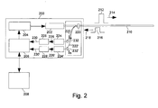
- Fig. 2 2 shows a schematic block diagram of a measuring device 200 for operating a glass fiber 210 designed as a temperature sensor.
- the measuring device 200 comprises as light source a laser 202 which generates and transmits light, in particular in the form of a light pulse 212, into the sensor fiber 210; a control unit 204 for driving the light source (laser) 202; a light extraction device 220 for coupling out (in the Fig.
- 2 light returned by the arrow 218) in particular in the form of a light pulse (measurement light pulse) 216 to be received from the sensor fiber 210 in measuring light guides 222, 222 '; the measuring light guides 220, 220 'for transmitting the decoupled received light, depending on the optical temperature measuring principle optionally required filter 232, 232'; Photodetectors 224, 224 'which convert the received light signals into electrical signals and output as detector output signals 226, 226'; Signal amplifiers 228, 228 'which amplify the detector output signals 226, 226' into amplifier output signals 230, 230 '; a sample and value detection unit 206 which receives the amplifier output signals 230, 230 'as input; and a computer 208 for driving and reading the sampling and value determination unit 206 is connected in bi-directional signal or data exchange with the unit 206.
- the measuring device 200 in particular the light source 202 and the light extraction device 220, are connected to the end of the glass fiber (sensor fiber) 210 led out of
- a measuring light guide 222, an optionally required optical filter 232, a photodetector 224, a signal amplifier 228 and an input with the associated input or evaluation electronics in the sampling and value determination unit 206 each form a light measuring channel.
- one or two light measuring channels are required and provided.
- a high power laser 202 In operation of the sensor fiber 210 as a Raman or Brillouin fiber sensor device, a high power laser 202 generates monochromatic light pulses 212 of high intensity I and a frequency f L. The light pulses 212 are coupled into the optical fiber 210, become therein (in the direction of in Fig.
- the coupled-in light 212 with the frequency f L interacts with molecules or molecular compounds in the temperature-sensitive subregion of the sensor glass fiber 210.
- the molecules or molecular compounds perform thermal oscillations with a natural frequency f R (the so-called Raman frequency) .
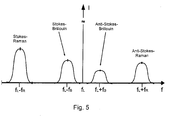
- the interaction of the coupled-in light with the frequency f L with the natural vibration frequency f R of the molecule or the molecular compound produces mixing frequencies f L + f R and f L -f R or corresponding frequency bands, which are called anti-Stokes-Raman or Stokes Raman light intensity distributions are called (see Fig. 5 ).
- respective light quanta of the frequency f L interact with the oscillatory molecule or molecule compound with the natural frequency f R.
- a light quantum of the frequency f L can according to the so-called Stokes-Raman scattering process the vibratory molecule or the molecular compound in a higher, ie to stimulate the natural frequency f R higher-frequency vibration state and thereby reduce its light frequency to the so-called Stokes Raman frequency f L -f R.
- a light quantum with the Stokes-Raman frequency f L -f R or a light pulse 216 runs in the in Fig.
- the photodetector 224 converts the received light pulse into an electrical detector output 216. This is amplified in a signal amplifier 228 and converted into a digital counter countable form (electric current or voltage pulse) and provided in a sample and value determination unit 206 Counter counted.
- an optical filter 232 is provided in front of the photodetector 224, which serves to pass the light generated by inelastic scattering processes in the corresponding frequency bands and to block light with other frequencies, in particular for blocking the high-intensity light with the laser excitation frequency f L.
- the so-called Anti-Stokes-Raman process Light with the frequency f L + f R generated.
- the molecule or the molecular compound is initially in a higher vibrational state, gives in the interaction with the light quantum of the frequency f L to the light quantum part of its vibrational energy, and is thereby in a lower vibration level one converted by the natural frequency f R lower frequency.
- the quantum of light absorbs the energy emitted, which increases its frequency from the value f L to the value f L + f R.
- the so-called anti-Stokes-Raman light with the frequency f L + f R is detected in a second measuring channel 220 ', 232', 224 ', 228'.
- the intensities of the light having the Stokes Raman frequency f L -f R (or the associated frequency distribution) and the light having the anti-Stokes Raman frequency f L + f R (FIG. or the associated frequency distribution) are evaluated the ratio of these two light intensities. From this intensity ratio, the temperature in the region of the optical fiber 210, where the inelastic scattering processes have taken place, is evaluated.
- the ratio of the intensities of the Stokes-Raman light and the anti-Stokes-Raman light depends on the temperature, because the number of at the beginning of the inelastic scattering process in the higher vibrational state molecules or molecular compounds in relation to the number of located in the lower vibrational state molecules or molecular compounds, ie the population probability of the higher vibrational state, depends on the temperature.
- the intrinsic vibration frequency f R of the molecule or molecular compound does not depend essentially on the temperature, but is a predetermined parameter which is characteristic of the type of molecule or molecular compound. Accordingly, the filter characteristics and the frequency responses of the optical filters 232 and 232 '(e.g., so-called monochromator devices) can be suitably set in advance for detection of Stokes light or anti-Stokes light.
- the probability of inelastic Raman scattering processes is on the order of 1:10 6 or less compared to the probability of elastic scattering processes.
- the light returning from the optical fiber 210 thus comprises a very high intensity component of elastically scattered light having the frequency f L and the Stokes or anti-Stokes light frequency bands, which are much weaker in relation to the scattering probability with respect to their intensity (see Fig. 5 ).
- the different intensity of the Stokes and anti-Stokes light distribution pair can be measured in the sampling and value determination unit 206 and the intensity ratio for temperature determination can be evaluated.
- the operation of the glass fiber (fiber sensor) 210 as a Brillouin fiber sensor device is based on another inelastic light scattering process, the so-called Brillouin scattering.
- Brillouin scattering the excitation light of the frequency f L generated and transmitted by the light source (the laser 202) interacts with the lattice vibrations of the material of the glass fiber, ie the glass in the temperature-sensitive region.
- lattice vibrations is meant herein the vibrations which a molecule or molecular group of the material (the glass) makes in relation to the surrounding molecules or groups of molecules.
- the lattice vibrations have characteristic natural frequencies f B which are smaller than the intramolecular vibrations (with frequencies f R ) occurring within a molecule or a molecular group which cause Raman scattering.
- the Brillouin frequency f B depends on the temperature.
- the change in the frequency of the excitation light from the value f L to the value f L + f B and the value f L -f B , ie, the grid vibration frequency corresponding frequency change f B evaluated and used for temperature determination.
- the Brillouin scattering is caused by the interaction of the excitation light with the frequency f L and the lattice vibrations with the natural frequency f B mixing frequencies f L + f B and f L -f B, respectively.
- a light quantum with the frequency f L -f B (Stokes-Brillouin light) is formed when the excitation light (frequency f L ) excites a lattice vibration or transfers it to a higher vibration level and thereby emits energy or its frequency around the Amount of the frequency of the excited lattice vibration reduced.
- a quantum of light with the frequency f L + f B (so-called anti-Stokes-Brillouin light) is formed when an active lattice vibration is transferred to a lower vibration state when interacting with the excitation light (frequency f L ) and thereby emits energy to an excitation light quantum , which thereby increases its frequency by the lattice vibration.
- Fig. 3 1 schematically shows a sensor fiber 310 embodied as a temperature sensor and a measuring device 300 for operating the same in optical, operative connection.
- the sensor fiber 310 comprises a light-conducting core region 311 extending over the entire longitudinal extension of the sensor fiber 310 and an optical surrounding surrounding this core region 311 insulating sheath (not marked).
- the sensor fiber 310 comprises a temperature-sensitive region 350, in which a luminescent crystal 340 is arranged in optical communication with the core region 311 as an actually temperature-sensitive element.
- the temperature-sensitive region 350 with the luminescent crystal 340 is in operation within a device operating according to the galvanic principle at a position particularly suitable for temperature measurement, for example within the limits of FIG Fig. 1 shown glass fiber structures 16, 26, 36 of the cathode, anode or Separator observed arranged.
- Another portion of the sensor fiber 310 is disposed outside of the galvanic-type device and connected to the measuring device 300.
- the measuring device 300 is an embodiment of a measuring device such as that modified in FIG. 1 for operating the sensor fiber 310 with the luminescent crystal 340 Fig. 2 shown.
- the measuring device 300 includes a light emitting diode (LED) 302 as a laser light source, a half mirror 320 as a light coupling device, an optical filter 332 for blocking light with the wavelength of the laser light source, and transmitting luminescent light 316 generated in the crystal 340, and a photodiode 324 as a photodetector, which receives a portion of the luminescent light 316 'to be detected and converts it to an electrical detector output signal 326 and S 2 , respectively.
- the detector output 326 is amplified, if necessary, by an electrical signal amplifier (not shown) and applied to a sample and sense unit (not shown). The latter evaluates the signal and determines the temperature corresponding to the signal.
- the light emitting diode 302 generates an intensity-modulated light signal S 1 (t) having a wavelength distribution comprising the wavelength ⁇ 1 suitable for exciting luminescent light in the crystal 340.
- the luminescence excitation light 312 emitted by the LED 302 is coupled into the photoconductive core region 311 of the sensor fiber 310, for example by a focusing device (not shown), passed from the sensor fiber 310 to the crystal 340 (as in FIG Fig. 3 indicated by arrows 312), and generates in the crystal 340 luminescent light having a wavelength ⁇ 2 specific to the crystal 340 or a wavelength distribution comprising the wavelength ⁇ 2, in particular as a maximum.
- the optical filter 332 passes through and reaches the photodetector 324, which converts the luminescent light 316 'into the electrical detector output signal 326.
- the wavelength ⁇ 2 of the luminescent light 316 depends on the temperature of the crystal 340.
- Al aluminum-doped gallium arsenide
- the optical filter 332 is tunable, wavelength-selective Filter element, for example, as a so-called optical monochromator formed.
- a temperature-dependent decay time of luminescence light pulses is known, for example, for the crystals zinc sulfide (ZnS) or chromium-doped yttrium aluminum garnet (Cr: YAG).
- ZnS crystals zinc sulfide
- Cr chromium-doped yttrium aluminum garnet
- the crystal 340 is excited with a light signal S 1 (t) having a time-modulated intensity.
- the light signal S 1 (t) may in particular have a rectangular change in intensity (rectangular function) or a stepped intensity change (step function) as a function of time.
- the crystal In response to the excitation by a light intensity modulated with such a jump function, the crystal (eg, ZnS, Cr: Yag) shows a luminescent light whose intensity changes in time according to an exponential function, for example.
- a sampling and evaluation unit (not shown) records the time dependence of the signal 326 and S 2 (t) produced by the luminescent light 316 in the photodetector 324 and determines therefrom by, for example, forming a derivative (time differentiated) Temperature of crystal 340.
- the sample and value determination unit determines a measure of the temperature of the crystal 340 to be a reciprocal of the time derivative, the so-called luminescence light intensity decay time. Evaluating 326 or S2.
- the sensor fiber 410 illustrated in schematic enlargement comprises a light-conducting core region 411 and an optically shielding sheath 413 surrounding the core region 411 and a partial region of the core region 411 formed as a temperature-sensitive region 450, in which a periodic refractive index modulation 426 is formed.
- the periodic refractive index modulation 426 formed in the fiber 410 is also referred to herein as the fiber Bragg grating.
- the fiber Bragg grating or the refractive index modulation 426 comprises a refractive index profile 428 formed in the core region 411 along the direction of propagation of the incident light 412 or L in, for example, sinusoidal (see the lower part of FIG Fig. 4 shown graph).
- a refractive index profile 428 formed in the core region 411 along the direction of propagation of the incident light 412 or L in, for example, sinusoidal (see the lower part of FIG Fig. 4 shown graph).
- a plurality of (in Example 5) periods of Refractive index modulus 426 for further simplification, in the lower part of the Fig.
- the refractive index modulation 426 acts as a wavelength-selective mirror (as shown in the lower left of FIG. 472 in graph 472) in reflection as a wavelength-selective intensity distribution P i of the injected light L in FIG Fig. 4 shown intensity distribution P r of the reflected light L r ) and in transmission as a wavelength-selective bandpass filter (as indicated by the in the graph 474 bottom right in FIG Fig. 4 shown intensity distribution P t of the transmitted light L t illustrated).
- the intensity distribution 474 in FIG Fig. 4 In the light 417 and L t transmitted by the refractive index modulation 426 (compare the intensity distribution 474 in FIG Fig. 4 ) are missing with respect to the irradiated light 412 and L in (compare the intensity distribution 470 in Fig. 4 ) the proportions of light 416 and I r reflected at the refractive index modulus 426 (compare the intensity distribution 472 in FIG Fig. 4 ). Accordingly, the intensity distribution 474 of the transmitted light shows a narrow-band dip with a minimum at the same wavelength ⁇ B , where the intensity distribution 472 of the reflected light has its maximum.
- the graph 472 (ie the intensity distribution of the light 416 reflected at the refractive index modulation 426 as a function of the light wavelength ⁇ ) shows a narrow-band intensity distribution with a clearly pronounced maximum at a specific wavelength ⁇ B.
- neff is the effective refractive index, ie the average refractive index of the refractive index profile n (I) shown in graph 428, the period length of the refractive index modulation 426 and ⁇ B the wavelength at the maximum of the narrowband intensity distribution of the reflected light (see graph 472) the wavelength at Minimum of the narrowband intensity distribution of the transmitted light (see graph 474), the so-called Bragg wavelength.
- the relationship between the Bragg wavelength ⁇ B of the reflected and transmitted light and the period length ⁇ of the refractive index modulation 426 described above by the equation can be clearly understood as the result of so-called constructive, ie mutually amplifying interference of partial waves of light which is reflected at different adjacent periods of the refractive index modulation 426.
- the graph 426 in Fig. 4 The explained condition for constructive interference in the reflection of partial waves is that the optical path 460 of a first partial wave reflected at one period of the refractive index modulation 426 differs from the optical path 426 of a second partial wave reflected at an adjacent period of the refractive index modulation 426 Wavelength ⁇ of the incident light (or a Ganzförmiges multiple thereof) is different.
- the optical path difference corresponds to twice the period length ⁇ of the refractive index modulation 426.
- the distance ⁇ of two adjacent periods of the refractive index modulation 426 also changes the wavelength ⁇ B of the maximum of the intensity spectrum 472 of the reflected light L r , 416 in the temperature measurement method with a fiber Bragg grating, the wavelength ⁇ B of the maximum (or minimum) of the intensity spectrum 472 (or 474) of the reflected (or transmitted) light determines and determines the temperature in the temperature-sensitive region 450 (with the Fiber Bragg grating).
- a fiber Bragg grating or periodic refractive index modulation 426 may be made, for example, by a photolithographic process as follows. First, a glass fiber 410 having a photosensitive core portion 411 is provided. To create therein a spatially periodic refractive index modulation 426 (ie, a fiber Bragg grating) in the glass fiber 410, a spatially modulated distribution of the short wavelength is used using a mask with a periodically modulated transparency for the short wavelength light, such as UV light Generated light and irradiated in the photosensitive, to be formed as a temperature-sensitive region 450 of the glass fiber 410.
- a spatially periodic refractive index modulation 426 ie, a fiber Bragg grating
- a spatially modulated distribution of the short wavelength is used using a mask with a periodically modulated transparency for the short wavelength light, such as UV light Generated light and irradiated in the photosensitive, to be formed as a temperature-sensitive region 450 of the glass fiber 410.
- photosensitive or “photosensitive” material is understood here to mean that the refractive index of the photosensitive material (as in the core region 411 to be formed as a fiber Bragg grating) for wavelengths in the optically measurable wavelength range is radiated by relatively short-wavelength light, for example UV Light, as a function of the dose of radiated, relatively short-wave light is changeable.
- relatively short-wavelength light for example UV Light
- the index of refraction changed in this way influences the propagation of light in the optical wavelength range, as is used as the temperature sensor as measuring light 412 during operation of the sensor fiber, and is not further changed by this light.
Landscapes
- Chemical & Material Sciences (AREA)
- Chemical Kinetics & Catalysis (AREA)
- Electrochemistry (AREA)
- General Chemical & Material Sciences (AREA)
- Engineering & Computer Science (AREA)
- Manufacturing & Machinery (AREA)
- Ceramic Engineering (AREA)
- Inorganic Chemistry (AREA)
- Materials Engineering (AREA)
- Measuring Temperature Or Quantity Of Heat (AREA)
- Investigating, Analyzing Materials By Fluorescence Or Luminescence (AREA)
- Secondary Cells (AREA)
- Cell Separators (AREA)
Applications Claiming Priority (1)
| Application Number | Priority Date | Filing Date | Title |
|---|---|---|---|
| DE102008057710A DE102008057710A1 (de) | 2008-11-17 | 2008-11-17 | Nach galvanischen Prinzipien arbeitende elektrische Einrichtung, wie ein Lithium-Ionen-Akkumulator, mit einem Temperatursensor |
Publications (2)
| Publication Number | Publication Date |
|---|---|
| EP2187472A2 true EP2187472A2 (fr) | 2010-05-19 |
| EP2187472A3 EP2187472A3 (fr) | 2010-09-15 |
Family
ID=42026047
Family Applications (1)
| Application Number | Title | Priority Date | Filing Date |
|---|---|---|---|
| EP09012721A Withdrawn EP2187472A3 (fr) | 2008-11-17 | 2009-10-07 | Dispositif électrique fonctionnant selon des principes galvaniques, comme un accumulateur au lithium-ion, et doté d'un capteur de température |
Country Status (3)
| Country | Link |
|---|---|
| US (1) | US8434940B2 (fr) |
| EP (1) | EP2187472A3 (fr) |
| DE (1) | DE102008057710A1 (fr) |
Cited By (6)
| Publication number | Priority date | Publication date | Assignee | Title |
|---|---|---|---|---|
| WO2012156091A1 (fr) * | 2011-05-17 | 2012-11-22 | Li-Tec Battery Gmbh | Procédé pour augmenter la capacité de charge d'un élément électrochimique doté d'un capteur, élément électrochimique doté d'un capteur et son procédé de production |
| EP2851972A1 (fr) * | 2013-09-20 | 2015-03-25 | Robert Bosch Gmbh | Batterie au lithium-ion à faible risque de soufflage |
| US10107867B2 (en) | 2013-11-12 | 2018-10-23 | Infineon Technologies Ag | Sensor arrangement, battery cell and energy system |
| CN111916858A (zh) * | 2019-05-10 | 2020-11-10 | 安德烈·斯蒂尔股份两合公司 | 电池组和处理系统 |
| EP4074537A1 (fr) * | 2021-04-16 | 2022-10-19 | Viavi Solutions Inc. | Membrane de détection à base de fibre optique |
| US12576748B2 (en) | 2021-04-16 | 2026-03-17 | Viavi Solutions Inc. | Data collection and analysis-based device monitoring |
Families Citing this family (20)
| Publication number | Priority date | Publication date | Assignee | Title |
|---|---|---|---|---|
| ITBG20070042A1 (it) * | 2007-07-31 | 2009-02-01 | Milano Politecnico | Sensore e metodo per determinare la temperatura lungo una fibra ottica. |
| DE102008057710A1 (de) * | 2008-11-17 | 2010-05-27 | Li-Tec Battery Gmbh | Nach galvanischen Prinzipien arbeitende elektrische Einrichtung, wie ein Lithium-Ionen-Akkumulator, mit einem Temperatursensor |
| DE102010046307B4 (de) | 2010-09-15 | 2018-04-12 | Fraunhofer-Gesellschaft zur Förderung der angewandten Forschung e.V. | Elektrochemische Zelle eines Akkumulators |
| CN102052976B (zh) * | 2010-11-04 | 2012-10-17 | 中国科学院嘉兴无线传感网工程中心 | 锂离子电池内部温度的测量装置和测量方法 |
| DE102011002841A1 (de) * | 2011-01-18 | 2012-07-19 | Fraunhofer-Gesellschaft zur Förderung der angewandten Forschung e.V. | Elektrochemischer Energiespeicher und Verfahren zur Bestimmung dessen Temperatur |
| US10439255B2 (en) | 2012-08-10 | 2019-10-08 | Battelle Memorial Institute | Optical monitoring of battery health |
| US10211489B2 (en) * | 2012-08-10 | 2019-02-19 | Battelle Memorial Institute | Integral light sources and detectors for an optical sensor to detect battery faults |
| US9570781B2 (en) | 2012-08-10 | 2017-02-14 | Battelle Memorial Institute | Optical waveguide methods for detecting internal faults in operating batteries |
| US9203122B2 (en) * | 2012-09-28 | 2015-12-01 | Palo Alto Research Center Incorporated | Monitoring and management for energy storage devices |
| DE102013106740A1 (de) * | 2013-06-27 | 2014-12-31 | Infineon Technologies Ag | Eine Vorrichtung zum Bestimmen eines Zustands eines Akkumulators oder einer Batterie, ein Akkumulator oder eine Batterie und ein Verfahren zum Bestimmen eines Zustands eines Akkumulators oder einer Batterie |
| US20150004450A1 (en) * | 2013-06-28 | 2015-01-01 | Naoki Matsumura | Detection Mechanism |
| FR3018962B1 (fr) * | 2014-03-18 | 2016-06-24 | Commissariat Energie Atomique | Dispositif autonome en energie dote de moyens d'autodestruction |
| US9583796B2 (en) | 2014-04-01 | 2017-02-28 | Palo Alto Research Center Incorporated | Method for monitoring/managing electrochemical energy device by detecting intercalation stage changes |
| US10403922B2 (en) * | 2014-07-23 | 2019-09-03 | Palo Alto Research Center Incorporated | Battery with embedded fiber optic cable |
| US10446886B2 (en) * | 2014-07-23 | 2019-10-15 | Palo Alto Research Center Incorporated | Embedded fiber optic cables for battery management |
| US10177421B2 (en) | 2015-02-12 | 2019-01-08 | Battelle Memorial Institute | Battery cell structure with limited cell penetrations |
| US10574365B2 (en) * | 2016-10-14 | 2020-02-25 | Tiveni Mergeco, Inc. | Optical communications interface for battery modules of an energy storage system |
| US20180321325A1 (en) | 2017-05-08 | 2018-11-08 | Aleksandra Fortier | Embedded Sensors for In-Situ Cell Monitoring of Batteries |
| DE102021129640A1 (de) | 2021-11-15 | 2023-05-17 | Bayerische Motoren Werke Aktiengesellschaft | Batteriezelle und Batterie mit einer solchen Batteriezelle |
| CN116826219A (zh) * | 2023-08-28 | 2023-09-29 | 宁德时代新能源科技股份有限公司 | 电池、用电装置和电池的装配方法 |
Family Cites Families (16)
| Publication number | Priority date | Publication date | Assignee | Title |
|---|---|---|---|---|
| US5090818A (en) * | 1982-08-06 | 1992-02-25 | Kleinerman Marcos Y | Fiber optic systems for sensing temperature and other physical variables |
| JPH05166545A (ja) * | 1991-12-11 | 1993-07-02 | Japan Storage Battery Co Ltd | 密閉鉛蓄電池 |
| US5623196A (en) * | 1994-12-27 | 1997-04-22 | Motorola, Inc. | Apparatus and method of simulating high battery temperature in a rechargeable battery |
| US7813226B2 (en) * | 2002-12-13 | 2010-10-12 | Vision Works Ip Corporation | Timing system and device and method for making the same |
| DE10238941B4 (de) * | 2002-08-24 | 2013-03-28 | Evonik Degussa Gmbh | Elektrischer Separator, Verfahren zu dessen Herstellung und Verwendung in Lithium-Hochleistungsbatterien sowie eine den Separator aufweisende Batterie |
| US7811707B2 (en) * | 2004-12-28 | 2010-10-12 | Boston-Power, Inc. | Lithium-ion secondary battery |
| DE102006049746A1 (de) * | 2006-10-21 | 2008-04-24 | Dilo Trading Ag | Separator für Lithium-Polymer Batterien und Verfahren zur Herstellung derselben |
| US8350529B2 (en) * | 2006-11-10 | 2013-01-08 | Lithium Balance A/S | Battery management system |
| KR100812742B1 (ko) * | 2007-04-03 | 2008-03-12 | 주식회사 에이티티알앤디 | 2차 전지 |
| DE102008052986A1 (de) * | 2008-10-23 | 2010-04-29 | Li-Tec Battery Gmbh | Batteriemanagementsystem für eine nach galvanischen Prinzipien arbeitende elektrische Einrichtung, beispielsweise eine Lithium-Ionen-Zelle |
| DE102008046510A1 (de) * | 2008-09-10 | 2010-03-11 | Li-Tec Battery Gmbh | Nach galvanischen Prinzipien arbeitende elektrische Einrichtungen, wie beispielsweise Lithium-Ionen-Zelle, mit einer Betriebszustandssteuerung |
| JP5166545B2 (ja) | 2008-10-08 | 2013-03-21 | 株式会社日立ハイテクノロジーズ | ステージ駆動装置 |
| DE102008053009A1 (de) * | 2008-10-23 | 2010-04-29 | Li-Tec Battery Gmbh | Elektroden für eine nach galvanischen Prinzipien arbeitende elektrische Einrichtung, wie Lithium-Ionen-Zellen, und Verfahren zu deren Herstellung |
| DE102008053089A1 (de) * | 2008-10-24 | 2010-04-29 | Li-Tec Battery Gmbh | Akkumulator mit mehreren galvanischen Zellen |
| DE102008057710A1 (de) * | 2008-11-17 | 2010-05-27 | Li-Tec Battery Gmbh | Nach galvanischen Prinzipien arbeitende elektrische Einrichtung, wie ein Lithium-Ionen-Akkumulator, mit einem Temperatursensor |
| WO2012054473A1 (fr) * | 2010-10-18 | 2012-04-26 | Johns Hopkins University | Phasemètre de batterie servant à déterminer les températures internes de cellules au lithium-ion rechargeables sous charge et sous décharge |
-
2008
- 2008-11-17 DE DE102008057710A patent/DE102008057710A1/de not_active Withdrawn
-
2009
- 2009-10-07 EP EP09012721A patent/EP2187472A3/fr not_active Withdrawn
- 2009-11-16 US US12/619,084 patent/US8434940B2/en not_active Expired - Fee Related
Cited By (14)
| Publication number | Priority date | Publication date | Assignee | Title |
|---|---|---|---|---|
| WO2012156091A1 (fr) * | 2011-05-17 | 2012-11-22 | Li-Tec Battery Gmbh | Procédé pour augmenter la capacité de charge d'un élément électrochimique doté d'un capteur, élément électrochimique doté d'un capteur et son procédé de production |
| EP2851972A1 (fr) * | 2013-09-20 | 2015-03-25 | Robert Bosch Gmbh | Batterie au lithium-ion à faible risque de soufflage |
| US10107867B2 (en) | 2013-11-12 | 2018-10-23 | Infineon Technologies Ag | Sensor arrangement, battery cell and energy system |
| CN111916858A (zh) * | 2019-05-10 | 2020-11-10 | 安德烈·斯蒂尔股份两合公司 | 电池组和处理系统 |
| EP3736872A1 (fr) * | 2019-05-10 | 2020-11-11 | Andreas Stihl AG & Co. KG | Bloc d'accumulateur et système d'usinage |
| US12062769B2 (en) | 2019-05-10 | 2024-08-13 | Andreas Stihl Ag & Co. Kg | Battery pack and treatment system |
| EP4074536A3 (fr) * | 2021-04-16 | 2022-12-21 | Viavi Solutions Inc. | Disposition de membrane de détection à base de fibre optique |
| US12031859B2 (en) | 2021-04-16 | 2024-07-09 | Viavi Solutions Inc. | Optical fiber-based sensing membrane |
| EP4074537A1 (fr) * | 2021-04-16 | 2022-10-19 | Viavi Solutions Inc. | Membrane de détection à base de fibre optique |
| US12092515B2 (en) | 2021-04-16 | 2024-09-17 | Viavi Solutions Inc. | Optical fiber-based sensing membrane layout |
| US12281934B2 (en) | 2021-04-16 | 2025-04-22 | Viavi Solutions Inc. | Optical fiber-based sensing membrane layout |
| EP4571934A3 (fr) * | 2021-04-16 | 2025-09-10 | Viavi Solutions Inc. | Membrane de détection à base de fibre optique |
| US12474202B2 (en) | 2021-04-16 | 2025-11-18 | Viavi Solutions Inc. | Optical fiber-based sensing membrane |
| US12576748B2 (en) | 2021-04-16 | 2026-03-17 | Viavi Solutions Inc. | Data collection and analysis-based device monitoring |
Also Published As
| Publication number | Publication date |
|---|---|
| EP2187472A3 (fr) | 2010-09-15 |
| US8434940B2 (en) | 2013-05-07 |
| DE102008057710A1 (de) | 2010-05-27 |
| US20100124250A1 (en) | 2010-05-20 |
Similar Documents
| Publication | Publication Date | Title |
|---|---|---|
| EP2187472A2 (fr) | Dispositif électrique fonctionnant selon des principes galvaniques, comme un accumulateur au lithium-ion, et doté d'un capteur de température | |
| EP2666227B1 (fr) | Accumulateur d'énergie électrochimique et procédé permettant d'en déterminer la température | |
| US10439255B2 (en) | Optical monitoring of battery health | |
| DE102013106740A1 (de) | Eine Vorrichtung zum Bestimmen eines Zustands eines Akkumulators oder einer Batterie, ein Akkumulator oder eine Batterie und ein Verfahren zum Bestimmen eines Zustands eines Akkumulators oder einer Batterie | |
| DE102008026190A1 (de) | Vorrichtung zum Erzeugen oder Empfangen von Terahertz-Strahlung | |
| DE3500247A1 (de) | Vorrichtung zum eliminieren der hintergrundstoerung bei fluoreszenzmessungen | |
| DE102005019386B4 (de) | Gerät zum Polymerisieren von polymerisierbarem Dentalmaterial sowie Verfahren zur Bestimmung des Polymerisationsgrades | |
| WO2016169702A1 (fr) | Système de batterie et procédé de surveillance d'une température d'un système de batterie | |
| DE112021006826T5 (de) | Messgerät für eine biologische komponente und verfahren zur messung einer biologischen komponenten | |
| DE102009034854A1 (de) | Anordnung und Verfahren zum Bestimmen eines Ladezustands | |
| WO2014026839A2 (fr) | Capteur à fibre optique et procédé de mesure | |
| DE102012203655A1 (de) | Energiespeicher mit Indikator zum Erkennen temperaturbedingter Degradation oder sicherheitskritischen Zustands sowie entsprechendes Verfahren | |
| DE102015101608B4 (de) | Verfahren zur Signalweiterleitung, Vorrichtung mit einer optischen Faser und Detektionssystem | |
| WO2012084232A1 (fr) | Dispositif, équipement de production et procédé pour la caractérisation de surfaces limites de matériaux par irradiation thz, et utilisation de ce dispositif | |
| US20250189384A1 (en) | Sensor for sensing temperature and measuring the state of charge (SOC) of a fiber-optic accumulator comprising one or more thermoluminescent materials, at one or more emission peaks in a region of variation of the optical absorption spectrum of the insertion material of an electrode | |
| WO2021032418A1 (fr) | Procédés et agencements pour identifier l'état de charge de batteries au lithium-ion à l'aide de moyens optiques | |
| DE102012223089B4 (de) | Verfahren und Vorrichtung zur Messung elektrischer Spannung | |
| DE19636229B4 (de) | Verfahren und Vorrichtung zur Bestimmung von Degradationsprozessen in Halbleiterlasern | |
| DE102005045538B3 (de) | Vorrichtung und Verfahren zur Bestimmung des Brechungsindex eines Fluids | |
| DE102018001502A1 (de) | Verfahren zur Ausbildung einer dünnen Solid Elektrolyte Interface während der Formierung einer wiederaufladbaren, elektrochemischen Energiespeicherzelle | |
| DE102011085394A1 (de) | Verfahren und Vorrichtung zur Analyse eines Fluids mittels Evaneszenzfeldspektroskopie und Dielektrophorese | |
| DE10049951A1 (de) | Faseroptischer Sensor zur Bestimmung eines Analyten mit hoch doppelbrechendem Lichtwellenleiter sowie Verwendung des faseroptischen Sensors | |
| DE102017202358A1 (de) | Verfahren und vorrichtung zum betrieb eines elektrochemischen energiespeichers | |
| DE102011083167A1 (de) | Energiespeichersystem und Zustandserkennungssystem umfassend das Energiespeichersystem | |
| DE102013004504B4 (de) | Vorrichtung zur Bewertung der Kristallinität eines Halbleiters und Verfahren zur Bewertung der Kristallinität eines Halbleiters |
Legal Events
| Date | Code | Title | Description |
|---|---|---|---|
| PUAI | Public reference made under article 153(3) epc to a published international application that has entered the european phase |
Free format text: ORIGINAL CODE: 0009012 |
|
| AK | Designated contracting states |
Kind code of ref document: A2 Designated state(s): AT BE BG CH CY CZ DE DK EE ES FI FR GB GR HR HU IE IS IT LI LT LU LV MC MK MT NL NO PL PT RO SE SI SK SM TR |
|
| AX | Request for extension of the european patent |
Extension state: AL BA RS |
|
| PUAL | Search report despatched |
Free format text: ORIGINAL CODE: 0009013 |
|
| AK | Designated contracting states |
Kind code of ref document: A3 Designated state(s): AT BE BG CH CY CZ DE DK EE ES FI FR GB GR HR HU IE IS IT LI LT LU LV MC MK MT NL NO PL PT RO SE SI SK SM TR |
|
| AX | Request for extension of the european patent |
Extension state: AL BA RS |
|
| RIC1 | Information provided on ipc code assigned before grant |
Ipc: H01M 4/66 20060101ALI20100812BHEP Ipc: H01M 2/16 20060101ALI20100812BHEP Ipc: H01M 10/058 20100101ALI20100812BHEP Ipc: H01M 10/48 20060101ALI20100812BHEP Ipc: H01M 10/052 20100101AFI20100324BHEP |
|
| 17P | Request for examination filed |
Effective date: 20101116 |
|
| RIN1 | Information on inventor provided before grant (corrected) |
Inventor name: LACHENMEIER, WALTER, DR.-ING. Inventor name: GUTSCH, ANDREAS, DR. Inventor name: SCHAEFER, TIM |
|
| STAA | Information on the status of an ep patent application or granted ep patent |
Free format text: STATUS: THE APPLICATION IS DEEMED TO BE WITHDRAWN |
|
| 18D | Application deemed to be withdrawn |
Effective date: 20150501 |