EP2187495A2 - Resonanzmitigationssystem und Verfahren - Google Patents
Resonanzmitigationssystem und Verfahren Download PDFInfo
- Publication number
- EP2187495A2 EP2187495A2 EP09175572A EP09175572A EP2187495A2 EP 2187495 A2 EP2187495 A2 EP 2187495A2 EP 09175572 A EP09175572 A EP 09175572A EP 09175572 A EP09175572 A EP 09175572A EP 2187495 A2 EP2187495 A2 EP 2187495A2
- Authority
- EP
- European Patent Office
- Prior art keywords
- voltage
- coupled
- power system
- resonance
- high voltage
- Prior art date
- Legal status (The legal status is an assumption and is not a legal conclusion. Google has not performed a legal analysis and makes no representation as to the accuracy of the status listed.)
- Withdrawn
Links
Images


Classifications
-
- H—ELECTRICITY
- H02—GENERATION; CONVERSION OR DISTRIBUTION OF ELECTRIC POWER
- H02H—EMERGENCY PROTECTIVE CIRCUIT ARRANGEMENTS
- H02H7/00—Emergency protective circuit arrangements specially adapted for specific types of electric machines or apparatus or for sectionalised protection of cable or line systems, and effecting automatic switching in the event of an undesired change from normal working conditions
- H02H7/26—Sectionalised protection of cable or line systems, e.g. for disconnecting a section on which a short-circuit, earth fault, or arc discharge has occured
-
- H—ELECTRICITY
- H02—GENERATION; CONVERSION OR DISTRIBUTION OF ELECTRIC POWER
- H02J—ELECTRIC POWER NETWORKS; CIRCUIT ARRANGEMENTS OR SYSTEMS FOR SUPPLYING OR DISTRIBUTING ELECTRIC POWER; SYSTEMS FOR STORING ELECTRIC ENERGY
- H02J3/00—Circuit arrangements for AC mains or AC distribution networks
- H02J3/18—Arrangements for adjusting, eliminating or compensating reactive power in networks
-
- H—ELECTRICITY
- H02—GENERATION; CONVERSION OR DISTRIBUTION OF ELECTRIC POWER
- H02J—ELECTRIC POWER NETWORKS; CIRCUIT ARRANGEMENTS OR SYSTEMS FOR SUPPLYING OR DISTRIBUTING ELECTRIC POWER; SYSTEMS FOR STORING ELECTRIC ENERGY
- H02J3/00—Circuit arrangements for AC mains or AC distribution networks
- H02J3/001—Arrangements for handling faults or abnormalities, e.g. emergencies or contingencies
- H02J3/00125—Transmission line or load transient problems, e.g. overvoltage, resonance or self-excitation of inductive loads
-
- H—ELECTRICITY
- H02—GENERATION; CONVERSION OR DISTRIBUTION OF ELECTRIC POWER
- H02J—ELECTRIC POWER NETWORKS; CIRCUIT ARRANGEMENTS OR SYSTEMS FOR SUPPLYING OR DISTRIBUTING ELECTRIC POWER; SYSTEMS FOR STORING ELECTRIC ENERGY
- H02J3/00—Circuit arrangements for AC mains or AC distribution networks
- H02J3/01—Arrangements for reducing harmonics or ripples
-
- H—ELECTRICITY
- H02—GENERATION; CONVERSION OR DISTRIBUTION OF ELECTRIC POWER
- H02H—EMERGENCY PROTECTIVE CIRCUIT ARRANGEMENTS
- H02H7/00—Emergency protective circuit arrangements specially adapted for specific types of electric machines or apparatus or for sectionalised protection of cable or line systems, and effecting automatic switching in the event of an undesired change from normal working conditions
- H02H7/22—Emergency protective circuit arrangements specially adapted for specific types of electric machines or apparatus or for sectionalised protection of cable or line systems, and effecting automatic switching in the event of an undesired change from normal working conditions for distribution gear, e.g. bus-bar systems; for switching devices
- H02H7/228—Emergency protective circuit arrangements specially adapted for specific types of electric machines or apparatus or for sectionalised protection of cable or line systems, and effecting automatic switching in the event of an undesired change from normal working conditions for distribution gear, e.g. bus-bar systems; for switching devices for covered wires or cables
-
- H—ELECTRICITY
- H02—GENERATION; CONVERSION OR DISTRIBUTION OF ELECTRIC POWER
- H02H—EMERGENCY PROTECTIVE CIRCUIT ARRANGEMENTS
- H02H9/00—Emergency protective circuit arrangements for limiting excess current or voltage without disconnection
- H02H9/005—Emergency protective circuit arrangements for limiting excess current or voltage without disconnection avoiding undesired transient conditions
-
- Y—GENERAL TAGGING OF NEW TECHNOLOGICAL DEVELOPMENTS; GENERAL TAGGING OF CROSS-SECTIONAL TECHNOLOGIES SPANNING OVER SEVERAL SECTIONS OF THE IPC; TECHNICAL SUBJECTS COVERED BY FORMER USPC CROSS-REFERENCE ART COLLECTIONS [XRACs] AND DIGESTS
- Y02—TECHNOLOGIES OR APPLICATIONS FOR MITIGATION OR ADAPTATION AGAINST CLIMATE CHANGE
- Y02E—REDUCTION OF GREENHOUSE GAS [GHG] EMISSIONS, RELATED TO ENERGY GENERATION, TRANSMISSION OR DISTRIBUTION
- Y02E40/00—Technologies for an efficient electrical power generation, transmission or distribution
- Y02E40/30—Reactive power compensation
Definitions
- the invention relates generally to resonance in high voltage power systems and in particular, to a system and method for mitigating resonance from harmonic distortion.
- Converting alternate current (AC) power to direct current (DC) power and vice versa may include circuits such as rectifier networks with passive input and output filters that produce significant harmonic distortion of the AC current waveforms. Harmonic distortion typically causes undesirable power dissipation and creates unwanted electromagnetic interference that couples into other lines and equipment. Distorted AC current waveforms may also excite undesirable vibration in transformers, rotating machinery where electromagnetic couplings are implemented. In addition, input power factor is often adversely affected resulting in decreased operating efficiency.
- AC to DC power conversion approaches may involve active circuits utilizing various pulse width modulated (PWM) switching mode techniques.
- PWM techniques produce discrete circuit current pulses at the modulation frequency that require substantial filtering to limit harmonic distortion and electromagnetic interference.
- One such substantial filtering includes active filtering.
- Cancellation techniques are applied to PWM converter control systems in order to minimize harmonic distortion. However, such techniques are less effective for higher frequencies.
- active filters employ a power system line level reference (sensed current or voltage at the load or source of the power system) for closed-loop control.
- a disadvantage of sensing current or voltage at the load or source of a power system includes devices for sensing that are exposed to the full-line voltage or current of the power system, whereby expensive, high power rated sensing devices are required.
- the system includes a voltage damper coupled to the high voltage power system between a cable sheath and an earth connection.
- the voltage damper is configured to clamp voltage peaks.
- the system also includes a frequency shifter coupled across the voltage damper and configured to displace a resonance frequency of the high voltage power system.
- a device for mitigating resonance includes a tunable voltage regulator configured to clamp resonant voltage peaks.
- the device also includes a frequency tuner coupled to the tunable voltage regulator and configured to shift a system frequency away from a resonance frequency.
- a harmonic resonance mitigating device in one embodiment, includes a variable resistor configured to restrain voltage peaks resulting from a harmonic distortion.
- the device also includes a variable inductor coupled to the variable resistor and configured to shift a system resonance frequency.
- the device further includes a varistor coupled to the variable inductor and configured to arrest abnormal voltage spikes.
- a system for monitoring and mitigating resonance from harmonic distortion in a high voltage power system includes a voltage damper coupled to the high voltage power system between non-voltage carrying portion of a cable and an earth connection, the voltage damper configured to clamp voltage peaks.
- the system includes a frequency shifter coupled across the voltage damper and configured to displace a resonance frequency of the high voltage power system.
- the system further includes a varistor coupled across the voltage damper and configured to clamp abnormal voltage spikes.
- the system further includes a monitoring device coupled to the voltage damper and configured to record a plurality of network parameters.
- An auto tunable circuit is coupled to the monitoring device and configured to tune the voltage arrested and the frequency shifter based upon the network parameters.
- a method for mitigating resonance from harmonic distortion in a high voltage power system includes introducing a complex impedance in an earth connection by clamping voltage peaks originating from resonance in harmonic distortion. The method also includes shifting a resonance frequency of the high voltage power system and arresting an abnormal voltage raise in the high voltage power system.
- a method for reducing resonance in an industrial electrical system includes dampening a resonant voltage peak from harmonic distortion, changing a system resonance frequency by introducing a tunable earth connector, and altering a harmonic profile of the industrial electrical system by introducing a complex impedance in an earth circuit.
- a system for reducing resonance in harmonic distortion includes a power system having a plurality of components interconnected via cables and configured to perform a pre-determined functions.
- the system further includes a tunable earth connector coupled to at least one respective non-voltage carrying portion of the cable and an earth connection in the power system.
- the tunable earth connector includes at least one variable resistor, at least one tunable inductor or tunable capacitor coupled across the variable resistor.
- the tunable earth connector is configured to reduce a resonance in harmonic distortion in the power system.
- a system for reducing resonance from harmonic distortion in a high voltage power system includes a voltage damper coupled to the high voltage power system between non-voltage carrying portion of a cable and an earth connection.
- the voltage damper is configured to clamp voltage peaks.
- the system further includes a frequency shifter coupled across the voltage damper and configured to displace a resonance frequency of the high voltage power system.
- a system for reducing resonance from harmonic distortion in a high voltage power system includes a resistor coupled to the high voltage power system between non-voltage carrying portion of a cable and an earth connection, the resistor configured to clamp voltage peaks.
- a system for reducing resonance from harmonic distortion in a high voltage power system includes an inductor coupled to the high voltage power system between a non-voltage carrying portion of a cable and an earth connection, the inductor configured to shift resonant peaks.
- FIG. 1 illustrates a block diagram of a power system wherein an earth connector is implemented according to an aspect of the present technique
- FIG. 2 is a block diagram indicating various components of the earth connector as implemented in FIG. 1 ;
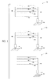
- FIG. 3 is a block diagram illustrating various configurations of earth connection of FIG. 1 ;
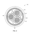
- FIG. 4 illustrates a cross sectional view of high voltage cable
- FIG. 5 is a graph illustrating voltage spectrum of the power system in FIG. 1 .
- three-phase alternating current (AC) power employs three conductors of electrical power each providing a pure sine wave of current and voltage, the sine waves having equal and constant amplitude and frequency, and each phase separated from the others by 120 degrees of phase angle.
- harmonics cause loss of energy in motors and may effect the efficiency and stability of power supplies in sensitive electronic equipment. Harmonics may also cause resonance resulting in unwanted voltage spikes. For these reasons limitations on harmonic levels in AC power have been established in many countries.
- the harmonic distortion in an AC power main may be reduced by the use of passive filters incorporating inductors and capacitors that have a series resonance or parallel resonance at the harmonic frequencies. Filters may also be configured to address resonance arising due to harmonics, by acting as damping circuits that modify resonance frequency or via a damping circuit that clamps resonant peaks. These passive filters are placed across the power mains to shunt the damaging harmonics. Such passive filters have a simple structure but a number of disadvantages. Passive filters are typically bulky and expensive; do not adapt to changes in harmonic frequencies caused by shifts in the fundamental AC frequency; and do not account for variations in the series impedance of the power mains.
- active filters in which a power amplifier (such as a pulse width modulated (PWM) power supply) is connected directly to the power main to provide a countervailing harmonic current for canceling the distortion.
- PWM pulse width modulated
- Such active filters may be used with passive filters in a hybrid arrangement in which the PWM power supply is connected to the power mains through a series resonant circuit to block the AC fundamental and hence to decrease loading on the PWM power supply.
- active filters and hybrid filters have disadvantages such as requiring a unique design for a given system, and becoming less effective with a change in power system parameters.
- power losses occur with active filtering as active filters are always coupled to the power system whether filtering occurs or otherwise.
- the power system 10 includes a receiving station 14 that receives power from high voltage grid 12, typically transmitted via long distance transmission lines (not shown).
- the power received in the form of high voltages via transmission lines are stepped down to lower voltages by a power transformer 18 coupled to the receiving station and a switching station 22 via high voltage cables 16 and 20.
- the switching station 22 further enables distribution of power via transformers 24.
- Circuit breakers 26 are coupled to the transformers 24 to control a flow of power downstream.
- Utilities such as motor 28 are coupled to the transformers 24 via circuit breakers.
- Motor 28 is illustrated herein for example. However, any utility that requires power may be coupled in the power system.
- An earth connector 32 is coupled between the high voltage cable sheath (via 30) and a ground 36 also referred to as earth connection. The working details and components of earth connector 32 are described in detail below.
- the earth connector 32 may include a tunable resistor 42, a varistor 44, and a tunable inductor 46 coupled in parallel.
- tunable referenced herein is used synonymously with the term "variable.”
- tunable or variable elements in the embodiments may be fixed to a particular value after appropriate system design.
- tunable elements in the embodiments described herein may be replaced by fixed elements such as a resistor, an inductor, or a capacitor.
- the earth connector 32 includes connection 48 that may be coupled to a point in an earth circuit and connection 50 coupled to ground 36 as referenced in FIG. 1 of the power system.
- tunable earth connector 32 may include parallel connection of the tunable/variable resistor 42 (designated as a damper configured to dampen resonance peaks), the tunable inductor 46 (designated as a frequency shifter configured to shift a resonance frequency), and the varistor 44 (designated as a voltage arrester/surge arrester to limit any abnormal voltage spikes across the earth connector).
- the resistor 42 may be configured as a tunable voltage regulator configured to provide multiple resistance points to dampen voltage peaks arising from resonance.
- the tunable inductor 46 may be configured to de-tune and/or shift a parallel resonance frequency.
- a variable capacitor (frequency tuner) may be coupled to the earth connector 32 configured to change a harmonic resonance frequency.
- the varistor 44 or surge arrester may include, for example, a metal oxide varistor.
- the earth connector may include a resistor coupled between non-voltage carrying portion of a cable such as cable sheath or cable screen, and an earth or ground.
- the resistor is configured to clamp voltage peaks originating from the harmonics.
- a variable resistor to tune the resistance as required by the high voltage system design may replace the resistor.
- the earth connector may include an inductor coupled between non-voltage carrying portion of a cable such as cable sheath or cable screen, and an earth or ground.
- the inductor is configured to shift the resonant peaks originating from the harmonics.
- a variable inductor to tune the inductance as required by the high voltage system design may replace the inductor. Such variable inductor may also shift resonance frequency of the high voltage system.
- a system for monitoring and mitigating resonance from harmonic distortion in a high voltage power system may be implemented along with the tunable earth connector as described in FIG. 2 .
- the monitoring and mitigating system may include a variable resistor 42 (voltage arrestor) configured to clamp voltage peaks that may occur as a result of resonance from harmonic distortion.
- a tunable inductor and/or variable capacitor 46 may be coupled across the variable resistor 42 and configured to displace a resonance frequency of the high voltage power system 10 as referenced in FIG. 1 .
- a protection device such as varistor 44 may be coupled across the variable resistor 42 and configured to clamp abnormal voltage spikes.
- a monitoring device (not shown) may be implemented that is coupled to the variable resistor and configured to record network parameters.
- Network parameters may include, for example, an inductor current flowing through the tunable inductor.
- An auto tunable circuit may be coupled to the monitoring device and configured to tune the variable resistor and the tunable inductor based upon the inductor current. For example, as the inductance is varied, there may exist a certain value wherein the current flowing in the inductor may be minimum, indicating that the effect of tuning causes shifting away from resonance frequency.
- FIG. 3 illustrates various configurations of an earth connection that may be implemented to couple the earth connector between the high voltage cable sheath and earth/ground.
- a double point bonding configuration may be implemented as illustrated by reference numeral 52.
- Three-phase high voltage cable comprises a plurality of cores 54, 56, and 58 that are surrounded by cable sheath/screens 60, 62, and 64, respectively.
- the screens at 66 and 68 are coupled together via an earth conductor 70.
- the earth conductor 70 is further coupled to the ground 36 via the earth connector 32.
- the earth connector 32 may be coupled between earth conductor 70 and screen 66 to cancel the common mode harmonics.
- earth connection configuration such as double point bonding without earth conductor may be implemented as illustrated by reference numeral 72.
- the cable screens 60, 62, and 64 are coupled at 66 and 68 and connected to ground 36 separately via earth connectors 32 and 74.
- a single point bonding as illustrated by reference numeral 76 may be implemented to connect the earth connector in the power system.
- the cable screens 60, 62, and 64 are coupled to the ground 36 via earth connector 32.
- three earth connectors may be coupled individually between each phase screen and the ground, for example between 60 and 36. While only three exemplary configurations are depicted in FIG. 3 , many such configurations are contemplated within the instant invention. Power systems having different configurations may implement one or more of such earth connection configurations to mitigate harmonic resonance.
- FIG. 4 illustrates a cross sectional view of high voltage cable 20 as referenced in power system of FIG. 1 .
- Components of the high voltage cable as indicated by the reference numeral 82 include copper conductors 84, 86, 88 that are stranded and compacted often referred to as a core.
- a conductor screen 90 typically made of an extruded semi-conductive compound surrounds each core.
- An insulating layer 92 surrounds the conductor screen.
- a semi-conductive insulation screen 94 is disposed around the insulating layer 92. Similar arrangement of conductor screen 90, insulating layer 92, and semi-conductive insulation screen 94 are disposed around core 86 and 88.
- the three cores 84, 86, and 88 along with the conductor screen 90, insulating layer 92, insulation shield 94 and earth conductors 96 are bound together by binder tape 99.
- the space between the binder tape 99 and the core may include fillers 98 such as polypropylene strings.
- An armour 100 typically made of galvanized round steel wires is disposed around the fillers 98.
- Serving tapes 102 along with bituminous compound and/or polypropylene strings are provided as outermost protection for the cable.
- the earth connector may be coupled to the earth conductors 96 and armour/sheath 100 and the ground 36 as referenced in FIG. 1 . It may be noted that the earth connector is connected to a non-voltage carrying portion of the high voltage cable 20. While the armour/sheath is discussed, other such non-voltage carrying portions are contemplated by this invention.
- FIG. 5 is a graph illustrating voltage spectrum of a representative high voltage power system.
- Graph 110 represents a voltage spectrum in a 33kV grid with voltage amplitude on y-axis 112 and frequency (0 - 10 kHz) on x-axis 114. It may be noted that there are several voltage spikes 116 indicating resonance in the frequency range of about 2kHz to about 3 kHz.
- Graph 120 represents voltage spectrum in the 33kV grid with tunable earth connector 32 as implemented in FIG. 1 discussed above. The graph 120 indicates voltage amplitude on y-axis 122 and frequency (0 - 10 kHz) on x-axis 124. In may be noted that the voltage amplitude scale on the graph 120 is smaller compared to the voltage amplitude scale on graph 110.
- voltage spikes 126 are substantially lower (at least about six times lower in amplitude) in a frequency range of about 2kHz to about 3 kHz indicating tunable earth connector helps mitigate resonance.
- tunable earth connector may be implemented as a retrofit solution against an electrical resonance by tuning the resonant point (vary tunable inductor) to a location where no resonance occurs.
- tuning may be implemented manually or by a simple control system that measures the inductor current and correspondingly changes the inductor value until the measured current reaches a minimum.
- a parallel resistor may be implemented in the earth connector 32 as referenced in FIG. 1 to introduce damping. It may be appreciated by one skilled in the art, that the illustrated voltage spectrum in FIG. 5 are part of exemplary embodiments. However, any power system that exhibits electrical resonance may implement the earth connector as a mitigating solution.
- embodiments of the invention are cleverly articulated such that power losses are minimized in the mitigation system and tunable components implemented to add flexibility to incorporate change in power system parameters.
- such earth connector design can be applied to a wide range of applications, including applications where variable speed motors are connected. Such variable speed motors having variable electrical frequency, where several resonance points up to the lower frequency range may be mitigated.
- the tunable earth connector is best suited as a countermeasure against electrical resonance as cancellation techniques applied in the converter control system become less effective at higher frequency.
- the tunable earth connector provides a low voltage (low cost) device that can be used as a retrofit solution against electrical resonance caused in large drive applications (e. g.
Landscapes
- Engineering & Computer Science (AREA)
- Power Engineering (AREA)
- Emergency Protection Circuit Devices (AREA)
- Supply And Distribution Of Alternating Current (AREA)
- Power Conversion In General (AREA)
Applications Claiming Priority (1)
| Application Number | Priority Date | Filing Date | Title |
|---|---|---|---|
| US12/270,885 US20100123356A1 (en) | 2008-11-14 | 2008-11-14 | Resonance mitigation system and method |
Publications (2)
| Publication Number | Publication Date |
|---|---|
| EP2187495A2 true EP2187495A2 (de) | 2010-05-19 |
| EP2187495A3 EP2187495A3 (de) | 2014-08-20 |
Family
ID=41527771
Family Applications (1)
| Application Number | Title | Priority Date | Filing Date |
|---|---|---|---|
| EP09175572.8A Withdrawn EP2187495A3 (de) | 2008-11-14 | 2009-11-10 | Resonanzmitigationssystem und Verfahren |
Country Status (7)
| Country | Link |
|---|---|
| US (1) | US20100123356A1 (de) |
| EP (1) | EP2187495A3 (de) |
| JP (1) | JP2010119288A (de) |
| KR (1) | KR20100054751A (de) |
| CN (1) | CN101741089A (de) |
| CA (1) | CA2684131A1 (de) |
| RU (1) | RU2508589C2 (de) |
Families Citing this family (14)
| Publication number | Priority date | Publication date | Assignee | Title |
|---|---|---|---|---|
| EP2392934B1 (de) * | 2010-06-02 | 2019-02-06 | Omicron Energy Solutions GmbH | Verfahren und Vorrichtung zur Überwachung eines Mantelspannungsableiters eines Kabelsystems |
| WO2012029093A1 (ja) * | 2010-09-02 | 2012-03-08 | トヨタ自動車株式会社 | 周波数制御装置および充電システム |
| CN102497109B (zh) * | 2011-12-14 | 2014-03-05 | 国电南京自动化股份有限公司 | 一种基于谐振点自适应的注入式电源设计方法 |
| US9336929B2 (en) * | 2012-05-18 | 2016-05-10 | Schlumberger Technology Corporation | Artificial lift equipment power cables |
| CN103023012B (zh) * | 2012-11-25 | 2015-10-14 | 中国能源建设集团广东省电力设计研究院有限公司 | 一种柔性直流输电系统换流站滤波器的设计方法 |
| WO2015157178A1 (en) * | 2014-04-07 | 2015-10-15 | Crystal Is, Inc. | Ultraviolet light-emitting devices and methods |
| US9977858B2 (en) | 2014-07-03 | 2018-05-22 | The Boeing Company | Electromagnetic interference filters for power converter applications |
| US10302719B2 (en) * | 2014-11-11 | 2019-05-28 | Koninklijke Philips N.V. | Gradient amplifier system in a MRI system and method for supplying current using the system |
| RU2665741C1 (ru) * | 2017-03-01 | 2018-09-04 | Илья Николаевич Джус | Устройство для испытания управляемых шунтирующих реакторов |
| US10483902B1 (en) * | 2018-08-29 | 2019-11-19 | Rockwell Automation Technologies, Inc. | System and method for reducing current harmonic distortion in a motor controller |
| RU2722284C1 (ru) * | 2019-08-12 | 2020-05-28 | федеральное государственное бюджетное образовательное учреждение высшего образования "Марийский государственный университет" | Устройство для предотвращения отказов силовых трансформаторов от поступления в их обмотки высокочастотных сигналов из распределительных сетей с изолированной нейтралью при возникновении в них аварийных режимов |
| CN112615378B (zh) * | 2020-12-08 | 2023-03-24 | 深圳供电局有限公司 | 配电网高频谐振频移方法、装置以及计算机可读存储介质 |
| JP2023177381A (ja) * | 2022-06-02 | 2023-12-14 | 三菱電機株式会社 | フィルタ装置、電源装置、及び、フィルタ回路の制御装置 |
| CN117728478B (zh) * | 2024-02-08 | 2024-04-19 | 四川大学 | 并联型三端直流输电系统线路分段处谐波传递分析方法 |
Family Cites Families (22)
| Publication number | Priority date | Publication date | Assignee | Title |
|---|---|---|---|---|
| US2945136A (en) * | 1959-11-20 | 1960-07-12 | Ryan Aeronautical Co | Harmonic distortion eliminator for a.c. generator |
| SU137247A1 (ru) * | 1960-06-07 | 1960-11-30 | М.Б. Меклер | Поворотный кран |
| US4328474A (en) * | 1980-01-28 | 1982-05-04 | The United States Of America As Represented By The Secretary Of The Navy | Electrical energy storage type filter |
| SU1136251A1 (ru) * | 1983-03-30 | 1985-01-23 | Павлодарский Индустриальный Институт | Устройство дл заземлени нейтрали в сет х с малыми токами замыкани на землю |
| DE3338629A1 (de) * | 1983-10-25 | 1985-05-02 | BBC Aktiengesellschaft Brown, Boveri & Cie., Baden, Aargau | Drehstromfilterkreisanlage fuer stromrichteranlagen |
| US5515230A (en) * | 1990-09-06 | 1996-05-07 | Ashley; James R. | Poly-phase coaxial power line efficiency enhancements |
| US5721662A (en) * | 1992-07-29 | 1998-02-24 | Act Communications, Inc. | Floating ground isolator for a communications cable locating system |
| RU753U1 (ru) * | 1994-04-12 | 1995-08-16 | SMA Corporation | Электрическая сеть для объектов вычислительной техники и других технических систем |
| US5751138A (en) * | 1995-06-22 | 1998-05-12 | University Of Washington | Active power conditioner for reactive and harmonic compensation having PWM and stepped-wave inverters |
| JPH0993813A (ja) * | 1995-09-28 | 1997-04-04 | Toyo Electric Mfg Co Ltd | 系統電源共振抑制装置 |
| US5567994A (en) * | 1995-09-29 | 1996-10-22 | Allen-Bradley Company, Inc. | Active harmonic filter with time domain analysis |
| JPH09308224A (ja) * | 1996-05-10 | 1997-11-28 | Kansai Electric Power Co Inc:The | 電力系統及び通信系統における高調波抑制回路 |
| EP0888661B1 (de) * | 1996-05-29 | 2003-11-19 | Abb Ab | Hochspannung erzeugender wechselstromgenerator |
| US6064259A (en) * | 1998-07-24 | 2000-05-16 | Nikon Corporation Of America | High power, high performance pulse width modulation amplifier |
| US6429546B1 (en) * | 1998-11-20 | 2002-08-06 | Georgia Tech Research Corporation | Systems and methods for preventing islanding of grid-connected electrical power systems |
| DE29822425U1 (de) * | 1998-12-16 | 1999-03-18 | Asea Brown Boveri AB, Västerås | Filtereinrichtung |
| JP2001145261A (ja) * | 1999-11-11 | 2001-05-25 | Toshiba Corp | 高調波抑制装置 |
| DE50115574D1 (de) * | 2000-02-15 | 2010-09-16 | Siemens Ag | Bedämpfungseinrichtung für wenigstens ein elektrisches Kabel |
| US6573726B1 (en) * | 2000-05-02 | 2003-06-03 | Schweitzer Engineering Laboratories, Inc. | Sensitive ground fault detection system for use in compensated electric power distribution networks |
| US6486570B1 (en) * | 2000-07-18 | 2002-11-26 | Environmental Potentials, Inc. | Waveform correction filters |
| CN100397277C (zh) * | 2001-11-21 | 2008-06-25 | 马格技术公司 | 具有可控制阻抗的器件 |
| RU36580U1 (ru) * | 2003-06-30 | 2004-03-10 | Пак Юрий Эдуардович | Сетевой фильтр |
-
2008
- 2008-11-14 US US12/270,885 patent/US20100123356A1/en not_active Abandoned
-
2009
- 2009-10-29 CA CA2684131A patent/CA2684131A1/en not_active Abandoned
- 2009-11-06 JP JP2009254503A patent/JP2010119288A/ja not_active Ceased
- 2009-11-10 EP EP09175572.8A patent/EP2187495A3/de not_active Withdrawn
- 2009-11-13 RU RU2009141805/07A patent/RU2508589C2/ru not_active IP Right Cessation
- 2009-11-13 KR KR1020090109839A patent/KR20100054751A/ko not_active Withdrawn
- 2009-11-13 CN CN200910222048A patent/CN101741089A/zh active Pending
Also Published As
| Publication number | Publication date |
|---|---|
| CA2684131A1 (en) | 2010-05-14 |
| KR20100054751A (ko) | 2010-05-25 |
| EP2187495A3 (de) | 2014-08-20 |
| RU2508589C2 (ru) | 2014-02-27 |
| JP2010119288A (ja) | 2010-05-27 |
| US20100123356A1 (en) | 2010-05-20 |
| RU2009141805A (ru) | 2011-05-20 |
| CN101741089A (zh) | 2010-06-16 |
Similar Documents
| Publication | Publication Date | Title |
|---|---|---|
| EP2187495A2 (de) | Resonanzmitigationssystem und Verfahren | |
| AU2011203533B2 (en) | Inverter filter including differential mode and common mode, and system including the same | |
| EP3221873B9 (de) | System zum schutz von trockentransformatoren | |
| JP7794982B2 (ja) | 電磁干渉フィルタ | |
| Collombet et al. | Harmonic disturbances in networks, and their treatment | |
| US11652421B2 (en) | Method and apparatus to mitigate DC bus over-voltages on common AC bus systems utilizing DC and AC drives | |
| EP1586163B1 (de) | Filternetzwerk | |
| US9953760B2 (en) | Transformer arrangement for mitigating transient voltage oscillations | |
| US5814901A (en) | Harmonic blocking at source transformer | |
| Tischer et al. | Hybrid filter for dynamic harmonics filtering and reduction of commutation notches-a case study | |
| Trzynadlowski | EMI Effects of power converters | |
| KR100296703B1 (ko) | 서지전압제어장치 | |
| KR20140032300A (ko) | 고조파 제거용 하이브리드 변압기 | |
| US20200328597A1 (en) | Device for generating electrical energy | |
| Khan et al. | System and equipment problems associated with variable frequency drives in the pulp and paper industry | |
| Lundmark et al. | Unintended consequences of limiting high-frequency emission by small end-user equipment | |
| KR20250101006A (ko) | 전력 절감을 위한 제5 고조파 감쇄 장치 및 감쇄 방법 | |
| CN202026090U (zh) | 有源滤波器、对电网电流谐波滤波的装置及频率转换器系统 | |
| Maier et al. | Low loss Motor Terminal Filter crushing du/dt Limitations | |
| Popescu et al. | ANALYSIS OF HARMONICS REDUCTION METHODS. | |
| Diahovchenko et al. | Harmonic Mitigation Solutions for Industrial Connections With Variable Frequency Drives: Meeting the Standards and Beyond | |
| Limpaecher et al. | Development of a low-emi advanced variable speed drive for shipboard applications | |
| CN121632386A (zh) | 探测电扼流圈的异常运行条件 | |
| Almelian | Optimal design of passive filter to mitigate harmonic in power frequency | |
| KR20220119238A (ko) | 3상 4선식 배전선로에서 고조파 저감장치 및 저감방법 |
Legal Events
| Date | Code | Title | Description |
|---|---|---|---|
| PUAI | Public reference made under article 153(3) epc to a published international application that has entered the european phase |
Free format text: ORIGINAL CODE: 0009012 |
|
| AK | Designated contracting states |
Kind code of ref document: A2 Designated state(s): AT BE BG CH CY CZ DE DK EE ES FI FR GB GR HR HU IE IS IT LI LT LU LV MC MK MT NL NO PL PT RO SE SI SK SM TR |
|
| AX | Request for extension of the european patent |
Extension state: AL BA RS |
|
| PUAL | Search report despatched |
Free format text: ORIGINAL CODE: 0009013 |
|
| AK | Designated contracting states |
Kind code of ref document: A3 Designated state(s): AT BE BG CH CY CZ DE DK EE ES FI FR GB GR HR HU IE IS IT LI LT LU LV MC MK MT NL NO PL PT RO SE SI SK SM TR |
|
| AX | Request for extension of the european patent |
Extension state: AL BA RS |
|
| RIC1 | Information provided on ipc code assigned before grant |
Ipc: H02J 3/18 20060101AFI20140716BHEP Ipc: H02H 7/22 20060101ALI20140716BHEP Ipc: H02H 9/00 20060101ALI20140716BHEP |
|
| STAA | Information on the status of an ep patent application or granted ep patent |
Free format text: STATUS: THE APPLICATION IS DEEMED TO BE WITHDRAWN |
|
| 18D | Application deemed to be withdrawn |
Effective date: 20150221 |