EP2187577B1 - Dispositif de détection de trafic anormal, procédé de détection de trafic anormal et programme de détection de trafic anormal - Google Patents
Dispositif de détection de trafic anormal, procédé de détection de trafic anormal et programme de détection de trafic anormal Download PDFInfo
- Publication number
- EP2187577B1 EP2187577B1 EP08834894A EP08834894A EP2187577B1 EP 2187577 B1 EP2187577 B1 EP 2187577B1 EP 08834894 A EP08834894 A EP 08834894A EP 08834894 A EP08834894 A EP 08834894A EP 2187577 B1 EP2187577 B1 EP 2187577B1
- Authority
- EP
- European Patent Office
- Prior art keywords
- destination
- traffic
- amount information
- address
- abnormal
- Prior art date
- Legal status (The legal status is an assumption and is not a legal conclusion. Google has not performed a legal analysis and makes no representation as to the accuracy of the status listed.)
- Not-in-force
Links
Images




Classifications
-
- H—ELECTRICITY
- H04—ELECTRIC COMMUNICATION TECHNIQUE
- H04L—TRANSMISSION OF DIGITAL INFORMATION, e.g. TELEGRAPHIC COMMUNICATION
- H04L63/00—Network architectures or network communication protocols for network security
- H04L63/14—Network architectures or network communication protocols for network security for detecting or protecting against malicious traffic
- H04L63/1408—Network architectures or network communication protocols for network security for detecting or protecting against malicious traffic by monitoring network traffic
- H04L63/1416—Event detection, e.g. attack signature detection
-
- H—ELECTRICITY
- H04—ELECTRIC COMMUNICATION TECHNIQUE
- H04L—TRANSMISSION OF DIGITAL INFORMATION, e.g. TELEGRAPHIC COMMUNICATION
- H04L43/00—Arrangements for monitoring or testing data switching networks
-
- H—ELECTRICITY
- H04—ELECTRIC COMMUNICATION TECHNIQUE
- H04L—TRANSMISSION OF DIGITAL INFORMATION, e.g. TELEGRAPHIC COMMUNICATION
- H04L63/00—Network architectures or network communication protocols for network security
- H04L63/14—Network architectures or network communication protocols for network security for detecting or protecting against malicious traffic
- H04L63/1441—Countermeasures against malicious traffic
- H04L63/1458—Denial of Service
Definitions
- the present invention relates to an abnormal traffic detection apparatus, an abnormal traffic detection method and an abnormal traffic detection program for detecting an abnormal traffic at an IX (Internet Exchange).
- ISPs Internet Service Provider
- IX Internet Service Provider
- DDoS Distributed Denial of Service
- An IDS is an example of an intrusion detection system for monitoring unauthorized intrusion or attack against the Internet or in-company network.
- the IDS monitors and analyzes packets flowing over the network and refers to a database of attack methods called signature (signature database) to automatically detect unauthorized intrusion or attack.
- signature is a database that stores therein characteristics of data contained in a header and a payload of a traffic as a pattern of a known unauthorized access, and the information within the database is updated each time a new attack method is found.
- the large amount of traffics is one characteristic of the DDoS attack.
- the IX enters a high-load state if a confirmation is made as to whether each traffic and a signature match each other for all the traffics reaching the IX.
- a conventional DDoS attack detection system has detected a DDoS attack not by monitoring signatures but by monitoring the amount of traffics.
- a value obtained by summing the amounts of traffics for each protocol or for each destination IP (Internet Protocol) address is also monitored while the total amount of traffics is monitored.
- the DDoS attack detection system needs only the amount of traffics, and all the contents of the entire traffics flowing over the network do not need to be monitored. Therefore, by receiving only traffic statistics information from a switch or router forming the network to be monitored, the amount of traffics can be efficiently monitored.
- a commercially available switch or router employs sFlow or netflow as a traffic statistics information output form (refer to Non-patent Documents 1 and 2).
- the DDoS attack that disables a server has the characteristic in which traffics toward a target server rapidly increase. Thus, it is effective to identify a destination IP address for detecting an abnormal traffic. For example, a packet processing method described in Patent Document 1 observes the amount of traffics for each previously-registered destination IP address.
- Non-patent Document 1 Network Working Group Request for Comments: 3176 Category: Informational "InMon Corporation's sFlow: A Method for Monitoring Traffic in Switched and Routed Networks" [online] P.Phaal, S.Panchen, N.McKee, InMon Corp. September 2001 [searched on September 4th, 2007], Internet ⁇ URL: http://www.ietf.org/rfc/rfc3176.txt>
- Non-patent Document 2 Network Working Group Request for comments: 3954 Category: Informational "Cisco Systems NetFlow Services Export Version 9" [online] B. Claise, Ed.
- Patent Document 1 Japanese Patent Application Laid-Open No. 2003-283548
- US 2007/115850 A1 relates to a technology including a packet relay processing section to carry out packet relay, a packet sampling section to carry out packet sampling, a flow statistics counting section to take statistics of each flow, and a flow statistics generating section to generate a NetFlow export diagram, wherein the flow statistics counting section collectively counts the number of the packets or bytes received per unit time when the number does not exceed a threshold value and individually counts the number of each flow when the number exceeds the threshold value, and thereby a flow of abnormal traffic which is suspected to be DoS attack is efficiently detected with small amounts of resources.
- the IX cannot block the traffics toward the destination IP addresses. Therefore, when an abnormal traffic due to the DDoS attack is detected, it is necessary to notify the ISP, through which the traffics making the DDoS attack first pass, of the fact that an abnormal traffic has been detected. Thus, it is necessary not only to identify the destination IP address but also to identify the ISP which is to be notified of an occurrence of the abnormal traffic.
- the present invention has been made in view of such circumstances described above, and an object of the present invention is to provide an abnormal traffic detection apparatus, an abnormal traffic detection method, and an abnormal traffic detection program, which efficiently and rapidly detect an abnormal traffic without previously registering destination IP addresses of traffics that pass through a switch.
- the invention according to a first aspect is an abnormal traffic detection apparatus according to claim 1. Further embodiments of the apparatus are defined on claims 2, 3.
- an abnormal traffic detection method is provided according to claim 4. Further improvements are defined in claims 5 and 6.
- an abnormal traffic detection program is provided according to claim 7. Further programs are defined by claims 8 and 9.
- the information on the amount of traffics is stored in the amount information table corresponding to each communication apparatus, which is the traffic destination.
- each amount information can be stored in the amount information table having a small memory size, and an abnormal traffic can be detected efficiently and rapidly.
- the information on the communication apparatus corresponding to the destination MAC address and the destination VLAN is previously stored.
- the communication apparatus as the traffic destination can be easily identified.
- the threshold value of the amount information used for judging whether the traffic amount is abnormal is stored for each of the corresponding amount information tables.
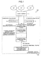
- Fig. 1 is an explanatory diagram explaining the concept of abnormal traffic detection according to a first embodiment
- FIG. 1 is an explanatory diagram explaining the concept of the abnormal traffic detection according to the first embodiment.
- An abnormal traffic detection system 200 is a system that monitors packets being transmitted and received between ISPs and detects an abnormal traffic (such as abnormal traffic due to the DDoS attack) at the IX (server or network).
- a layer 2 switch 11 performs a relay process on the packets being transmitted and received between the ISPs 1 to x (X is a natural number).
- An abnormal traffic detection apparatus 100 which performs an abnormal traffic detection process, monitors traffics passing through the layer 2 switch 11 when the traffics are transmitted and received between the ISPs 1 to x that are connected to the Internet via the layer 2 switch 11.
- the abnormal traffic detection apparatus 100 uses information (traffic information) on the monitored traffics to detect an abnormal traffic toward the ISPs 1 to x.
- the abnormal traffic detection apparatus 100 acquires (receives) an sFlow packet 51 as the information on the traffics flowing through the layer 2 switch 11 (1). Then, the abnormal traffic detection apparatus 100 uses a destination MAC address and VLAN information contained in the received sFlow packet 51 to count the traffics in each corresponding ISP through which the traffics are to be routed. At this time, the abnormal traffic detection apparatus 100 creates counter tables (amount information tables for counting information on the amount of traffics) 50 corresponding to the ISPs 1 to x and counts the traffics per destination IP address in each of the counter tables (2).
- the abnormal traffic detection apparatus 100 compares the information on the amount of traffics stored in the counter tables (the number of packets or packet size) (amount information) with traffic threshold values that are set for the respective counter tables (3) to detect an abnormal traffic (4).
- the abnormal traffic detection apparatus 100 acquires an sFlow packet 52 as a new sFlow packet (5).
- the abnormal traffic detection apparatus 100 identifies the counter table corresponding to the sFlow packet 52 and retrieves the destination IP address (retrieves a registration position) corresponding to the sFlow packet 52 from the identified counter table (6).
- the abnormal traffic detection apparatus 100 counts (adds) the traffics by incrementing the existing counter by 1.
- the abnormal traffic detection apparatus 100 newly registers the destination IP address corresponding to the sFlow packet 52 in the counter table corresponding to the sFlow packet 52 and counts the traffics (7).
- the count values of traffics are stored in the counter tables corresponding to each of the ISPs.
- one memory area for storing the count values of the traffics therein is smaller than a memory area for collectively storing the count values of all the traffics in one counter table.
- the size of the memory area for storing count values of traffics therein is N
- the size of the memory area for collectively storing the count values of all the traffics is xN.
- the destination IP address can be rapidly retrieved when a judgment is made as to whether each traffic is registered in the counter table.
- an abnormal traffic occurring in the IX can be efficiently and rapidly detected.
- Fig. 2 is a diagram illustrating a structure of an abnormal traffic detection system equipped with the abnormal traffic detection apparatus according to the first embodiment of the invention.
- the abnormal traffic detection system 200 comprises the ISPs 1 to 4, the layer 2 switch 11 connected to the ISPs 1 to 4 via representative routers (not shown) of each of the ISPs 1 to 4, and the abnormal traffic detection apparatus 100 connected to the layer 2 switch 11.
- the IX as an observation point of the traffics is configured with the layer 2 switch 11 and the representative routers of the respective ISPs 1 to 4.
- Each of the ISPs 1 to 4 is a communication apparatus for making communication with other ISPs via the layer 2 switch 11.
- the abnormal traffic detection apparatus 100 has a traffic information transmitting unit 30 connected to the layer 2 switch 11, and an abnormal traffic analyzing unit 20 connected to the traffic information transmitting unit 30.
- the traffic information transmitting unit 30 monitors the traffics flowing through the layer 2 switch 11 and transmits the information on the monitored traffics as sFlow packet to the abnormal traffic analyzing unit 20.
- the abnormal traffic analyzing unit 20 receives the sFlow packet transmitted from the traffic information transmitting unit 30 and analyzes the contents of the received sFlow packet to detect an abnormal traffic.
- FIG. 3 is a block diagram illustrating the structure of the abnormal traffic analyzing unit.
- the abnormal traffic analyzing unit 20 has a traffic separating unit (storage controlling unit) 21, destination IP address counting units (amount information storing units) C1 to C4, and abnormal traffic judging units J1 to J4.
- the destination IP address counting units C1 to C4 are connected to the traffic separating unit 21.
- the abnormal traffic judging unit J1 is connected to the destination IP address counting unit C1 and the abnormal traffic judging unit J2 is connected to the destination IP address counting unit C2.
- the abnormal traffic judging unit J3 is connected to the destination IP address counting unit C3 and the abnormal traffic judging unit J4 is connected to the destination IP address counting unit C4.
- the destination IP address counting units and the abnormal traffic judging units are arranged as many as the ISPs connected to the IX. Since the abnormal traffic detection system 200 according to the present embodiment comprises four ISPs, four destination IP address counting units and four abnormal traffic judging units are provided.
- the destination IP address counting unit C1 corresponds to the ISP1 and the destination IP address counting unit C2 corresponds to the ISP2.
- the destination IP address counting unit C3 corresponds to the ISP3 and the destination IP address counting unit C4 corresponds to the ISP4.
- the traffic separating unit 21 separates the traffics on the basis of the ISPs through which the traffics are to be routed. Specifically, the traffic separating unit 21 sequentially reads frame samples (such as Ether (trademark) frames) contained in the received sFlow packet from the beginning of the frame samples, for example. The traffic separating unit 21 extracts the destination MAC address and the destination VLAN from the read frame samples. Also, the traffic separating unit 21 extracts the destination IP address and the frame sample size from the read frame sample.
- frame samples such as Ether (trademark) frames
- the traffic separating unit 21 retrieves the ISP corresponding to the combination of the extracted MAC address and VLAN from IX management information described later (information on the representative routers of the ISPs managed by the IX).
- the traffic separating unit 21 transmits the extracted destination IP address and the frame sample size to the destination IP address counting unit (any one of the destination IP address counting units C1 to C4) corresponding to the retrieved ISP.
- the destination IP address counting units C1 to C4 hold the counter tables 101 to 104 described later (information tables for storing the number of times of appearance of the frame samples corresponding to the destination IP address or their size), respectively.
- the destination IP address counting units C1 to C4 retrieve the destination IP address received from the traffic separating unit 21 from their own counter tables, respectively.
- the destination IP address (index, described later) to be retrieved is not present in the counter tables, the destination IP address counting units C1 to C4 add an index to be retrieved to the index in their own counter tables, respectively.
- the destination IP address counting units C1 to C4 use the received information to update their own counter tables, respectively.
- the abnormal traffic judging units J1 to J4 analyze the contents of the sFlow packet, which has been received from the IX by the abnormal traffic analyzing unit 20, to detect an abnormal traffic. Specifically, the abnormal traffic judging units J1 to J4 compare a "counter" value of each index in the counter tables 101 to 104 monitored by the abnormal traffic judging units J1 to J4 with threshold value information (information on the threshold value used for judging the abnormal traffic detection) previously stored in the judging units at predetermined intervals (for each constant period, for example), respectively. The abnormal traffic judging units J1 to J4 detect an abnormal traffic on the basis of the comparison result.
- threshold value information information on the threshold value used for judging the abnormal traffic detection
- the traffic information transmitting unit 30 of the abnormal traffic detection apparatus 100 monitors the traffics flowing through the layer 2 switch 11. Then, the traffic information transmitting unit 30 transmits the information on the monitored traffics as an sFlow packet to the abnormal traffic analyzing unit 20.
- An operation of the abnormal traffic analyzing unit 20 when the sFlow packet is transmitted from the traffic information transmitting unit 30 to the abnormal traffic analyzing unit 20 will be described. At first, a process of counting the destination IP addresses on the basis of the frame samples contained in the sFlow packet will be described and then an abnormal traffic detection process will be described.
- Fig. 4 is a flowchart illustrating a procedure of the destination IP address count process.
- the abnormal traffic analyzing unit 20 receives the sFlow packet transmitted from the layer 2 switch 11 of the IX via the traffic information transmitting unit 30 (step S110).
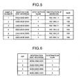
- Fig. 5 is a diagram illustrating one example of the sFlow packet transmitted from the layer 2 switch.
- the sFlow packet includes one or more frame samples (sFlow packet samples), where each frame sample is associated with "sample number”, “destination MAC address”, “destination VLAN”, “destination IP address” and "size”.
- sample number is information for identifying the frame samples and the "destination MAC address” is a destination MAC (Media Access Control) address of the frame sample.
- destination VLAN is information for identifying a VLAN (Virtual Local Area Network) as the destination of the frame sample and the "destination IP address” is a destination IP address of the frame sample.
- size is a size of the frame sample.
- the frame sample having the "sample number" of "1” has the "destination MAC address” of "0000.0000.0001" and the “destination VLAN” of "1".
- the "destination IP address” of the frame sample is "192.168.1.1” and the "size” thereof is “100”.
- the abnormal traffic analyzing unit 20 transmits the sFlow packet to the traffic separating unit 21.
- the traffic separating unit 21 sequentially reads the frame samples contained in the received sFlow packet from the beginning of the frame samples.
- the traffic separating unit 21 reads the frame sample having the "sample number" of "1" from the sFlow packet (step S120). The traffic separating unit 21 extracts the destination MAC address and the destination VLAN from the read frame sample. Then, the traffic separating unit 21 retrieves the ISP corresponding to (matching with) the combination of the extracted MAC address and VLAN from the IX management information indicated in Fig. 6 .
- Fig. 6 is a diagram illustrating a structure of the IX management information.
- the IX management information is a list (information table) of "MAC address” and "destination VLAN” of the representative routers of the ISPs 1 to 4 illustrated in Fig. 2 , where "ISP", "destination MAC address” and “destination VLAN” are associated with one another.
- the "ISP” is information for identifying the ISPs.
- the ISP having the "ISP” of "1” is the ISP1 and the ISP having the "ISP” of "2" is the ISP2.
- the ISP having the "ISP" of "3” is the ISP3 and the ISP having the "ISP” of "4" is the ISP4.
- the "destination MAC address" and the “destination VLAN” of the IX management information are the MAC address and the VLAN of an interface of the representative router as a connection point that is used when the ISPs 1 to 4 are connected to the IX.
- the "destination MAC address” and the “destination VLAN” are information utilized by the IX for customer management (management of the ISPs 1 to 4 connected to the IX).
- the frame sample having the "sample number” of "1” has the "destination MAC address" of "0000.0000.0001” and the “destination VLAN” of "1".
- the traffic separating unit 21 retrieves the ISP matching with the "destination MAC address" and the "destination VLAN” from the IX management information. As indicated in the IX management information of Fig. 6 , the ISP having the "destination MAC address" of "0000.0000.0001" and the "destination VLAN” of "1” is the ISP1. Thus, the traffic separating unit 21 judges that the frame sample having the "sample number" of "1” is the traffic toward the ISP1 (the ISP to be routed is the ISP1). Then, the traffic separating unit 21 associates the traffic having the "sample number” of "1” with the ISP1.
- the traffic separating unit 21 extracts the "destination IP address” and the "size” as the information on the frame sample having the “sample number” of “1” from the sFlow packet. Thereby, the traffic separating unit 21 separates (extracts) the traffic having the "sample number” of "1” as the traffic of the ISP1 from the sFlow packet (step S130).
- the traffic separating unit 21 transmits the "destination IP address" of "192.168.1.1” and the "size” of "100” as the information on the frame sample having the "sample number” of "1” to the destination IP address counting unit C1 (the destination IP address counting unit corresponding to the ISP1).
- the destination IP address counting unit C1 receives the "destination IP address" of "192.168.1.1” and the "size” of "100” from the traffic separating unit 21.
- the destination IP address counting units C1 to C4 hold the counter tables 101 to 104 illustrated in Figs. 7 to 10 , respectively.
- Each of the counter tables 101 to 104 stored in the destination IP address counting units C1 to C4 is an independent table.
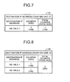
- the counter table 101 indicated in Fig. 7 is the counter table of the destination IP address counting unit C1 and the counter table 102 indicated in Fig. 8 is the counter table of the destination IP address counting unit C2.
- the counter table 103 indicated in Fig. 9 is the counter table of the destination IP address counting unit C3 and the counter table 104 indicated in Fig. 10 is the counter table of the destination IP address counting unit C4.
- the counter tables 101 to 104 indicated in Figs. 7 to 10 are an information table storing therein the "destination IP address" (index), and the number of times of appearance of the frame sample and the total size corresponding to the index.
- Each of the counter tables 101 to 104 stores therein the number of times of appearance of each index (value of "counter”) and the “size” of the frame sample corresponding to each index per index and stores therein the total number of times of appearance of all the indexes (value of "total counter”) and the “total size” of all the indexes.
- the counter table 101 indicated in Fig. 7 indicates that the "counter” having the "destination IP address” of "192.168.1.1” is “1" and its "size” is “100".
- the counter table 101 indicates that the "total counter” having the "destination IP address” of "192.168.1.1” is “1” and its “total size” is "100”.
- the destination IP address counting units C1 to C4 add a new index to the counter tables 101 to 104 when receiving a new "destination IP address" from the traffic separating unit 21, respectively.
- the destination IP address counting unit C1 retrieves the "destination IP address" of "192.168.1.1” received from the traffic separating unit 21 from the index in its own counter table (the counter table 101 indicated in Fig. 7 ).
- the destination IP address counting unit C1 adds the index to be retrieved to the index of its own counter table 101.
- the destination IP address counting unit C1 adds "192.168.1.1" to the index of the counter table 101.
- the destination IP address counting unit C1 associates "1" of the "counter” and "100” of the "size” with the added index and stores them in the counter table 101.
- the destination IP address counting unit C1 increments the value of the “total counter” by 1 to be “1”, and sets the “total size” be "100”.
- the destination IP address counting unit C1 associates "1" of the "total counter” and "100” of the "total size” with the added index and stores them in the counter table 101 (step S140).
- the state of the counter table stored in the destination IP address counting unit C1 is the counter table 101 indicated in Fig. 7 .
- the traffic separating unit 21 judges whether the destination IP address has been counted for all the frame samples contained in the received sFlow packet (step S150).
- the traffic separating unit 21 reads the frame sample having the next "sample number" from the sFlow packet.
- the traffic separating unit 21 reads the frame sample having the "sample number" of "2" from the sFlow packet (step S120).
- the traffic separating unit 21 extracts the destination MAC address and the destination VLAN from the read frame sample.
- the traffic separating unit 21 retrieves the ISP matching with the combination of the extracted MAC address and VLAN from the IX management information indicated in Fig. 6 .
- the frame sample having the “sample number" of “2” has the "destination MAC address” of "0000.0000.0002" and the “destination VLAN” of "1".
- the traffic separating unit 21 retrieves the ISP matching with the "destination MAC address” and the "destination VLAN” from the IX management information.
- the ISP having the "destination MAC address" of "0000.0000.0002" and the "destination VLAN” of "1” is the ISP2.
- the traffic separating unit 21 judges that the frame sample having the "sample number" of "2" is the traffic toward the ISP2 (the ISP to be routed is the ISP2). Then, the traffic separating unit 21 associates the traffic having the "sample number" of "2" with the ISP2.
- the traffic separating unit 21 extracts the "destination IP address" and the "size” as the information on the frame sample having the "sample number” of "2" from the sFlow packet. Thereby, the traffic separating unit 21 separates the traffic having the "sample number” of "2” as the traffic of the ISP2 from the sFlow packet (step S130).
- the traffic separating unit 21 transmits "192.168.2.1” of the "destination IP address” and "100" of the "size” as the information on the frame sample having the "sample number” of "2” to the destination IP address counting unit C2 (the destination IP address counting unit corresponding to the ISP2).
- the destination IP address counting unit C2 receives "192.168.2.1” of the "destination IP address” and "100" of the "size” from the traffic separating unit 21.
- the destination IP address counting unit C2 retrieves "192.168.2.1” of the "destination IP address” received from the traffic separating unit 21 from among the indexes of its own counter table.
- the destination IP address counting unit C2 adds the index to be retrieved to the index of its own counter table 102.
- the destination IP address counting unit C2 Since no index is present in the counter table 102 in the initial state, the destination IP address counting unit C2 adds "192.168.2.1" to the index of the counter table 102.
- the destination IP address counting unit C2 associates "1" of the "counter” and "100” of the "size” with the added index and stores them in the counter table 102.
- the destination IP address counting unit C2 increments the value of the "total counter” by 1 to be “1” and sets the “total size” be "100”. Then, the destination IP address counting unit C2 associates "1" of the "total counter” and "100” of the "total size” with the added index and stores them in the counter table 102 (step S140).
- the traffic separating unit 21 judges whether the destination IP address has been counted for all the frame samples contained in the received sFlow packet (step S150).
- the traffic separating unit 21 reads the frame sample having the next "sample number" from the sFlow packet.
- the traffic separating unit 21 reads the frame sample having the "sample number" of "3" from the sFlow packet (step S120).
- the traffic separating unit 21 extracts the destination MAC address and the destination VLAN from the read frame sample.
- the traffic separating unit 21 retrieves the ISP matching with the combination of the extracted MAC address and VLAN from the IX management information indicated in Fig. 6 .
- the frame sample having the “sample number" of “3” has the "destination MAC address” of "0000.0000.0003” and the “destination VLAN” of "2".
- the traffic separating unit 21 retrieves the ISP matching with the "destination MAC address” and the "destination VLAN” from the IX management information.
- the ISP having the "destination MAC address" of "0000.0000.0003" and the "destination VLAN” of "2" is the ISP4.
- the traffic separating unit 21 judges that the frame sample having the "sample number" of "3" is the traffic toward the ISP4 (the ISP to be routed is the ISP4). Then, the traffic separating unit 21 associates the traffic having the "sample number" of "3" with the ISP4.
- the traffic separating unit 21 extracts the "destination IP address" and the "size” as the information on the frame sample having the "sample number” of "3” from the sFlow packet. Thereby, the traffic separating unit 21 separates the traffic having the "sample number” of "3” as the traffic of the ISP4 from the sFlow packet (step S130).
- the traffic separating unit 21 transmits "192.168.3.1” of the "destination IP address” and "100" of the "size” as the information on the frame sample having the "sample number” of "3” to the destination IP address counting unit C4 (the destination IP address counting unit corresponding to the ISP4).
- the destination IP address counting unit C4 receives "192.168.3.1” of the "destination IP address” and "100" of the "size” from the traffic separating unit 21.
- the destination IP address counting unit C4 retrieves "192.168.3.1” of the "destination IP address” received from the traffic separating unit 21 from the indexes of its own counter table.
- the destination IP address counting unit C4 adds the index to be retrieved to the indexes of its own counter table 104.
- the destination IP address counting unit C4 adds "192.168.3.1" to the index of the counter table 104.
- the destination IP address counting unit C4 associates "1" of the "counter” and "100” of the "size” with the added index and stores the same in the counter table 104.
- the destination IP address counting unit C4 increments the value of the "total counter” by 1 to be “1” and sets the “total size” be "100”.
- the destination IP address counting unit C4 associates "1" of the "total counter” and "100” of the "total size” with the added index and stores them in the counter table 104 (step S140).
- the state of the counter table stored in the destination IP address counting unit C4 is the counter table 104 indicated in Fig. 10 .
- the traffic separating unit 21 judges whether the destination IP address has been counted for all the frame samples contained in the received sFlow packet (step S150).
- the traffic separating unit 21 reads the frame sample having the next "sample number" from the sFlow packet.
- the traffic separating unit 21 reads the frame sample having the "sample number” of "4" from the sFlow packet (step S120).
- the traffic separating unit 21 extracts the destination MAC address and the destination VLAN from the read frame sample.
- the traffic separating unit 21 retrieves the ISP matching with the combination of the extracted MAC address and VLAN from the IX management information indicated in Fig. 6 .
- the frame sample having the “sample number” of "4" has the "destination MAC address” of "0000.0000.0002" and the “destination VLAN” of "1".
- the traffic separating unit 21 retrieves the ISP matching with the "destination MAC address” and the "destination VLAN” from the IX management information.
- the ISP having the "destination MAC address" of "0000.0000.0002" and the "destination VLAN” of "1" is the ISP2.
- the traffic separating unit 21 judges that the frame sample having the "sample number” of "4" is the traffic toward the ISP2 (the ISP to be routed is the ISP2). Then, the traffic separating unit 21 associates the traffic having the "sample number" of "4" with the ISP2.
- the traffic separating unit 21 extracts the "destination IP address" and the "size” as the information on the frame sample having the "sample number” of "4" from the sFlow packet. Thereby, the traffic separating unit 21 separates the traffic having the "sample number” of "4" as the traffic of the ISP2 from the sFlow packet (step S130).
- the traffic separating unit 21 transmits "192.168.2.2" of the "destination IP address” and "100" of the "size” as the information on the frame sample having the "sample number” of "4" to the destination IP address counting unit C2 (the destination IP address counting unit corresponding to the ISP2).
- the destination IP address counting unit C2 receives "192.168.2.2” of the "destination IP address” and "100" of the "size” from the traffic separating unit 21.
- the destination IP address counting unit C2 retrieves "192.168.2.2” of the "destination IP address” received from the traffic separating unit 21 from the indexes of its own counter table (the counter table 102 indicated in Fig. 8 ).
- the destination IP address counting unit C2 adds "192.168.2.2” to the index in the counter table 102. Further, the destination IP address counting unit C2 associates "1" of the "counter” and “100” of the "size” with the added index and stores (adds) them in the counter table 102. In addition, the destination IP address counting unit C2 increments the value of the "total counter” by 1 to be “2” and adds 100 to the "total size" to be "200".
- the destination IP address counting unit C2 associates "2" of the "total counter” and "200" of the “total size” with the added index and stores (overwrites) them in the counter table 102 (step S140).
- the state of the counter table stored in the destination IP address counting unit C2 is the counter table 102 indicated in Fig. 8 .
- the traffic separating unit 21 judges whether the destination IP address has been counted for all the frame samples contained in the received sFlow packet (step S150).
- the traffic separating unit 21 reads the frame sample having the next "sample number" from the sFlow packet.
- the traffic separating unit 21 reads the frame sample having the "sample number” of "5" from the sFlow packet (step S120).
- the traffic separating unit 21 extracts the destination MAC address and the destination VLAN from the read frame sample.
- the traffic separating unit 21 retrieves the ISP matching with the combination of the extracted MAC address and VLAN from the IX management information indicated in Fig. 6 .
- the frame sample having the “sample number” of "5" has the "destination MAC address” of "0000.0000.0003" and the “destination VLAN” of "1".
- the traffic separating unit 21 retrieves the ISP matching with the "destination MAC address” and the "destination VLAN” from the IX management information.
- the ISP having the "destination MAC address" of "0000.0000.0003" and the "destination VLAN” of "1" is the ISP3.
- the traffic separating unit 21 judges that the frame sample having the "sample number” of "5" is the traffic toward the ISP3 (the ISP to be routed is the ISP3). Then, the traffic separating unit 21 associates the traffic having the "sample number" of "5" with the ISP3.
- the traffic separating unit 21 extracts the "destination IP address" and the "size” as the information on the frame sample having the "sample number” of "5" from the sFlow packet. Thus, the traffic separating unit 21 separates the traffic having the "sample number” of "5" as the traffic of the ISP3 from the sFlow packet (step S130). The traffic separating unit 21 transmits "192.168.3.2” of the "destination IP address” and "100" of the "size” as the information on the frame sample having the "sample number” of "5" to the destination IP address counting unit C3 (the destination IP address counting unit corresponding to the ISP3).
- the destination IP address counting unit C3 receives "192.168.3.2” of the "destination IP address” and "100" of the "size” from the traffic separating unit 21.
- the destination IP address counting unit C4 retrieves "192.168.3.2” of the "destination IP address” received from the traffic separating unit 21 from the index in its own counter table.
- the destination IP address counting unit C3 adds the index to be retrieved to the index in its own counter table 103.
- the destination IP address counting unit C3 Since no index is present in the counter table 103 in the initial state, the destination IP address counting unit C3 adds "192.168.3.2" to the index in the counter table 103.
- the destination IP address counting unit C3 associates "1" of the "counter” and “100” of the "size” with the added index and stores them in the counter table 103. Further, the destination IP address counting unit C3 increments the value of the "total counter” by 1 to be “1” and sets the “total size” be “100”. Then, the destination IP address counting unit C3 associates "1" of the "total counter” and "100” of the "total size” with the added index and stores them in the counter table 103 (step S140).
- the traffic separating unit 21 judges whether the destination IP address has been counted for all the frame samples contained in the received sFlow packet (step S150).
- the traffic separating unit 21 reads the frame sample having the next "sample number" from the sFlow packet.
- the traffic separating unit 21 reads the frame sample having the "sample number" of "6" from the sFlow packet (step S120).
- the traffic separating unit 21 extracts the destination MAC address and the destination VLAN from the read frame sample.
- the traffic separating unit 21 retrieves the ISP matching with the combination of the extracted MAC address and VLAN from the IX management information indicated in Fig. 6 .
- the frame sample having the “sample number" of “6” has the "destination MAC address” of "0000.0000.0003" and the “destination VLAN” of "1".
- the traffic separating unit 21 retrieves the ISP matching with the "destination MAC address” and the "destination VLAN” from the IX management information.
- the ISP having the "destination MAC address" of "0000.0000.0003" and the "destination VLAN” of "1" is the ISP3.
- the traffic separating unit 21 judges that the frame sample having the "sample number" of "6" is the traffic toward the ISP3 (the ISP to be routed is the ISP3). Then, the traffic separating unit 21 associates the traffic having the "sample number" of "6" with the ISP3.
- the traffic separating unit 21 extracts the "destination IP address" and the "size” as the information on the frame sample having the “sample number” of “6” from the sFlow packet. Thereby, the traffic separating unit 21 separates the traffic having the "sample number” of “6” as the traffic of the ISP3 from the sFlow packet (step S130).
- the traffic separating unit 21 transmits "192.168.3.2” of the "destination IP address” and "100" of the "size” as the information on the frame sample having the "sample number” of “6” to the destination IP address counting unit C3 (the destination IP address counting unit corresponding to the ISP3).
- the destination IP address counting unit C3 receives "192.168.3.2” of the "destination IP address” and "100" of the "size” from the traffic separating unit 21.
- the destination IP address counting unit C3 retrieves "192.168.3.2” of the "destination IP address” received from the traffic separating unit 21 from the index in its own counter table 103.
- the destination IP address counting unit C3 can extract "192.168.3.2” of the "destination IP address” from the counter table 103.
- the destination IP address counting unit C3 increments the "counter” of the frame sample corresponding to the extracted index by 1 to be “2” and adds 100 to the "size” of the frame sample corresponding to the extracted index to be "200". Then, the destination IP address counting unit C3 associates "2" of the "counter” and "200” of the "size” with the extracted index and stores (overwrites) them in the counter table 103.
- the destination IP address counting unit C3 increments the value of the "total counter” by 1 to be “2” and adds 100 to the "total size” to be “200”. Then, the destination IP address counting unit C3 associates "2" of the “total counter” and “200” of the “total size” with the added index and stores (overwrites) them in the counter table 103 (step S140). At this time, the state of the counter table stored in the destination IP address counting unit C3 is the counter table 103 indicated in Fig. 9 . Following that, the abnormal traffic analyzing unit 20 repeats the processes of steps S120 to S150 each time an sFlow packet is received.
- the abnormal traffic analyzing unit 20 shifts to a state for waiting for a new sFlow packet. Thereafter, the abnormal traffic judging units J1 to J4 analyzes the contents of the sFlow packet that has been received by the abnormal traffic analyzing unit 20 from the IX to detect an abnormal traffic.
- Fig. 11 is a flowchart illustrating a procedure of the abnormal traffic detection process.
- the abnormal traffic judging units J1 to J4 compare the value of the "counter" of each index of their own counter tables 101 to 104 with the threshold value information previously stored in the abnormal traffic judging units J1 to J4 at predetermined intervals (for each constant period, for example).
- the abnormal traffic judging unit J1 compares the value of the "counter” of each index stored in the destination IP address counting unit C1 with the previously-held threshold value (threshold value information indicated in Fig. 12 ).
- the abnormal traffic judging unit J2 compares the value of the "counter” of each index stored in the destination IP address counting unit C2 with the previously-held threshold value (threshold value information indicated in Fig. 13 ).
- the abnormal traffic judging unit J3 compares the value of the "counter” of each index stored in the destination IP address counting unit C3 with the previously-held threshold value (threshold value information indicated in Fig. 14 ).
- the abnormal traffic judging unit J4 compares the value of the "counter” of each index stored in the destination IP address counting unit C4 with the previously-held threshold value (threshold value information indicated in Fig. 15 ) (step S210).
- Fig. 12 is a diagram illustrating a structure of the threshold value information stored in the abnormal traffic judging unit J1 and Fig. 13 is a diagram illustrating a structure of the threshold value information stored in the abnormal traffic judging unit J2.
- Fig. 14 is a diagram illustrating a structure of the threshold value information stored in the abnormal traffic judging unit J3 and Fig. 15 is a diagram illustrating a structure of the threshold value information stored in the abnormal traffic judging unit J4.
- the threshold value information indicated in Figs. 12 to 15 are information tables in which the "counter threshold value” and the “total counter threshold value” are associated with each other.
- the "counter threshold value” is a threshold value to be compared with the value of the "counter” (the value of the "counter” indicated in Figs. 7 to 10 ) of the frame samples counted by the destination IP address counting units C1 to C4.
- the "size threshold value” as the threshold value of the frame sample size is associated with the “counter threshold value”.
- the “total counter threshold value” is a threshold value to be compared with the sum of the values of the "counter” of the frame samples (the values of the "total counter” indicated in Figs. 7 to 10 ).
- the “total size threshold value” as the threshold value of the “total size” of the frame sample is associated with the “total counter threshold value”.
- the threshold value information indicated in Fig. 12 has the “counter threshold value” of “2" and the “size threshold value” of "200". Further, the “total counter threshold value” is “2” and the “total size threshold value” is “200”.
- the abnormal traffic judging units J1 to J4 detect an abnormal traffic on the basis of the comparison result between the counter tables 101 to 104 stored in the destination IP address counting units C1 to C4 and the threshold value information previously stored in the abnormal traffic judging units J1 to J4.
- the abnormal traffic judging units J1 to J4 judge that an abnormal traffic is present when the value of the "counter” or the value of the "size” for the index exceeds the "counter threshold value” or the “size threshold value” or when the value of the "total counter” or the value of the "total size” for the index exceeds the "total counter threshold value” or the "total size threshold value", for example.
- the abnormal traffic judging units J1 to J4 After reading the value of the "counter”, the value of the "size”, the value of the “total counter”, and the value of the "total size” for the index from the destination IP address counting units C1 to C4, the abnormal traffic judging units J1 to J4 cause the destination IP address counting units C1 to C4 to clear the values of the counter tables 101 to 104, respectively (step S220).
- the abnormal traffic judging units J1 to J4 judge whether an abnormal traffic is present, and then shifts to the standby state until a predetermined time elapses (step S230, No).
- the abnormal traffic judging units J1 to J4 compare the value of each index of their own counter tables 101 to 104 with their own previously-held threshold value information (step S210).
- the abnormal traffic judging units J1 to J4 repeat the processes of steps S210 to S230.
- the abnormal traffic judging unit J1 reads the value "1" of the "counter” and the value "100" of the "size” for the index "192.168.1.1” from the counter table 101 stored in the destination IP address counting unit C1.
- the abnormal traffic judging unit J1 compares the "counter threshold value” of "2", which is stored in itself and is indicated in Fig. 12 , with the "counter” value of "1” read from the destination IP address counting unit C1. In addition, the abnormal traffic judging unit J1 compares the "size threshold value" of "200” with the size of "100” read from the destination IP address counting unit C1.
- the value of the "counter” read from the destination IP address counting unit C1 by the abnormal traffic judging unit J1 is smaller than the "counter threshold value” stored in the abnormal traffic judging unit J1.
- the value of the "size” read from the destination IP address counting unit C1 by the abnormal traffic judging unit J1 is smaller than the value of the "size threshold value” stored in the abnormal traffic judging unit J1.
- abnormal traffic judging unit J1 reads the value "1" of the “total counter” and the value "100” of the “total size” for the index "192.168.1.1” from the counter table 101 stored in the destination IP address counting unit C1.
- the abnormal traffic judging unit J1 compares the "total counter threshold value" of "2" indicated in Fig. 12 with the “total counter” of “1” read from the destination IP address counting unit C1. In addition, the abnormal traffic judging unit J1 compares the "total size threshold value" of "200” with the “total size” of "100” read from the destination IP address counting unit C1.
- the value of the "total counter” read from the destination IP address counting unit C1 by the abnormal traffic judging unit J1 is smaller than the "total counter threshold value" stored in the abnormal traffic judging unit J1.
- the value of the "total size” read from the destination IP address counting unit C1 by the abnormal traffic judging unit J1 is smaller than the "total size threshold value” stored in the abnormal traffic judging unit J1.
- the abnormal traffic judging unit J2 reads the value "1" of the "counter” and the value "100” of the "size” for the index "192.168.2.1” from the counter table 102 stored in the destination IP address counting unit C2.
- the abnormal traffic judging unit J2 compares the "counter threshold value” of "2" indicated in Fig. 13 with the value “1" of the "counter” read from the destination IP address counting unit C2.
- the abnormal traffic judging unit J1 compares the "size threshold value” of "200” with the value "100” of the "size” read from the destination IP address counting unit C1.
- the value of the "counter” for the index "192.168.2.1” read from the destination IP address counting unit C2 by the abnormal traffic judging unit J2 is smaller than the "counter threshold value” stored in the abnormal traffic judging unit J2.
- the value of the "size” for the index "192.168.2.1” read from the destination IP address counting unit C2 by the abnormal traffic judging unit J2 is smaller than the "size threshold value” stored in the abnormal traffic judging unit J1.
- the abnormal traffic judging unit J2 reads the value "2" of the "counter” and the value "100” of the "size” for the index "192.168.2.2” from the counter table 102 stored in the destination IP address counting unit C2.
- the abnormal traffic judging unit J2 compares the "counter threshold value” of "2" indicated in Fig. 13 with the value “1" of the "counter” read from the destination IP address counting unit C2. In addition, the abnormal traffic judging unit J2 compares the "size threshold value” of "200” with the value "100” of the "size” read from the destination IP address counting unit C2.
- the value of the "counter” for the index "192.168.2.2” read from the destination IP address counting unit C2 by the abnormal traffic judging unit J2 is smaller than the "counter threshold value" stored in the abnormal traffic judging unit J2.
- the "size” for the index "192.168.2.2” read from the destination IP address counting unit C2 by the abnormal traffic judging unit J2 is smaller than the "size threshold value" stored in the abnormal traffic judging unit J1.
- the abnormal traffic judging unit J2 reads the value "2" of the "total counter” and the value "200" of the "total size” for the index "192.168.2.1” and the index "192.168.2.2” from the counter table 102 stored in the destination IP address counting unit C2.
- the abnormal traffic judging unit J2 compares the "total counter threshold value" of "2” indicated in Fig. 12 with the “total counter” of “2” read from the destination IP address counting unit C2. In addition, the abnormal traffic judging unit J2 compares the "total size threshold value" of "200” with the “total size” of "200” read from the destination IP address counting unit C2.
- the value of the "total counter” read from the destination IP address counting unit C2 by the abnormal traffic judging unit J2 is equal to or larger than the value of the "total counter threshold value” stored in the abnormal traffic judging unit J2.
- the value of the "total size” read from the destination IP address counting unit C2 by the abnormal traffic judging unit J2 is equal to or larger than the value of the "total size threshold value” stored in the abnormal traffic judging unit J2.
- the abnormal traffic judging unit J2 judges that an abnormal traffic has occurred in the IX (detects an abnormal traffic). In this case, the abnormal traffic judging unit J2 judges that the contents of the abnormal traffic indicate that "the number of packets toward the ISP2 and the packet size are excessive".
- the abnormal traffic judging unit J3 reads the value "2" of the "counter” and the "size” of "200” for the index "192.168.3.2” from the counter table 103 stored in the destination IP address counting unit C3.
- the abnormal traffic judging unit J3 compares the "counter threshold value” of "2" indicated in Fig. 14 with the value “2" of the "counter” read from the destination IP address counting unit C3. In addition, the abnormal traffic judging unit J3 compares the "size threshold value" of "200” with the "size” of "200” read from the destination IP address counting unit C3.
- the value of the "counter” for the index "192.168.3.2” read from the destination IP address counting unit C3 by the abnormal traffic judging unit J3 is equal to or larger than the value of the "counter threshold value” stored in the abnormal traffic judging unit J3.
- the value of the "size” for the index "192.168.3.2” read from the destination IP address counting unit C3 by the abnormal traffic judging unit J3 is equal to or larger than the value of the "size threshold value" stored in the abnormal traffic judging unit J3.
- the abnormal traffic judging unit J3 reads the value "2" of the "total counter” and the value "200" of the "total size” for the index "192.168.3.2” from the counter table 103 stored in the destination IP address counting unit C3.
- the abnormal traffic judging unit J3 compares the "total counter threshold value" of "10" indicated in Fig. 14 with the “total counter” of "2" read from the destination IP address counting unit C3. In addition, the abnormal traffic judging unit J3 compares the "total size threshold value" of "800” with the “total size” of "200” read from the destination IP address counting unit C3.
- the value of the "total counter” read from the destination IP address counting unit C3 by the abnormal traffic judging unit J3 is smaller than the "total counter threshold value" stored in the abnormal traffic judging unit J3.
- the value of the "total size” read from the destination IP address counting unit C3 by the abnormal traffic judging unit J3 is smaller than the value of the "total size threshold value” stored in the abnormal traffic judging unit J3.
- the abnormal traffic judging unit J3 judges that an abnormal traffic has occurred in the IX. In this case, the abnormal traffic judging unit J3 judges that the contents of the abnormal traffic indicate that "the number of packets for the index "192.168.3.2" and the packet size are excessive".
- the abnormal traffic judging unit J4 reads the value "1" of the "counter” and the value "100” of the "size” for the index "192.168.3.1” from the counter table 104 stored in the destination IP address counting unit C4.
- the abnormal traffic judging unit J4 compares the "counter threshold value” of "5" indicated in Fig. 15 with the value “1" of the "counter” read from the destination IP address counting unit C4. In addition, the abnormal traffic judging unit J4 compares the "size threshold value” of "500” with the "size” of "100” read from the destination IP address counting unit C4.
- the value of the "counter” read from the destination IP address counting unit C4 by the abnormal traffic judging unit J4 is smaller than the "counter threshold value” stored in the abnormal traffic judging unit J4.
- the value of the "size” read from the destination IP address counting unit C4 by the abnormal traffic judging unit J4 is smaller than the "size threshold value” stored in the abnormal traffic judging unit J4.
- the abnormal traffic judging unit J4 reads the value "1" of the “total counter” and the value "100” of the “total size” for the index "192.168.3.1” from the counter table 104 stored in the destination IP address counting unit C4.
- the abnormal traffic judging unit J4 compares the "total counter threshold value” of "5" indicated in Fig. 15 with the value “1" of the “total counter” read from the destination IP address counting unit C4. In addition, the abnormal traffic judging unit J4 compares the "total size threshold value" of "500” with the value "100” of the “total size” read from the destination IP address counting unit C4.
- the value of the "total counter” read from the destination IP address counting unit C4 by the abnormal traffic judging unit J4 is smaller than the "total counter threshold value" stored in the abnormal traffic judging unit J4.
- the value of the "total size” read from the destination IP address counting unit C4 by the abnormal traffic judging unit J4 is smaller than the "total size threshold value” stored in the abnormal traffic judging unit J4.
- the abnormal traffic judging units J1 to J4 judge that an abnormal traffic is not present in the IX.
- the abnormal traffic judging units J1 to J4 judge that an abnormal traffic has occurred in the IX. In this case, the abnormal traffic judging units J1 to J4 judge that the amount of packets for the indexes that are subjected to the abnormal traffic detection is excessive, among the indexes stored in the counter tables 101 to 104 indicated in Figs. 7 to 10 .
- the abnormal traffic judging units J1 to J4 judge that an abnormal traffic has occurred in the IX. In this case, the abnormal traffic judging units J1 to J4 judge that the amount of packets for the index that are subjected to the abnormal traffic detection is excessive, among the indexes stored in the counter tables 101 to 104 indicated in Figs. 7 to 10 .
- the abnormal traffic judging units J1 to J4 may judge that an abnormal traffic has occurred in the IX. Also in this case, the abnormal traffic judging units J1 to J4 judge that the amount of packets for the index that are subjected to the abnormal traffic detection is excessive, among the indexes stored in the counter tables 101 to 104 indicated in Figs. 7 to 10 .
- the abnormal traffic judging units J1 to J4 judge that an abnormal traffic has occurred in the IX.
- the abnormal traffic judging units J2 to J4 judge that the number of packets of the ISP (any of the ISPs 1 to 4) corresponding to each of the abnormal traffic judging units J1 to J4 (the abnormal traffic judging unit that judges that an abnormal traffic has occurred) is excessive.
- the abnormal traffic judging units J1 to J4 judge that an abnormal traffic has occurred in the IX. In this case, the abnormal traffic judging units J1 to J4 judge that the number of packets toward their corresponding ISP is excessive.
- the abnormal traffic judging units J1 to J4 may judge that an abnormal traffic has occurred in the IX when the value of the "total counter” for the index is equal to or larger than the "total counter threshold value” and the value of the "total size” for the index is equal to or larger than the "total size threshold value”. Also in this case, the abnormal traffic judging units J1 to J4 judge that the number of packets toward their corresponding ISP is excessive.
- the abnormal traffic judging units J1 to J4 may judge that an abnormal traffic has occurred in the IX when the value of the "counter” is equal to or larger than the value of the "counter threshold value", the value of the "size” is equal to or larger than the value of the "size threshold value”, the value of the “total counter” is equal to or larger than the value of the “total counter threshold value”, and the value of the "total size” is equal to or larger than the value of the total size threshold value".
- a judgment on the abnormal traffic by the abnormal traffic judging units J1 to J4 may be made at any timing, respectively.
- a judgment on the abnormal traffic may be made by the abnormal traffic judging units J1 to J4 at the same time, or a judgment on the abnormal traffic may be made by the abnormal traffic judging units J1 to J4 in turns.
- the calculation amount when the amount of traffics is calculated in the abnormal traffic detection system 200 according to the present embodiment and the calculation amount when the amount of traffics is calculated in a conventional communication system will be described.
- a difference between the calculation amounts will be described by comparing the calculation amount when the abnormal traffic detection system 200 comprises four ISPs and the conventional calculation amount.
- Fig. 16 is a diagram explaining the calculation amount when the amount of traffics is calculated using the abnormal traffic detection system.
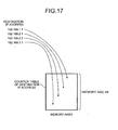
- Fig. 17 is a diagram explaining the calculation amount when the amount of traffics is calculated using a conventional communication system.
- a memory having a size of N which is predetermined for holding a counter table, is saved in the destination IP address counting units C1 to C4, respectively.
- the counter tables 101 to 104 are arranged on the saved memories, respectively.
- the memory area saved within the abnormal traffic analyzing unit 20 is divided into four as many as the number of the ISPs and each memory area stores each of the counter tables 101 to 104 therein.
- a list with the destination IP address as an index is stored in the memories (the counter tables 101 to 104) provided in the destination IP address counting units C1 to C4, respectively.
- each of the counter tables 101 to 104 holds an index and its counter value
- the calculation amounts for index retrieval are compared as one example of calculating the traffic amount.
- the calculation amount for index retrieval is calculated for the memory area holding the index, and the calculation amount for the memory area storing the counter value therein is not considered.
- the traffic separating unit 21 judges the counter table to be retrieved, at first.
- An expected value of the number of times for comparison (the number of times of calculation) of the destination IP addresses, which is necessary for judging the counter table to be retrieved, is 2. Therefore, when m (m is a natural number) samples of the IP packet have been received, the expected value of the number of times of comparison is 2m.
- the traffic separating unit 21 retrieves the destination IP address from the memory (index) having the size of N.
- the expected value of the number of times for comparison is N/2. From the above, the expected value of the number of times of comparison when m samples of the IP packet have been received is 2m+Nm/2.
- one counter table is arranged in a previously-saved memory.
- the layer 2 switch 11 receives the sFlow packet containing a predetermined destination IP address, the destination IP address is retrieved from the index having the size of 4N.
- the memory area having a total memory size of 4N is saved within the communication system (apparatus for analyzing an abnormal traffic).
- the expected value of the number of times for comparison is 2N.
- the expected value of the number of times of comparison is 2Nm.
- the comparison process is required (pNm/2) times in the conventional communication system (communication system having no traffic separating unit 21).
- the number of times for the comparison process is ((p+N)m/2).
- the abnormal traffic detection system 200 comprises one layer 2 switch 11, but a plural of the layer 2 switches 11 may be arranged in the abnormal traffic detection system 200 depending on the scale of the IX.
- the abnormal traffic detection system 200 comprises four ISPs 1 to 4, but the abnormal traffic detection system 200 may include three or less ISPs, or five or more ISPs.
- the layer 2 switch 11 may be connected to other communication apparatus such as an IDC (Internet data center) or a personal computer.
- IDC Internet data center
- the sFlow packet is used to detect an abnormal traffic in the present embodiment, a packet other than the sFlow packet may be used to detect an abnormal traffic, if the sFlow packet contains information on the traffics flowing through the layer 2 switch 11.
- the abnormal traffic analyzing unit 20 has the abnormal traffic judging units J1 to J4 as many as the destination IP address counting units C1 to C4, but three or less abnormal traffic judging units may be employed. In this case, one abnormal traffic judging unit detects an abnormal traffic for plural destination IP address counting units.
- the traffic information transmitting unit 30 of the abnormal traffic detection apparatus 100 monitors the traffics flowing through the layer 2 switch 11 and transmits the sFlow packet to the abnormal traffic analyzing unit 20, but the layer 2 switch 11 may directly transmit the sFlow packet to the abnormal traffic analyzing unit 20.
- the abnormal traffic detection apparatus 100 does not need to comprise the traffic information transmitting unit 30.
- the layer 2 switch 11 and the abnormal traffic analyzing unit 20 are connected to each other.
- the "destination MAC address" and the “destination VLAN” are associated with the "destination IP address” in the sFlow packet and the "destination MAC address” and the “destination VLAN” are associated with the ISP in the IX management information.
- the ISP which is to be routed at first to reach the destination IP address can be easily identified.
- the ISP where an abnormal traffic has occurred can be easily identified. Thus, it is possible to easily notify the ISP where the abnormal traffic has occurred of the fact that the abnormal traffic has occurred.
- the distribution range (storage area) of the destination IP addresses (traffics) to be stored becomes narrower. Therefore, since the number of indexes to be retrieved is reduced, a processing load for performing the destination IP address retrieval process is more reduced than the conventional retrieval method. Thus, abnormal traffics can be efficiently and rapidly detected in a simple structure.
- each element in each apparatus illustrated in the figures is functionally conceptual and does not necessarily be configured physically the same as indicated in the figures.
- specific forms of distribution and integration of the respective apparatuses are not limited to illustrated ones and all or part of them may be configured in a functionally or physically distributed or integrated manner in arbitrary unit depending on various loads or usage.
- all or part of each processing function performed in each apparatus can be obtained in a CPU and a program, which is analyzed and executed in the CPU, or can be obtained in a hardware, which is formed by using wired logic.
- the abnormal traffic detection apparatus 100 described in the first embodiment can be integrated in the layer 2 switch 11.
- the abnormal traffic detection method described in the first embodiment can be performed by executing a previously-prepared program in a computer such as personal computer or work station.
- the program can be distributed via a network such as Internet. Further, the program can be recorded in a computer readable recording medium such as hard disk, flexible disk (FD), CD-ROM, MO and DVD and can be read out from the recording medium by the computer for execution.
- a computer readable recording medium such as hard disk, flexible disk (FD), CD-ROM, MO and DVD
- the abnormal traffic detection apparatus, the abnormal traffic detection method, and the abnormal traffic detection program according to the present invention are suitable for detecting an abnormal traffic at an IX.
Landscapes
- Engineering & Computer Science (AREA)
- Computer Security & Cryptography (AREA)
- Computer Networks & Wireless Communication (AREA)
- Signal Processing (AREA)
- Computer Hardware Design (AREA)
- Computing Systems (AREA)
- General Engineering & Computer Science (AREA)
- Data Exchanges In Wide-Area Networks (AREA)
Claims (9)
- Appareil (100) de détection de trafic anormal qui, lorsque des trafics sont transmis et reçus entre des appareils de communication (1, 2, 3, 4) connectés à l'Internet par l'intermédiaire d'un commutateur (11), surveille les trafics passant à travers le commutateur (11) et utilise des informations de trafic sur les trafics surveillés pour détecter des trafics anormaux vers les appareils de communication (1, 2, 3, 4), comprenant:une unité (21) de séparation de trafic configurée pour identifier un appareil de communication (1, 2, 3, 4) comme étant la destination des trafics, et une adresse IP de destination des trafics sur la base des informations de trafic ;caractérisé parune pluralité d'unités (C1, C2, C3, C4) de stockage d'informations de quantité connectées à l'unité (21) de séparation de trafic, où chaque unité (C1, C2, C3, C4) de stockage d'informations de quantité correspond à un appareil de communication (1, 2, 3, 4) qui est une destination des trafics et est configurée pour :stocker des informations de quantité sur une quantité de trafic en tant que tableau (101, 102, 103, 104) d'informations de quantité, les informations de quantité étant incluses dans les informations de trafic, où chaque unité (C1, C2, C3, C4) de stockage d'informations de quantité est en outre configurée pour, lorsque l'appareil de communication identifié est l'appareil de communication correspondant (1, 2, 3, 4),enregistrer, lorsque l'adresse IP de destination identifiée est une nouvelle adresse IP de destination qui n'est pas stockée dans le tableau (101, 102, 103, 104) d'informations de quantité, la nouvelle adresse IP de destination dans le tableau (101, 102, 103, 104) d'informations de quantité et stocker ensuite les informations de quantité dans le tableau d'informations de quantité, qui correspond à l'appareil de communication identifié (1, 2, 3, 4) connecté au commutateur,stocker, lorsque l'adresse IP de destination identifiée est une adresse IP de destination déjà stockée dans le tableau (101, 102, 103, 104) d'informations de quantité, les informations de quantité dans le tableau (101, 102, 103, 104) d'informations de quantité, qui correspond à l'appareil de communication identifié (1, 2, 3, 4) connecté au commutateur ; etune pluralité d'unités (J1, J2, J3, J4) de jugement de trafic anormal, chaque unité (J1, J2, J3, J4) de jugement de trafic anormal étant connectée à l'une des unités (C1, C2, C3, C4) de stockage d'informations de quantité et étant configurée pour juger si la quantité de trafic passant à travers le commutateur (11) est anormale sur la base des informations de quantité stockées dans le tableau (101, 102, 103, 104) d'informations de quantité correspondant.
- Appareil (100) de détection de trafic anormal selon la revendication 1, dans lequel l'unité (21) de séparation de trafic est configurée pour identifier l'appareil de communication (ISP) comme étant la destination des trafics sur la base d'une adresse MAC de destination et d'un réseau VLAN de destination, les deux étant inclus dans les informations de trafic, et des informations préalablement stockées sur un appareil de communication correspondant à l'adresse MAC de destination et au réseau VLAN de destination.
- Appareil (100) de détection de trafic anormal selon la revendication 1 à 2, dans lequel chaque unité (J1, J2, J3, J4) de jugement de trafic anormal est configurée pour stocker des valeurs seuil, qui sont utilisées pour juger si la quantité de trafic est anormale, pour le tableau (101, 102, 103, 104) d'informations de quantité respectif, et est configurée pour comparer, pour le tableau (101, 102, 103, 104) d'informations de quantité respectif, les informations de quantité stockées dans le tableau d'informations de quantité et la valeur seuil correspondant aux informations de quantité afin de juger si la quantité de trafic passant à travers le commutateur (11) est anormale.
- Procédé de détection de trafic anormal qui, lorsque des trafics sont transmis et reçus entre des appareils de communication (1, 2, 3, 4) connectés à l'Internet par l'intermédiaire d'un commutateur (11), surveille les trafics passant à travers le commutateur (11) et utilise des informations de trafic sur les trafics surveillés pour détecter des trafics anormaux vers les appareils de communication (1, 2, 3, 4), comprenant :une étape d'acquisition d'informations de trafic consistant à acquérir les informations de trafic ;une étape d'identification de destination consistant à identifier un appareil de communication (1, 2, 3, 4) en tant que destination des trafics, et une adresse IP de destination des trafics sur la base des informations de trafic ;caractérisé parune étape de stockage d'informations de quantité consistant à stocker des informations de quantité sur une quantité de trafic incluses dans les informations de trafic en tant que tableaux (101, 102, 103, 104) d'informations de quantité où chaque tableau d'informations de quantité correspond à un appareil de communication (1, 2, 3, 4) qui est une destination des trafics, ladite étape de stockage comprenant, lorsque l'adresse IP de destination identifiée est une nouvelle adresse IP de destination qui n'est pas stockée dans le tableau (101, 102, 103, 104) d'informations de quantité, le fait d'enregistrer la nouvelle adresse IP de destination dans le tableau (101, 102, 103, 104) d'informations de quantité et de stocker ensuite les informations de quantité dans le tableau (101, 102, 103, 104) d'informations de quantité, qui correspond à l'appareil de communication identifié (1, 2, 3, 4) connecté au commutateur, et,lorsque l'adresse IP de destination identifiée est une adresse IP de destination déjà mémorisée dans le tableau (101, 102, 103, 104) d'informations de quantité, le fait de stocker les informations de quantité dans le tableau (101, 102, 103, 104) d'informations de quantité, qui correspond à l'appareil de communication identifié (1, 2, 3, 4) connecté au commutateur ; etune étape de jugement de trafic anormal consistant à juger, pour chacun des appareils de communication (1, 2, 3, 4), si la quantité de trafic passant à travers le commutateur (11) est anormale sur la base des informations de quantité stockées dans le tableau (101, 102, 103, 104) d'informations de quantité.
- Procédé de détection de trafic anormal selon la revendication 4, dans lequel l'étape de stockage d'informations de quantité comporte l'identification de l'appareil de communication comme étant la destination des trafics sur la base d'une adresse MAC de destination et d'un réseau VLAN de destination, les deux étant inclus dans les informations de trafic, et des informations préalablement stockées sur un dispositif de communication correspondant à l'adresse MAC de destination et au réseau VLAN de destination.
- Procédé de détection de trafic anormal selon la revendication 4 à 5, dans lequel l'étape de jugement de trafic anormal comporte le stockage des valeurs seuil, qui sont utilisées pour juger si la quantité de trafic est anormale, pour les tableaux (101, 102, 103, 104) d'informations de quantité respectifs, et la comparaison, pour chacun des tableaux (101, 102, 103, 104) d'informations de quantité, des informations de quantité stockées dans le tableau (101, 102, 103, 104) d'informations de quantité et la valeur seuil correspondant aux informations de quantité afin de juger si la quantité de trafic passant à travers le commutateur (11) est anormale.
- Programme de détection de trafic anormal qui utilise des informations de trafic sur des trafics, qui sont surveillés au moment de la transmission et de la réception, passant à travers un commutateur (11) entre des appareils de communication (1, 2, 3, 4) connectés à l'Internet par l'intermédiaire du commutateur (11), pour amener un ordinateur à détecter des trafics anormaux vers les appareils de communication (1, 2, 3, 4), comprenant :une étape d'acquisition d'informations de trafic consistant à acquérir les informations de trafic ;une étape d'identification de destination consistant à identifier un appareil de communication (1, 2, 3, 4) en tant que destination des trafics, et une adresse IP de destination des trafics sur la base des informations de trafic ;caractérisé parune étape de stockage d'informations de quantité consistant à stocker des informations de quantité sur une quantité de trafic incluses dans les informations de trafic en tant que tableaux (101, 102, 103, 104) d'informations de quantité où chaque tableau d'informations de quantité correspond à un appareil de communication (1, 2, 3, 4) qui est une destination des trafics, ladite étape de stockage comprenant, lorsque l'adresse IP de destination identifiée est une nouvelle adresse IP de destination qui n'est pas stockée dans le tableau (101, 102, 103, 104) d'informations de quantité, le fait d'enregistrer la nouvelle adresse IP de destination dans le tableau (101, 102, 103, 104) d'informations de quantité et de stocker ensuite les informations de quantité dans le tableau (101, 102, 103, 104) d'informations de quantité, qui correspond à l'appareil de communication identifié (1, 2, 3, 4) connecté au commutateur, et,lorsque l'adresse IP de destination identifiée est une adresse IP de destination déjà mémorisée dans le tableau (101, 102, 103, 104) d'informations de quantité, le fait de stocker les informations de quantité dans le tableau (101, 102, 103, 104) d'informations de quantité, qui correspond à l'appareil de communication identifié (1, 2, 3, 4) connecté au commutateur ; etune étape de jugement de trafic anormal consistant à juger, pour chacun des appareils de communication (1, 2, 3, 4), si la quantité de trafic passant à travers le commutateur (11) est anormale sur la base des informations de quantité stockées dans le tableau (101, 102, 103, 104) d'informations de quantité.
- Programme de détection de trafic anormal selon la revendication 7, dans lequel l'étape de stockage d'informations de quantité comporte l'identification de l'appareil de communication comme étant la destination des trafics sur la base d'une adresse MAC de destination et d'un réseau VLAN de destination, les deux étant inclus dans les informations de trafic, et des informations préalablement stockées sur un dispositif de communication correspondant à l'adresse MAC de destination et au réseau VLAN de destination.
- Programme de détection de trafic anormal selon la revendication 7 à 8, dans lequel l'étape de jugement de trafic anormal comporte le stockage des valeurs seuil, qui sont utilisées pour juger si la quantité de trafic est anormale, pour les tableaux (101, 102, 103, 104) d'informations de quantité respectifs, et la comparaison, pour chacun des tableaux (101, 102, 103, 104) d'informations de quantité, des informations de quantité stockées dans le tableau (101, 102, 103, 104) d'informations de quantité et la valeur seuil correspondant aux informations de quantité afin de juger si la quantité de trafic passant à travers le commutateur (11) est anormale.
Applications Claiming Priority (2)
| Application Number | Priority Date | Filing Date | Title |
|---|---|---|---|
| JP2007258798A JP4667437B2 (ja) | 2007-10-02 | 2007-10-02 | 異常トラフィック検知装置、異常トラフィック検知方法および異常トラフィック検知プログラム |
| PCT/JP2008/067317 WO2009044660A1 (fr) | 2007-10-02 | 2008-09-25 | Dispositif de détection de trafic anormal, procédé de détection de trafic anormal et programme de détection de trafic anormal |
Publications (3)
| Publication Number | Publication Date |
|---|---|
| EP2187577A1 EP2187577A1 (fr) | 2010-05-19 |
| EP2187577A4 EP2187577A4 (fr) | 2011-07-20 |
| EP2187577B1 true EP2187577B1 (fr) | 2013-01-02 |
Family
ID=40526089
Family Applications (1)
| Application Number | Title | Priority Date | Filing Date |
|---|---|---|---|
| EP08834894A Not-in-force EP2187577B1 (fr) | 2007-10-02 | 2008-09-25 | Dispositif de détection de trafic anormal, procédé de détection de trafic anormal et programme de détection de trafic anormal |
Country Status (5)
| Country | Link |
|---|---|
| US (1) | US8422386B2 (fr) |
| EP (1) | EP2187577B1 (fr) |
| JP (1) | JP4667437B2 (fr) |
| CN (1) | CN101803312B (fr) |
| WO (1) | WO2009044660A1 (fr) |
Families Citing this family (43)
| Publication number | Priority date | Publication date | Assignee | Title |
|---|---|---|---|---|
| EP3401794A1 (fr) | 2002-01-08 | 2018-11-14 | Seven Networks, LLC | Architecture de connexion pour un réseau mobile |
| US8438633B1 (en) | 2005-04-21 | 2013-05-07 | Seven Networks, Inc. | Flexible real-time inbox access |
| WO2006136660A1 (fr) | 2005-06-21 | 2006-12-28 | Seven Networks International Oy | Maintien d'une connexion ip dans un reseau mobile |
| US8805425B2 (en) | 2007-06-01 | 2014-08-12 | Seven Networks, Inc. | Integrated messaging |
| JP4667437B2 (ja) | 2007-10-02 | 2011-04-13 | 日本電信電話株式会社 | 異常トラフィック検知装置、異常トラフィック検知方法および異常トラフィック検知プログラム |
| US9002828B2 (en) | 2007-12-13 | 2015-04-07 | Seven Networks, Inc. | Predictive content delivery |
| US8862657B2 (en) | 2008-01-25 | 2014-10-14 | Seven Networks, Inc. | Policy based content service |
| US20090193338A1 (en) | 2008-01-28 | 2009-07-30 | Trevor Fiatal | Reducing network and battery consumption during content delivery and playback |
| US8909759B2 (en) | 2008-10-10 | 2014-12-09 | Seven Networks, Inc. | Bandwidth measurement |
| US8838783B2 (en) | 2010-07-26 | 2014-09-16 | Seven Networks, Inc. | Distributed caching for resource and mobile network traffic management |
| GB2497012B (en) | 2010-07-26 | 2013-10-30 | Seven Networks Inc | Mobile network traffic coordination across multiple applications |
| US8775613B2 (en) | 2010-10-14 | 2014-07-08 | Electronics And Telecommunications Research Institute | Method and system for providing network monitoring, security event collection apparatus and service abnormality detection apparatus for network monitoring |
| WO2012060995A2 (fr) | 2010-11-01 | 2012-05-10 | Michael Luna | Mise en cache distribuée dans un réseau sans fil d'un contenu fourni par une application mobile sur une requête de longue durée |
| US8843153B2 (en) | 2010-11-01 | 2014-09-23 | Seven Networks, Inc. | Mobile traffic categorization and policy for network use optimization while preserving user experience |
| KR20120071123A (ko) * | 2010-12-22 | 2012-07-02 | 한국전자통신연구원 | 비정상 트래픽 감지 장치 및 방법 |
| GB2505103B (en) | 2011-04-19 | 2014-10-22 | Seven Networks Inc | Social caching for device resource sharing and management cross-reference to related applications |
| GB2493473B (en) | 2011-04-27 | 2013-06-19 | Seven Networks Inc | System and method for making requests on behalf of a mobile device based on atomic processes for mobile network traffic relief |
| CN102291411B (zh) * | 2011-08-18 | 2013-11-06 | 网宿科技股份有限公司 | 针对dns服务的防ddos攻击方法和系统 |
| EP2789138B1 (fr) | 2011-12-06 | 2016-09-14 | Seven Networks, LLC | Dispositif mobile et procédé pour utiliser les mécanismes de basculement pour une tolérance aux anomalies fournie pour une gestion de trafic mobile et une conservation de ressource de réseau/dispositif |
| US8934414B2 (en) | 2011-12-06 | 2015-01-13 | Seven Networks, Inc. | Cellular or WiFi mobile traffic optimization based on public or private network destination |
| WO2013086447A1 (fr) | 2011-12-07 | 2013-06-13 | Seven Networks, Inc. | Sensibilité radio d'un dispositif mobile pour envoyer des signaux de commande côté serveur au moyen d'un protocole de transport optimisé de réseau sans fil |
| WO2013086455A1 (fr) | 2011-12-07 | 2013-06-13 | Seven Networks, Inc. | Schémas d'intégration flexibles et dynamiques d'un système de gestion de trafic avec divers opérateurs de réseau permettant d'alléger le trafic du réseau |
| WO2013090212A1 (fr) | 2011-12-14 | 2013-06-20 | Seven Networks, Inc. | Système et procédé de rapport et d'analyse d'utilisation de réseau mobile utilisant une agrégation de données dans un système d'optimisation de trafic distribué |
| US8812695B2 (en) | 2012-04-09 | 2014-08-19 | Seven Networks, Inc. | Method and system for management of a virtual network connection without heartbeat messages |
| US20130316675A1 (en) * | 2012-05-24 | 2013-11-28 | Seven Networks, Inc. | Facilitation of mobile operator billing based on wireless network traffic management and tracking of destination address in conjunction with billing policies |
| US8775631B2 (en) | 2012-07-13 | 2014-07-08 | Seven Networks, Inc. | Dynamic bandwidth adjustment for browsing or streaming activity in a wireless network based on prediction of user behavior when interacting with mobile applications |
| JP5958354B2 (ja) * | 2013-01-16 | 2016-07-27 | 富士通株式会社 | 通信監視装置、発生予測方法及び発生予測プログラム |
| US8874761B2 (en) | 2013-01-25 | 2014-10-28 | Seven Networks, Inc. | Signaling optimization in a wireless network for traffic utilizing proprietary and non-proprietary protocols |
| US9326185B2 (en) | 2013-03-11 | 2016-04-26 | Seven Networks, Llc | Mobile network congestion recognition for optimization of mobile traffic |
| US9065765B2 (en) | 2013-07-22 | 2015-06-23 | Seven Networks, Inc. | Proxy server associated with a mobile carrier for enhancing mobile traffic management in a mobile network |
| US9774566B2 (en) * | 2013-11-29 | 2017-09-26 | Acer Incorporated | Communication method and mobile electronic device using the same |
| KR102045468B1 (ko) * | 2015-07-27 | 2019-11-15 | 한국전자통신연구원 | 네트워크 데이터 분석에 기반한 비정상 연결 행위 탐지 장치 및 방법 |
| CN105306436B (zh) | 2015-09-16 | 2016-08-24 | 广东睿江云计算股份有限公司 | 一种异常流量检测方法 |
| US10021130B2 (en) * | 2015-09-28 | 2018-07-10 | Verizon Patent And Licensing Inc. | Network state information correlation to detect anomalous conditions |
| CN106027559B (zh) * | 2016-07-05 | 2019-07-05 | 国家计算机网络与信息安全管理中心 | 基于网络会话统计特征的大规模网络扫描检测方法 |
| JP6612197B2 (ja) * | 2016-08-22 | 2019-11-27 | 日本電信電話株式会社 | DDoS連携対処装置、DDoS連携対処方法及びプログラム |
| JP6793524B2 (ja) * | 2016-11-01 | 2020-12-02 | 株式会社日立製作所 | ログ解析システムおよびその方法 |
| JP6760185B2 (ja) * | 2017-03-31 | 2020-09-23 | 住友電気工業株式会社 | 中継装置、検知方法および検知プログラム |
| EP3422659A1 (fr) * | 2017-06-30 | 2019-01-02 | Thomson Licensing | Procédé de blocage des attaques par déni de service distribué et appareil correspondant |
| US11750622B1 (en) | 2017-09-05 | 2023-09-05 | Barefoot Networks, Inc. | Forwarding element with a data plane DDoS attack detector |
| US11108812B1 (en) | 2018-04-16 | 2021-08-31 | Barefoot Networks, Inc. | Data plane with connection validation circuits |
| JP6927155B2 (ja) * | 2018-05-30 | 2021-08-25 | 日本電信電話株式会社 | 異常検出装置、異常検出方法および異常検出プログラム |
| CN112583850B (zh) * | 2020-12-27 | 2023-02-24 | 杭州迪普科技股份有限公司 | 网络攻击防护方法、装置及系统 |
Family Cites Families (11)
| Publication number | Priority date | Publication date | Assignee | Title |
|---|---|---|---|---|
| US6298123B1 (en) * | 1998-03-26 | 2001-10-02 | Bell Atlantic Network Services, Inc. | Interconnect traffic tracking |
| US6954462B1 (en) * | 2000-07-31 | 2005-10-11 | Cisco Technology, Inc. | Method and apparatus for determining a multilayer switching path |
| JP3657569B2 (ja) | 2002-03-20 | 2005-06-08 | 日本電信電話株式会社 | パケット処理方法および通信装置 |
| JP3949610B2 (ja) * | 2003-05-28 | 2007-07-25 | 日本電信電話株式会社 | 攻撃パケット対策システム及び攻撃パケット対策方法 |
| JP2005057408A (ja) * | 2003-08-01 | 2005-03-03 | Nippon Telegr & Teleph Corp <Ntt> | Upc装置 |
| JP4480422B2 (ja) | 2004-03-05 | 2010-06-16 | 富士通株式会社 | 不正アクセス阻止方法、装置及びシステム並びにプログラム |
| JP4512196B2 (ja) * | 2005-10-20 | 2010-07-28 | アラクサラネットワークス株式会社 | 異常トラヒックの検出方法およびパケット中継装置 |
| US9794272B2 (en) * | 2006-01-03 | 2017-10-17 | Alcatel Lucent | Method and apparatus for monitoring malicious traffic in communication networks |
| JP4126707B2 (ja) * | 2006-07-28 | 2008-07-30 | インターナショナル・ビジネス・マシーンズ・コーポレーション | 情報システムの状態を解析する技術 |
| JP4871775B2 (ja) * | 2007-04-06 | 2012-02-08 | アラクサラネットワークス株式会社 | 統計情報収集装置 |
| JP4667437B2 (ja) | 2007-10-02 | 2011-04-13 | 日本電信電話株式会社 | 異常トラフィック検知装置、異常トラフィック検知方法および異常トラフィック検知プログラム |
-
2007
- 2007-10-02 JP JP2007258798A patent/JP4667437B2/ja active Active
-
2008
- 2008-09-25 WO PCT/JP2008/067317 patent/WO2009044660A1/fr not_active Ceased
- 2008-09-25 CN CN2008801079028A patent/CN101803312B/zh not_active Expired - Fee Related
- 2008-09-25 US US12/679,029 patent/US8422386B2/en active Active
- 2008-09-25 EP EP08834894A patent/EP2187577B1/fr not_active Not-in-force
Also Published As
| Publication number | Publication date |
|---|---|
| EP2187577A4 (fr) | 2011-07-20 |
| CN101803312A (zh) | 2010-08-11 |
| US20100220619A1 (en) | 2010-09-02 |
| EP2187577A1 (fr) | 2010-05-19 |
| JP4667437B2 (ja) | 2011-04-13 |
| HK1142200A1 (en) | 2010-11-26 |
| CN101803312B (zh) | 2013-08-14 |
| JP2009089241A (ja) | 2009-04-23 |
| WO2009044660A1 (fr) | 2009-04-09 |
| US8422386B2 (en) | 2013-04-16 |
Similar Documents
| Publication | Publication Date | Title |
|---|---|---|
| US8422386B2 (en) | Abnormal traffic detection apparatus, abnormal traffic detection method and abnormal traffic detection program | |
| US7729271B2 (en) | Detection method for abnormal traffic and packet relay apparatus | |
| US8627477B2 (en) | Method, apparatus, and system for detecting a zombie host | |
| JP4556981B2 (ja) | ネットワーク監視装置及びネットワーク監視方法 | |
| US9444821B2 (en) | Management server, communication cutoff device and information processing system | |
| US20090180393A1 (en) | Sampling apparatus distinguishing a failure in a network even by using a single sampling and a method therefor | |
| JP5015014B2 (ja) | トラヒック分析診断装置及びトラヒック分析診断システム並びにトラヒック追跡システム | |
| US20060198313A1 (en) | Method and device for detecting and blocking unauthorized access | |
| JP2006352831A (ja) | ネットワーク制御装置およびその制御方法 | |
| JP4412031B2 (ja) | ネットワーク監視システム及びその方法、プログラム | |
| KR20140088340A (ko) | 오픈플로우 스위치에서의 디도스 공격 처리 장치 및 방법 | |
| JP2010088031A (ja) | アンダーレイネットワーク障害検知方法及びネットワークシステム | |
| US11895146B2 (en) | Infection-spreading attack detection system and method, and program | |
| CN100479396C (zh) | 一种检测报文攻击的方法及装置 | |
| JP4985435B2 (ja) | 監視分析装置、方法、及び、プログラム | |
| KR101469285B1 (ko) | 정책기반 라우팅을 이용한 선택적인 인터넷 트래픽 분석 시스템 및 그 방법 | |
| JP4246238B2 (ja) | トラフィック情報の配信及び収集方法 | |
| US8593974B2 (en) | Communication conditions determination method, communication conditions determination system, and determination apparatus | |
| JP5180247B2 (ja) | パケットサンプリング装置と方法およびプログラム | |
| JP2004164107A (ja) | 不正アクセス監視システム | |
| HK1142200B (en) | Abnormal traffic detection device, abnormal traffic detection method, and abnormal traffic detection program | |
| CN115766155B (zh) | 一种DDoS攻击防御方法及设备 | |
| JP4244355B2 (ja) | 通過パケット監視装置および方法 | |
| JP4028532B2 (ja) | 通信ネットワークトラヒック分析装置、システム、および分析方法 | |
| JP2013255196A (ja) | ネットワーク監視装置及びネットワーク監視方法 |
Legal Events
| Date | Code | Title | Description |
|---|---|---|---|
| PUAI | Public reference made under article 153(3) epc to a published international application that has entered the european phase |
Free format text: ORIGINAL CODE: 0009012 |
|
| 17P | Request for examination filed |
Effective date: 20100318 |
|
| AK | Designated contracting states |
Kind code of ref document: A1 Designated state(s): AT BE BG CH CY CZ DE DK EE ES FI FR GB GR HR HU IE IS IT LI LT LU LV MC MT NL NO PL PT RO SE SI SK TR |
|
| AX | Request for extension of the european patent |
Extension state: AL BA MK RS |
|
| REG | Reference to a national code |
Ref country code: HK Ref legal event code: DE Ref document number: 1142200 Country of ref document: HK |
|
| DAX | Request for extension of the european patent (deleted) | ||
| REG | Reference to a national code |
Ref country code: DE Ref legal event code: R079 Ref document number: 602008021426 Country of ref document: DE Free format text: PREVIOUS MAIN CLASS: H04L0012560000 Ipc: H04L0012260000 |
|
| RIC1 | Information provided on ipc code assigned before grant |
Ipc: H04L 29/06 20060101ALI20110523BHEP Ipc: H04L 12/26 20060101AFI20110523BHEP |
|
| A4 | Supplementary search report drawn up and despatched |
Effective date: 20110620 |
|
| GRAP | Despatch of communication of intention to grant a patent |
Free format text: ORIGINAL CODE: EPIDOSNIGR1 |
|
| GRAS | Grant fee paid |
Free format text: ORIGINAL CODE: EPIDOSNIGR3 |
|
| GRAP | Despatch of communication of intention to grant a patent |
Free format text: ORIGINAL CODE: EPIDOSNIGR1 |
|
| GRAA | (expected) grant |
Free format text: ORIGINAL CODE: 0009210 |
|
| AK | Designated contracting states |
Kind code of ref document: B1 Designated state(s): AT BE BG CH CY CZ DE DK EE ES FI FR GB GR HR HU IE IS IT LI LT LU LV MC MT NL NO PL PT RO SE SI SK TR |
|
| REG | Reference to a national code |
Ref country code: GB Ref legal event code: FG4D |
|
| REG | Reference to a national code |
Ref country code: AT Ref legal event code: REF Ref document number: 592116 Country of ref document: AT Kind code of ref document: T Effective date: 20130115 Ref country code: CH Ref legal event code: EP |
|
| REG | Reference to a national code |
Ref country code: IE Ref legal event code: FG4D |
|
| REG | Reference to a national code |
Ref country code: DE Ref legal event code: R096 Ref document number: 602008021426 Country of ref document: DE Effective date: 20130228 |
|
| REG | Reference to a national code |
Ref country code: AT Ref legal event code: MK05 Ref document number: 592116 Country of ref document: AT Kind code of ref document: T Effective date: 20130102 |
|
| REG | Reference to a national code |
Ref country code: NL Ref legal event code: VDEP Effective date: 20130102 |
|
| PG25 | Lapsed in a contracting state [announced via postgrant information from national office to epo] |
Ref country code: SI Free format text: LAPSE BECAUSE OF FAILURE TO SUBMIT A TRANSLATION OF THE DESCRIPTION OR TO PAY THE FEE WITHIN THE PRESCRIBED TIME-LIMIT Effective date: 20130102 |
|
| REG | Reference to a national code |
Ref country code: HK Ref legal event code: GR Ref document number: 1142200 Country of ref document: HK |
|
| REG | Reference to a national code |
Ref country code: LT Ref legal event code: MG4D |
|
| PG25 | Lapsed in a contracting state [announced via postgrant information from national office to epo] |
Ref country code: NO Free format text: LAPSE BECAUSE OF FAILURE TO SUBMIT A TRANSLATION OF THE DESCRIPTION OR TO PAY THE FEE WITHIN THE PRESCRIBED TIME-LIMIT Effective date: 20130402 Ref country code: SE Free format text: LAPSE BECAUSE OF FAILURE TO SUBMIT A TRANSLATION OF THE DESCRIPTION OR TO PAY THE FEE WITHIN THE PRESCRIBED TIME-LIMIT Effective date: 20130102 Ref country code: LT Free format text: LAPSE BECAUSE OF FAILURE TO SUBMIT A TRANSLATION OF THE DESCRIPTION OR TO PAY THE FEE WITHIN THE PRESCRIBED TIME-LIMIT Effective date: 20130102 Ref country code: BG Free format text: LAPSE BECAUSE OF FAILURE TO SUBMIT A TRANSLATION OF THE DESCRIPTION OR TO PAY THE FEE WITHIN THE PRESCRIBED TIME-LIMIT Effective date: 20130402 Ref country code: IS Free format text: LAPSE BECAUSE OF FAILURE TO SUBMIT A TRANSLATION OF THE DESCRIPTION OR TO PAY THE FEE WITHIN THE PRESCRIBED TIME-LIMIT Effective date: 20130502 Ref country code: CZ Free format text: LAPSE BECAUSE OF FAILURE TO SUBMIT A TRANSLATION OF THE DESCRIPTION OR TO PAY THE FEE WITHIN THE PRESCRIBED TIME-LIMIT Effective date: 20130102 Ref country code: ES Free format text: LAPSE BECAUSE OF FAILURE TO SUBMIT A TRANSLATION OF THE DESCRIPTION OR TO PAY THE FEE WITHIN THE PRESCRIBED TIME-LIMIT Effective date: 20130413 Ref country code: AT Free format text: LAPSE BECAUSE OF FAILURE TO SUBMIT A TRANSLATION OF THE DESCRIPTION OR TO PAY THE FEE WITHIN THE PRESCRIBED TIME-LIMIT Effective date: 20130102 Ref country code: BE Free format text: LAPSE BECAUSE OF FAILURE TO SUBMIT A TRANSLATION OF THE DESCRIPTION OR TO PAY THE FEE WITHIN THE PRESCRIBED TIME-LIMIT Effective date: 20130102 |
|
| PG25 | Lapsed in a contracting state [announced via postgrant information from national office to epo] |
Ref country code: PL Free format text: LAPSE BECAUSE OF FAILURE TO SUBMIT A TRANSLATION OF THE DESCRIPTION OR TO PAY THE FEE WITHIN THE PRESCRIBED TIME-LIMIT Effective date: 20130102 Ref country code: FI Free format text: LAPSE BECAUSE OF FAILURE TO SUBMIT A TRANSLATION OF THE DESCRIPTION OR TO PAY THE FEE WITHIN THE PRESCRIBED TIME-LIMIT Effective date: 20130102 Ref country code: NL Free format text: LAPSE BECAUSE OF FAILURE TO SUBMIT A TRANSLATION OF THE DESCRIPTION OR TO PAY THE FEE WITHIN THE PRESCRIBED TIME-LIMIT Effective date: 20130102 Ref country code: PT Free format text: LAPSE BECAUSE OF FAILURE TO SUBMIT A TRANSLATION OF THE DESCRIPTION OR TO PAY THE FEE WITHIN THE PRESCRIBED TIME-LIMIT Effective date: 20130502 Ref country code: GR Free format text: LAPSE BECAUSE OF FAILURE TO SUBMIT A TRANSLATION OF THE DESCRIPTION OR TO PAY THE FEE WITHIN THE PRESCRIBED TIME-LIMIT Effective date: 20130403 Ref country code: LV Free format text: LAPSE BECAUSE OF FAILURE TO SUBMIT A TRANSLATION OF THE DESCRIPTION OR TO PAY THE FEE WITHIN THE PRESCRIBED TIME-LIMIT Effective date: 20130102 |
|
| PG25 | Lapsed in a contracting state [announced via postgrant information from national office to epo] |
Ref country code: HR Free format text: LAPSE BECAUSE OF FAILURE TO SUBMIT A TRANSLATION OF THE DESCRIPTION OR TO PAY THE FEE WITHIN THE PRESCRIBED TIME-LIMIT Effective date: 20130102 |
|
| PG25 | Lapsed in a contracting state [announced via postgrant information from national office to epo] |
Ref country code: RO Free format text: LAPSE BECAUSE OF FAILURE TO SUBMIT A TRANSLATION OF THE DESCRIPTION OR TO PAY THE FEE WITHIN THE PRESCRIBED TIME-LIMIT Effective date: 20130102 Ref country code: DK Free format text: LAPSE BECAUSE OF FAILURE TO SUBMIT A TRANSLATION OF THE DESCRIPTION OR TO PAY THE FEE WITHIN THE PRESCRIBED TIME-LIMIT Effective date: 20130102 Ref country code: SK Free format text: LAPSE BECAUSE OF FAILURE TO SUBMIT A TRANSLATION OF THE DESCRIPTION OR TO PAY THE FEE WITHIN THE PRESCRIBED TIME-LIMIT Effective date: 20130102 Ref country code: EE Free format text: LAPSE BECAUSE OF FAILURE TO SUBMIT A TRANSLATION OF THE DESCRIPTION OR TO PAY THE FEE WITHIN THE PRESCRIBED TIME-LIMIT Effective date: 20130102 |
|
| PLBE | No opposition filed within time limit |
Free format text: ORIGINAL CODE: 0009261 |
|
| STAA | Information on the status of an ep patent application or granted ep patent |
Free format text: STATUS: NO OPPOSITION FILED WITHIN TIME LIMIT |
|
| PG25 | Lapsed in a contracting state [announced via postgrant information from national office to epo] |
Ref country code: CY Free format text: LAPSE BECAUSE OF FAILURE TO SUBMIT A TRANSLATION OF THE DESCRIPTION OR TO PAY THE FEE WITHIN THE PRESCRIBED TIME-LIMIT Effective date: 20130102 |
|
| 26N | No opposition filed |
Effective date: 20131003 |
|
| PG25 | Lapsed in a contracting state [announced via postgrant information from national office to epo] |
Ref country code: IT Free format text: LAPSE BECAUSE OF FAILURE TO SUBMIT A TRANSLATION OF THE DESCRIPTION OR TO PAY THE FEE WITHIN THE PRESCRIBED TIME-LIMIT Effective date: 20130102 |
|
| REG | Reference to a national code |
Ref country code: DE Ref legal event code: R097 Ref document number: 602008021426 Country of ref document: DE Effective date: 20131003 |
|
| PG25 | Lapsed in a contracting state [announced via postgrant information from national office to epo] |
Ref country code: MC Free format text: LAPSE BECAUSE OF FAILURE TO SUBMIT A TRANSLATION OF THE DESCRIPTION OR TO PAY THE FEE WITHIN THE PRESCRIBED TIME-LIMIT Effective date: 20130102 |
|
| REG | Reference to a national code |
Ref country code: CH Ref legal event code: PL |
|
| REG | Reference to a national code |
Ref country code: IE Ref legal event code: MM4A |
|
| PG25 | Lapsed in a contracting state [announced via postgrant information from national office to epo] |
Ref country code: LI Free format text: LAPSE BECAUSE OF NON-PAYMENT OF DUE FEES Effective date: 20130930 Ref country code: IE Free format text: LAPSE BECAUSE OF NON-PAYMENT OF DUE FEES Effective date: 20130925 Ref country code: CH Free format text: LAPSE BECAUSE OF NON-PAYMENT OF DUE FEES Effective date: 20130930 |
|
| PG25 | Lapsed in a contracting state [announced via postgrant information from national office to epo] |
Ref country code: MT Free format text: LAPSE BECAUSE OF FAILURE TO SUBMIT A TRANSLATION OF THE DESCRIPTION OR TO PAY THE FEE WITHIN THE PRESCRIBED TIME-LIMIT Effective date: 20130102 Ref country code: TR Free format text: LAPSE BECAUSE OF FAILURE TO SUBMIT A TRANSLATION OF THE DESCRIPTION OR TO PAY THE FEE WITHIN THE PRESCRIBED TIME-LIMIT Effective date: 20130102 |
|
| PG25 | Lapsed in a contracting state [announced via postgrant information from national office to epo] |
Ref country code: LU Free format text: LAPSE BECAUSE OF NON-PAYMENT OF DUE FEES Effective date: 20130925 Ref country code: HU Free format text: LAPSE BECAUSE OF FAILURE TO SUBMIT A TRANSLATION OF THE DESCRIPTION OR TO PAY THE FEE WITHIN THE PRESCRIBED TIME-LIMIT; INVALID AB INITIO Effective date: 20080925 |
|
| REG | Reference to a national code |
Ref country code: FR Ref legal event code: PLFP Year of fee payment: 9 |
|
| REG | Reference to a national code |
Ref country code: FR Ref legal event code: PLFP Year of fee payment: 10 |
|
| REG | Reference to a national code |
Ref country code: FR Ref legal event code: PLFP Year of fee payment: 11 |
|
| PGFP | Annual fee paid to national office [announced via postgrant information from national office to epo] |
Ref country code: FR Payment date: 20180925 Year of fee payment: 11 Ref country code: DE Payment date: 20180920 Year of fee payment: 11 |
|
| PGFP | Annual fee paid to national office [announced via postgrant information from national office to epo] |
Ref country code: GB Payment date: 20180919 Year of fee payment: 11 |
|
| REG | Reference to a national code |
Ref country code: DE Ref legal event code: R119 Ref document number: 602008021426 Country of ref document: DE |
|
| PG25 | Lapsed in a contracting state [announced via postgrant information from national office to epo] |
Ref country code: DE Free format text: LAPSE BECAUSE OF NON-PAYMENT OF DUE FEES Effective date: 20200401 |
|
| GBPC | Gb: european patent ceased through non-payment of renewal fee |
Effective date: 20190925 |
|
| PG25 | Lapsed in a contracting state [announced via postgrant information from national office to epo] |
Ref country code: FR Free format text: LAPSE BECAUSE OF NON-PAYMENT OF DUE FEES Effective date: 20190930 Ref country code: GB Free format text: LAPSE BECAUSE OF NON-PAYMENT OF DUE FEES Effective date: 20190925 |