EP2187617A1 - Dispositif d'enregistrement de données d'images assistées par corps volant à partir de la surface de corps célestes - Google Patents
Dispositif d'enregistrement de données d'images assistées par corps volant à partir de la surface de corps célestes Download PDFInfo
- Publication number
- EP2187617A1 EP2187617A1 EP09176181A EP09176181A EP2187617A1 EP 2187617 A1 EP2187617 A1 EP 2187617A1 EP 09176181 A EP09176181 A EP 09176181A EP 09176181 A EP09176181 A EP 09176181A EP 2187617 A1 EP2187617 A1 EP 2187617A1
- Authority
- EP
- European Patent Office
- Prior art keywords
- sensor arrays
- cameras
- field
- sensor
- view
- Prior art date
- Legal status (The legal status is an assumption and is not a legal conclusion. Google has not performed a legal analysis and makes no representation as to the accuracy of the status listed.)
- Withdrawn
Links
- 238000003491 array Methods 0.000 claims abstract description 73
- 230000003287 optical effect Effects 0.000 claims abstract description 43
- 230000000007 visual effect Effects 0.000 claims abstract description 9
- 238000003384 imaging method Methods 0.000 claims description 8
- 230000001419 dependent effect Effects 0.000 claims description 4
- 238000013461 design Methods 0.000 description 5
- 238000000034 method Methods 0.000 description 4
- 230000010287 polarization Effects 0.000 description 4
- 229920013655 poly(bisphenol-A sulfone) Polymers 0.000 description 4
- 230000000295 complement effect Effects 0.000 description 3
- 230000003595 spectral effect Effects 0.000 description 3
- 238000003702 image correction Methods 0.000 description 2
- 238000013507 mapping Methods 0.000 description 2
- 238000005259 measurement Methods 0.000 description 2
- 238000012634 optical imaging Methods 0.000 description 2
- 238000012545 processing Methods 0.000 description 2
- 238000002310 reflectometry Methods 0.000 description 2
- 238000005070 sampling Methods 0.000 description 2
- 229910000679 solder Inorganic materials 0.000 description 2
- 241001420622 Meris Species 0.000 description 1
- 230000004075 alteration Effects 0.000 description 1
- 238000013459 approach Methods 0.000 description 1
- 238000012937 correction Methods 0.000 description 1
- 238000001514 detection method Methods 0.000 description 1
- 238000011161 development Methods 0.000 description 1
- 230000000694 effects Effects 0.000 description 1
- 239000011159 matrix material Substances 0.000 description 1
- 238000001454 recorded image Methods 0.000 description 1
- 230000002123 temporal effect Effects 0.000 description 1
- 238000010200 validation analysis Methods 0.000 description 1
Images


Classifications
-
- G—PHYSICS
- G01—MEASURING; TESTING
- G01C—MEASURING DISTANCES, LEVELS OR BEARINGS; SURVEYING; NAVIGATION; GYROSCOPIC INSTRUMENTS; PHOTOGRAMMETRY OR VIDEOGRAMMETRY
- G01C11/00—Photogrammetry or videogrammetry, e.g. stereogrammetry; Photographic surveying
- G01C11/02—Picture taking arrangements specially adapted for photogrammetry or photographic surveying, e.g. controlling overlapping of pictures
- G01C11/025—Picture taking arrangements specially adapted for photogrammetry or photographic surveying, e.g. controlling overlapping of pictures by scanning the object
-
- H—ELECTRICITY
- H04—ELECTRIC COMMUNICATION TECHNIQUE
- H04N—PICTORIAL COMMUNICATION, e.g. TELEVISION
- H04N25/00—Circuitry of solid-state image sensors [SSIS]; Control thereof
- H04N25/40—Extracting pixel data from image sensors by controlling scanning circuits, e.g. by modifying the number of pixels sampled or to be sampled
- H04N25/41—Extracting pixel data from a plurality of image sensors simultaneously picking up an image, e.g. for increasing the field of view by combining the outputs of a plurality of sensors
Definitions
- the invention relates to an arrangement for missile-based image data recording of the surface of a celestial body, in which an optically imaging instrument has a plurality of sensor arrays in order to increase the field of view of the image recording in the flight direction or transversely thereto while maintaining the required resolution for each flyover It finds predominantly application for facilitating the co-registration of multi-channel (eg spectrally or polarization optically different) recorded image data from the surface of a celestial body, in particular the earth.
- multi-channel eg spectrally or polarization optically different
- swathing is introduced and understood that in addition to the conventionally used term of swath width as the width of the Abtastspur satellite-based instruments transverse to the direction of flight (accross track - ACT) defines a scan length in the direction of flight (ALT) is to describe the entire field of view of a sensor array readout.
- the width of the scanning track (ACT) is hereinafter referred to as "ACT swath width” and the length of the scanning window (ALT) is referred to as "ALT swath width”.
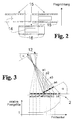
- FIG. 3 schematically shows the resulting from the inclination of the optical axes of the cameras distortion ratios within the total field of view for an off-center, tilted camera analogous to the mentioned in the above ESA report constellation of five fan-shaped cameras.
- Figure 3 neglected the surface curvature of the celestial body and considered only the tangent plane, so that the influence of the curvature of the celestial body on the image distortion in this description initially ignored.
- the superposition (assignment of pixels of the same spatial position on the surface of the celestial body) of the individual image recordings is referred to as co-registration, which must have a certain quality of coverage of the PSFs of the individual recordings of the same target area.
- the distortion effects due to the above-described inclination of the optical axis result in constant size of the sensor elements in the sensor plane to different sized object pixels, which are detected in the projection of the surface of the celestial body, and thus to different PSFs of the pixels.
- Already due to the different size of the PSFs inevitably results in a poor co-registration of the individual overlapping, overlapping images.
- the fan-shaped arrangement of cameras to increase the swath size thus leads due to the tilt (inclination) of the optical axes of the cameras to unnecessary image distortion, which significantly complicates a co-registration of the image data.
- the invention has for its object to find a new way for image capture for remote sensing of celestial bodies, which allows a large swath, without that in the combination of several separate recording systems within the male scanning field (Field of View - FoV) different distortions of the individual images arise that complicate a subsequent co-registration of the image data.
- an optically imaging instrument has a plurality of sensor arrays in order to increase the field of view of the image acquisition in the flight direction or transversely thereto while maintaining the required resolution for each flyover
- that at least two separate cameras are arranged with mutually parallel optical axes for receiving the same field of view so that they have focal planes with same content images of the field of view of the surface of the celestial body
- that in the focal plane of each camera sensor chips are arranged so that due to the limited area of the active Sensor array of at least one sensor chip in the focal plane within a first camera sampling gap is filled by arranging at least one complementarily positioned positioned active sensor array of a sensor chip in the same image focal plane of at least one second camera, so that the entire image of the field of view for each application is completely recordable.
- the sensor arrays are advantageously arranged such that the combination of image recordings of the separate cameras seamlessly images the entire field of view to be recorded for the respective application without overlaps.
- the sensor arrays can also be expediently arranged such that the combination of image recordings of the separate cameras so completely maps the entire field of view to be recorded for the respective application that at least edge regions of the combined image recordings of the sensor arrays from different cameras overlap.
- the increased ALT swath width is preferably composed by a combination of at least two sensor arrays within at least two cameras .
- the increase of the ACT swath width becomes advantageous by composing a combination of at least two sensors within at least reached two cameras.
- the entire field of view for the respective application is composed of both ALT and ACT swaths by a combination of at least two sensor arrays within at least two cameras.
- the field of view is advantageously absorbable in the ACT swath width by gaplessly arranged sensor arrays and in the ALT swath width is at least one gap between sensor arrays for recording the measured variables at different angles to the surface of the celestial body in the direction of flight available.
- all sensor arrays of the separate cameras are read out at the same time.
- at least some groups of sensor arrays covering the field of view in ACT swath width are successively readable (e.g., to successively multiply expensive optical filters for all camera beam paths).
- the parallel aligned optical axes of the separate cameras can be advantageously realized by means of a common optical system and at least a subsequent beam splitter to produce the same image focal planes are divided.
- this design can be realized only for a few separate cameras due to the light pipe in the beam splitter.
- all cameras have one and the same optical imaging system, which has the same optically corrected image field in the focal plane.
- At least one camera preferably has an optical system which has an only partially optically corrected image field for the region of the focal plane occupied by sensor arrays and thereby differs from at least one second camera used in the optical instrument, in which another region of the Focal plane (corresponding to the complementary to the first camera existing assembly with sensor arrays) is corrected.
- the invention is based on the basic idea that the disadvantage of image distortion can be circumvented by using a plurality of mutually inclined cameras to increase the field of view of a satellite-based optical instrument only if an optical system images the entire swath width to be imaged corrected to a correspondingly large focal plane.
- the optically corrected image field can be covered by a photosensitive sensor array with cost-effective available size only to a fraction, so that multiple sensor arrays must be used, but can be installed only with considerable gaps between the sensor arrays due to the connection conditions of a sensor chip.
- the invention solves this problem by the entire corrected image field is taken by a plurality of tilted (tilted) cameras with object-side parallel optical axes, each camera in another part of the same image focal planes is equipped with a photosensitive sensor array.
- the image field can be additionally corrected. It is particularly advantageous that existing instruments for the observation of celestial bodies can be retrofitted by only the optics is adjusted according to an enlarged Schwadweite, the existing, expensive and complex in the development Fokalebenenbau devise but with modified positioning of the sensors can continue to be used.
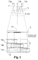
- the arrangement consists - as in Fig. 1 for three cameras 1 shown - in its basic structure of several cameras 1, which are arranged such that their optical axes 11 parallel to each other.
- the offset of the cameras 1 to each other due to the large distance (> 1 km) from the object to be imaged (surface of the celestial body 2) to no offset of the field of view 21 of the individual cameras 1 with each other.
- all the cameras 1 have the same field of view 21 on the surface of the celestial body 2 to be observed.
- the focal planes of the cameras 1 are each equipped with sensor arrays 14 only in partial areas 13a, 13b and 13c, the position of these measurable partial areas 13a, 13b and 13c in the respective focal plane 12 of each camera 1 is so different that the photosensitive surfaces of the sensor chips 14 (sensor arrays 14a, 14b and 14c) in at least one dimension of the swath width (ACT and / or ALT) cover the content-identical focal plane 12 without gaps by row by row ( ALT) or line by line (ACT) systematically (preferably with low overlap).
- the differently positioned sensor arrays 14a, 14b and 14c thus cover a larger part of the common field of view 21 (which is identical for all cameras 1) without distortions.
- Fig. 1 The generalized principle of the invention can be applied both in the direction of flight (ALT) and in the transverse direction (ACT).
- ALT direction of flight
- ACT transverse direction
- at least two focal planes 12 are required in which differently positioned sensor arrays 14 provide image data of a completely extended image field from the same visual field 21 which can be combined during co-registration of the image data without significant arithmetical equalization effort.
- combinations of the array of sensor arrays 14 for increasing the ACT swath width 31 and the ALT swath width 32 are also possible.
- At least four focal planes 21 are necessary in order to cover the extended field of view 21 without gaps. The latter will become apparent in the description below Fig. 6 explained in more detail.
- a sensor array 14 inserted in the cameras 1. This is not the case for the desired ACT error range 31.
- three sensor arrays 14 are necessary.
- the three sensor arrays 14a, 14b and 14c are arranged linearly in the ACT direction in order to record the field of view 21, which is identically imaged in the focal planes 12 of separate cameras 1, with the required ACT swath width 31.
- the sensor arrays 14a, 14b and 14c must be distributed to at least two focal planes 12 of different cameras 1, since the photosensitive sensor arrays 14 are only a fraction of the area of the sensor chips 15 and therefore can not be positioned completely within the focal plane 12 of a single camera 1, without a temporal offset of the sample (as in Fig. 2 shown) must be accepted.
- the ratio of the ACT dimension of the sensor array 14 to the ACT dimension of the entire sensor chip 15 is greater than 1: 2.
- the optically corrected focal plane 12 is elliptical in shape and sufficiently dimensioned for three sensor arrays 14 lined up.
- the described gapless arrangement of the sensor arrays 14a-14c within the virtually superimposed focal planes 12 of the separate cameras 1 does not exclude that slight overlapping of the scanned subregions 13a, 13b and 13c may occur within the same-like image of the same field of view 21.
- the distance between the sensor arrays 14a and 14c would then be smaller than an ACT sensor array length in order to close the gap in the cover of the focal plane 12 of the first camera 1 by "overlapping arrangement" of the sensor array 14b in the second camera 1 in each of the focal planes 12 of both cameras 1 the same field of view 21 is imaged by the surface of the celestial body 2.
- the simultaneously read image data from the three sensor arrays 14a-14c result in the composition in the subsequent process of co-registration a distortion-free mapping of the required swath width 3 of the dimension of an ALT sensor array width and three ACT sensor array lengths.
- the in Fig. 5 2 it is assumed that the total required ACT swath width 31 can be covered by the sensor array 14 used in the cameras 1. For the desired ALT-Schadweite 3 this was not fulfilled. In order to cover the desired total swath width 3 in the visual field 21, four sensor arrays 14 should be sufficient. In this example, the four sensor arrays 14 may also be distributed to two focal planes 12. It is assumed that the ratio of ALT dimensions from sensor array 14 to sensor chip 15 is significantly greater than 1: 2, so that a problem-free contacting of two adjacent sensor chips 15 is possible if their sensor arrays 14 have a spacing of exactly one ALT dimension of the sensor arrays 14.
- the sensor arrays 14 a and 14 c in a first camera 1 are positioned so that they are arranged in ALT swath width 32 in a row (column) and have a pitch of at most one ALT sensor dimension.
- the second camera 1 (right view of Figure 5 ) contains the sensor arrays 14b and 14d, which are arranged with respect to an existing in the focal planes 12 ALT center line 121 mirror-symmetrical to the position of the sensor arrays 14a and 14c.
- the required gap-free arrangement of the sensor arrays 14a-14d within the focal planes 12 of the separate cameras 1 virtually superimposed on the same visual field 21 also includes a slight overlap of the subareas 13a to 13d (in FIGS Fig. 5 not indicated), especially since a smaller distance between the sensor arrays 14a and 14c and 14b and 14d of less than an ALT sensor array width may be useful, for example, to check and correct the co-registration in the further processing of the image data.
- the simultaneously read-out image data from the four sensor arrays 14a-14d result in the composition in the subsequent process of co-registration a distortion-free mapping of the required swath width 3 of the dimension of an ACT sensor array length and four ALT sensor array widths.
- the total required ACT swath width 31 can be covered by two sensor array 14 inserted in the cameras 1.
- two cameras 1 top left and bottom left or right top and bottom right with respect to an ACT center line 122 of the respective focal planes 12 mirror symmetrically positioned sensor arrays 14 in the ACT direction without distance (or even with a slight overlap) and, therefore, due to the dimensions of the sensor chips 15 in the ALT direction, must have a pitch which, however, is at most an ALT sensor array width.
- eight sensor arrays 14 are required for the desired ALT Schadwte 32 in the field of view 21 (not shown) eight sensor arrays 14 are required.
- sixteen sensor arrays 14 are necessary, which are distributed on four focal planes 12 of separate cameras 1.
- two cameras 1 top left and top right, left bottom and bottom right with respect to an ALT center line 121 of the respective focal planes 12 have mirror symmetrically alternately positioned sensor arrays 14 with an ALT distance from an ALT sensor array width.
- a distortion-free imaging of the required swath width 3 of the dimension of eight ALT sensor array widths and two ACT sensor array lengths results.
- the covering of a part of the above-mentioned visual field 21 may be sufficient. This case may occur, for example, in the detection of a viewing angle-dependent reflectivity of the surface of a celestial body 2
- the cameras 1 with mutually parallel optical axes 11 may have the same or different optical imaging properties.
- the image correction of the middle camera 1 to be limited to the central part of the focal plane 12 and the image correction of the two outer cameras 1 may be limited to the correction of the lateral areas away from the optical axis 11. This can simplify the design of the individual optics.
- adapted distortion characteristics eg to take into account the surface curvature of the celestial body 2 can be adjusted.
- Another advantage of this embodiment is that the number of different camera types used can be reduced. Thus, it is possible to use a specific camera type for the respective edge region of a large swath width 3 and to use a different type of camera for the regions to be recorded which are closer to the sampling point of the nadir.
- the scan subregions 13a, 13b, 13c, etc. covered by the cameras 1 may also not be contiguously contiguous or overlapping, as the application permits, for example, in applications that detect the angular dependence of the albedo.
- This embodiment can be generated, for example, by the fact that in Fig. 7 it is assumed that the cameras 1 with the sensors 14a to 14c are arranged in the direction of flight and the central camera 1 with the sensor 14 is inactive or absent.
- the ACT swath width 31 is to be recorded as a continuous, ie continuous scanning strip. If this is the case, ACT has to perform a gapless imaging by overlapping or gapless arrangement of the sensor arrays 14 distributed over the individual cameras 1.
Landscapes
- Engineering & Computer Science (AREA)
- Multimedia (AREA)
- Signal Processing (AREA)
- Physics & Mathematics (AREA)
- General Physics & Mathematics (AREA)
- Radar, Positioning & Navigation (AREA)
- Remote Sensing (AREA)
- Studio Devices (AREA)
Applications Claiming Priority (1)
| Application Number | Priority Date | Filing Date | Title |
|---|---|---|---|
| DE102008058311A DE102008058311A1 (de) | 2008-11-18 | 2008-11-18 | Anordnung zur flugkörpergestützten Bilddatenaufnahme von der Oberfläche eines Himmelskörpers |
Publications (1)
| Publication Number | Publication Date |
|---|---|
| EP2187617A1 true EP2187617A1 (fr) | 2010-05-19 |
Family
ID=41509790
Family Applications (1)
| Application Number | Title | Priority Date | Filing Date |
|---|---|---|---|
| EP09176181A Withdrawn EP2187617A1 (fr) | 2008-11-18 | 2009-11-17 | Dispositif d'enregistrement de données d'images assistées par corps volant à partir de la surface de corps célestes |
Country Status (2)
| Country | Link |
|---|---|
| EP (1) | EP2187617A1 (fr) |
| DE (1) | DE102008058311A1 (fr) |
Cited By (2)
| Publication number | Priority date | Publication date | Assignee | Title |
|---|---|---|---|---|
| EP2851748A4 (fr) * | 2012-11-22 | 2015-09-30 | Aleksandr Nikolaevich Baryshnikov | Récepteur optique et électronique (et variantes) |
| CN110971788A (zh) * | 2018-09-28 | 2020-04-07 | 中国科学院长春光学精密机械与物理研究所 | 一种无限旋转式大视场扫描成像系统及控制系统 |
Citations (5)
| Publication number | Priority date | Publication date | Assignee | Title |
|---|---|---|---|---|
| US4833724A (en) * | 1986-08-14 | 1989-05-23 | Amada Engineering & Service Co., Inc. | Imaging device |
| US5999211A (en) * | 1995-05-24 | 1999-12-07 | Imageamerica, Inc. | Direct digital airborne panoramic camera system and method |
| WO2000066976A2 (fr) * | 1999-04-29 | 2000-11-09 | Teuchert Wolf D | Procede de prises de vues et camera photogrammetrique y relative |
| US20020163582A1 (en) * | 2001-05-04 | 2002-11-07 | Gruber Michael A. | Self-calibrating, digital, large format camera with single or mulitiple detector arrays and single or multiple optical systems |
| WO2007014293A1 (fr) * | 2005-07-25 | 2007-02-01 | The Regents Of The University Of California | Système d'imagerie numérique et procédé de production d'images en mosaïque |
Family Cites Families (1)
| Publication number | Priority date | Publication date | Assignee | Title |
|---|---|---|---|---|
| DE102008030727A1 (de) | 2008-06-27 | 2009-12-31 | Jena-Optronik Gmbh | Verfahren zur Bilddatenaufnahme bei der Beobachtung von Himmelskörpern durch satellitengestützte Instrumente |
-
2008
- 2008-11-18 DE DE102008058311A patent/DE102008058311A1/de not_active Ceased
-
2009
- 2009-11-17 EP EP09176181A patent/EP2187617A1/fr not_active Withdrawn
Patent Citations (5)
| Publication number | Priority date | Publication date | Assignee | Title |
|---|---|---|---|---|
| US4833724A (en) * | 1986-08-14 | 1989-05-23 | Amada Engineering & Service Co., Inc. | Imaging device |
| US5999211A (en) * | 1995-05-24 | 1999-12-07 | Imageamerica, Inc. | Direct digital airborne panoramic camera system and method |
| WO2000066976A2 (fr) * | 1999-04-29 | 2000-11-09 | Teuchert Wolf D | Procede de prises de vues et camera photogrammetrique y relative |
| US20020163582A1 (en) * | 2001-05-04 | 2002-11-07 | Gruber Michael A. | Self-calibrating, digital, large format camera with single or mulitiple detector arrays and single or multiple optical systems |
| WO2007014293A1 (fr) * | 2005-07-25 | 2007-02-01 | The Regents Of The University Of California | Système d'imagerie numérique et procédé de production d'images en mosaïque |
Non-Patent Citations (3)
| Title |
|---|
| "MERIS Detailed Instrument Description", ESA-REPORT, vol. 1.0, 14 April 2006 (2006-04-14), pages 17 |
| C.J. DIGENIS ET AL.: "NASA-Report", August 2001, MIT LINCOLN LABORATORY, article "Advanced Land Imager", pages: 2 |
| PROF GORDON PETRIE: "Airborne Pushbroom Line Scan An Alternative to Digital Frame Cameras A -Introduction - Heritage & Development", 1 October 2003 (2003-10-01), XP055221267, Retrieved from the Internet <URL:http://srv2.lemig.umontreal.ca/donnees/geo6343/references/PETRIE_PUSHBROOM.pdf> * |
Cited By (3)
| Publication number | Priority date | Publication date | Assignee | Title |
|---|---|---|---|---|
| EP2851748A4 (fr) * | 2012-11-22 | 2015-09-30 | Aleksandr Nikolaevich Baryshnikov | Récepteur optique et électronique (et variantes) |
| CN110971788A (zh) * | 2018-09-28 | 2020-04-07 | 中国科学院长春光学精密机械与物理研究所 | 一种无限旋转式大视场扫描成像系统及控制系统 |
| CN110971788B (zh) * | 2018-09-28 | 2022-06-21 | 中国科学院长春光学精密机械与物理研究所 | 一种无限旋转式大视场扫描成像系统及控制系统 |
Also Published As
| Publication number | Publication date |
|---|---|
| DE102008058311A1 (de) | 2010-07-22 |
Similar Documents
| Publication | Publication Date | Title |
|---|---|---|
| WO2011067150A1 (fr) | Dispositif de reproduction optique | |
| EP0529200B1 (fr) | Arrangement de capteurs d'image pour une caméra à capteurs multiples | |
| EP3403404B1 (fr) | Systeme de capture d'images stereoscopiques | |
| DE4035145A1 (de) | Optisches system zur aufteilung einer reellen abbildung | |
| DE60215223T2 (de) | Satellitengestütztes optisches beobachtungsinstrument mit zwei teleskopen | |
| DE102019008472B4 (de) | Multilinsen-Kamerasystem und Verfahren zur hyperspektralen Aufnahme von Bildern | |
| EP1312938A2 (fr) | Elément de détection de rayonnement | |
| EP2187617A1 (fr) | Dispositif d'enregistrement de données d'images assistées par corps volant à partir de la surface de corps célestes | |
| DE102006058057B3 (de) | Verfahren und Vorrichtung zur optischen Erfassung einer Struktur | |
| DE19919487C2 (de) | Aufnahmeverfahren und photogrammetrische Kamera dafür | |
| DE69413251T2 (de) | Orientierungskorrektursystem für beobachtungsgerät | |
| EP4073745A1 (fr) | Procédé et dispositif de détermination de parallaxe d'images capturées par un système de caméra à multiples objectifs | |
| DE102016008884A1 (de) | Spektroskopievorrichtung und -verfahren | |
| EP2195624A1 (fr) | Spectromètre | |
| DE102015110926A1 (de) | System zur Bestimmung einer Objektivposition | |
| EP0916971A2 (fr) | Système microoptique commutable de déviation de faisceau | |
| WO2011063939A1 (fr) | Capteur d'images, dispositif de génération d'images ainsi que spectroscope pour la spectroscopie à résolution spatiale | |
| DE19726877C2 (de) | Bildverarbeitungssystem und Verfahren zur Bildverarbeitung für Endoskope | |
| DE10208289C1 (de) | Elektronischer Bildsensor und ein Verfahren zur Auswertung | |
| DE102014105222A1 (de) | Kamera mit integriertem Spektrometer | |
| DE10247742B4 (de) | Hochauflösendes Spektrometer | |
| DE102021202164B3 (de) | Tandemblendenarchitektur zur Füllfaktorerhöhung von kompakten Multikanalabbildungssystemen | |
| DE102019101324B4 (de) | Multilinsen-Kamerasystem und Verfahren zur hyperspektralen Aufnahme von Bildern | |
| DE3927158A1 (de) | Zeilenkamera zur abbildung von objektstreifen auf photoempfindliche detektorzeilen | |
| DE69012649T2 (de) | Detektoreinheit für Infrarotüberwachungssystem. |
Legal Events
| Date | Code | Title | Description |
|---|---|---|---|
| PUAI | Public reference made under article 153(3) epc to a published international application that has entered the european phase |
Free format text: ORIGINAL CODE: 0009012 |
|
| AK | Designated contracting states |
Kind code of ref document: A1 Designated state(s): AT BE BG CH CY CZ DE DK EE ES FI FR GB GR HR HU IE IS IT LI LT LU LV MC MK MT NL NO PL PT RO SE SI SK SM TR |
|
| AX | Request for extension of the european patent |
Extension state: AL BA RS |
|
| 17P | Request for examination filed |
Effective date: 20101105 |
|
| 17Q | First examination report despatched |
Effective date: 20101129 |
|
| RIN1 | Information on inventor provided before grant (corrected) |
Inventor name: FRITSCH, HOLGER Inventor name: VOSS, BURKART |
|
| STAA | Information on the status of an ep patent application or granted ep patent |
Free format text: STATUS: THE APPLICATION IS DEEMED TO BE WITHDRAWN |
|
| 18D | Application deemed to be withdrawn |
Effective date: 20160105 |