EP2187706A2 - Dispositif électroluminescent - Google Patents
Dispositif électroluminescent Download PDFInfo
- Publication number
- EP2187706A2 EP2187706A2 EP09175161A EP09175161A EP2187706A2 EP 2187706 A2 EP2187706 A2 EP 2187706A2 EP 09175161 A EP09175161 A EP 09175161A EP 09175161 A EP09175161 A EP 09175161A EP 2187706 A2 EP2187706 A2 EP 2187706A2
- Authority
- EP
- European Patent Office
- Prior art keywords
- light
- emitting diode
- unit
- emitting
- units
- Prior art date
- Legal status (The legal status is an assumption and is not a legal conclusion. Google has not performed a legal analysis and makes no representation as to the accuracy of the status listed.)
- Withdrawn
Links
Images




Classifications
-
- H—ELECTRICITY
- H05—ELECTRIC TECHNIQUES NOT OTHERWISE PROVIDED FOR
- H05B—ELECTRIC HEATING; ELECTRIC LIGHT SOURCES NOT OTHERWISE PROVIDED FOR; CIRCUIT ARRANGEMENTS FOR ELECTRIC LIGHT SOURCES, IN GENERAL
- H05B45/00—Circuit arrangements for operating light-emitting diodes [LED]
- H05B45/10—Controlling the intensity of the light
-
- H—ELECTRICITY
- H05—ELECTRIC TECHNIQUES NOT OTHERWISE PROVIDED FOR
- H05B—ELECTRIC HEATING; ELECTRIC LIGHT SOURCES NOT OTHERWISE PROVIDED FOR; CIRCUIT ARRANGEMENTS FOR ELECTRIC LIGHT SOURCES, IN GENERAL
- H05B45/00—Circuit arrangements for operating light-emitting diodes [LED]
- H05B45/40—Details of LED load circuits
- H05B45/44—Details of LED load circuits with an active control inside an LED matrix
- H05B45/48—Details of LED load circuits with an active control inside an LED matrix having LEDs organised in strings and incorporating parallel shunting devices
-
- H—ELECTRICITY
- H05—ELECTRIC TECHNIQUES NOT OTHERWISE PROVIDED FOR
- H05B—ELECTRIC HEATING; ELECTRIC LIGHT SOURCES NOT OTHERWISE PROVIDED FOR; CIRCUIT ARRANGEMENTS FOR ELECTRIC LIGHT SOURCES, IN GENERAL
- H05B45/00—Circuit arrangements for operating light-emitting diodes [LED]
- H05B45/10—Controlling the intensity of the light
- H05B45/12—Controlling the intensity of the light using optical feedback
Definitions
- the present invention relates to a light-emitting device.
- LED Light-emitting diode
- LED is one of semiconductor elements. In the beginning, most of light-emitting diodes were used as indicator lights and light sources for outdoor display boards. Due to the advantages of high luminous power, long lifetime, and breakage-resistance, which conventional light sources barely have, light-emitting diode is praised as the innovative type of light source in the 21st century.
- the control methods of devices using light-emitting diodes as a light source can be classified into two types: constant voltage control and constant current control.
- the conventional light-emitting device 1A controlled by constant voltage, includes a light-emitting diode module 11, a capacitor 12, a plurality of resistors 13 and a constant voltage source 14.
- a constant voltage source 14 for the constancy of voltage signals inputted into light-emitting diodes, designers usually have to use capacitors with high capacitance values or more complicated rectification circuits to stabilize the voltage; however, it increases the production cost.
- the constant voltage control cannot provide a stable current.
- Light-emitting diodes depend on the combination of electrons and holes to release excess energy in the form of light so as to achieve luminant effect.
- current variation imposes a great influence on the illuminating properties of light-emitting diodes.
- the constant voltage control cannot accurately control the illuminating properties of light-emitting diodes.
- another conventional light-emitting device 1B controlled by constant current includes a light-emitting diode module 11, a capacitor 12, a plurality of resistors 13, a constant current source 15 and a detecting unit 16.
- the constant current control can provide a stable current for a light-emitting diode, in practical applications, it has to use resistors 13 as current limiting elements to absorb the power variations which are resulted from the variations of electric properties and to overcome the current variations generated from the differences among light-emitting diodes. Consequentially, it causes additional power loss.
- the present invention provides a light-emitting device driven by a variable power source without additional power loss in current limiting elements to increase the operation efficiency of power.
- a light-emitting device in accordance with the present invention includes a light-emitting diode module, a detecting circuit and a control circuit.
- the light-emitting diode module receives a variable voltage and includes a plurality of light-emitting diode units in series.
- the detecting circuit detects a light state of at least one of the light-emitting diode units of the light-emitting diode module and outputs at least a control signal.
- the control circuit includes a plurality of switch units and at least a control unit.
- the switch units are connected to each other in series, and each of the switch units is electrically connected to the corresponding light-emitting diode unit.
- the control unit adjusts the amount and/or the light state of the on-state light-emitting diodes in the corresponding light-emitting diode unit via each of the switch units in accordance with the control signal.
- a light-emitting device in accordance with the present invention includes a light-emitting diode module, a detecting circuit and a control circuit.
- the light-emitting diode module receives a variable voltage and includes a plurality of light-emitting diode units in series.
- the detecting circuit detects a light state of at least one of the light-emitting diode units of the light-emitting diode module and outputs at least a control signal.
- the control circuit includes a plurality of switch units and at least a control unit.
- the switch units are connected to each other in parallel, and each of the switch units is electrically connected to the corresponding light-emitting diode unit.
- the control unit adjusts the amount and/or the light state of the on-state light-emitting diodes in the corresponding light-emitting diode unit via each of the switch units in accordance with the control signal.
- the light-emitting device in accordance with the present invention adjusts the amount and/or the light state of the on-state light-emitting diodes in the light-emitting diode module via the control circuit.
- the present invention can operate the light-emitting diode module in a default state by changing the amount and/or the light state of the on-state light-emitting diodes so as to become a light-emitting device, which can be driven by a variable power source without additional power loss in current limiting elements and, meanwhile, increase the operation efficiency of power.
- FIG.. 1A is a schematic figure of a conventional light-emitting device controlled by constant voltage
- FIG.. 1B is a schematic figure of a conventional light-emitting device controlled by constant current
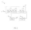
- FIG.. 2 is a schematic figure of a light-emitting device of a preferred embodiment of the present invention.
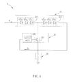
- FIG.. 3 is a schematic figure of a light-emitting device of a preferred embodiment of the present invention.
- FIGS. 4A to 4D are schematics figures of different aspects of the light-emitting device of a preferred embodiment of the present invention.
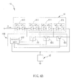
- FIGS. 5A and 5B are schematics figures of a light-emitting device of a preferred embodiment of the present invention and the alternative-current voltage corresponding to the light-emitting device.
- FIG. 2 is a schematic figure of a light-emitting device in accordance with a preferred embodiment of the present invention.
- the light-emitting device 2 includes a light-emitting diode module 21, a detecting circuit 22 and a control circuit 23.
- the light-emitting diode module 21 includes a plurality of light-emitting diode units 211 in series, and the light-emitting diode units 211 include at least a light-emitting diode respectively.
- the light-emitting diode module 21 is used to receive a variable voltage V.
- the variable voltage V can be an alternative-current voltage or a direct-current voltage.
- the variable voltage V is a voltage, which can change its own level along with the time periodically or randomly, and refers to the inconstant voltage.
- the aforementioned alternative-current voltage can be the well-known commercial power, which is an alternative current in the range from 90V to 250V, or an alternative current outputted from a power converter.
- the aforementioned direct-current voltage includes a voltage generated from a battery, a battery jar or an alternative-current voltage via a rectification circuit. However, variations of the outputted voltage levels are generated from the increase of usage period of the battery and the battery jar. And the direct-current voltage generated via the rectification circuit still has nipples. Therefore, in practice, this sort of the direct-current voltage level varies with the time yet.
- the detecting circuit 22 detects a light state of the light-emitting diode module 21 and then outputs a control signal S C .
- the detecting circuit 22 can include a resistor, a light detector, a photodiode, an induction coil, an electromagnetic induction element or a magnetoelectric induction element.
- the means of connecting the detecting circuit 22 to the light-emitting diode module 21 can be used by coupling or by electrical connection in accordance with the selected detecting circuit 22. Additionally, the detecting circuit 22 can be an integrated circuit.
- types of the light state of the light-emitting diode module described herein are, for example, the current value, the voltage value, the electric power, the luminous intensity and/or the luminous power of the light-emitting diode module.
- various types of the detecting circuit 22 can be used in accordance with needs of products or practical designs.
- the control circuit 23 is electrically connected to the light-emitting diode module 21, and adjusts the amount and/or the light state of the on-state light-emitting diodes in the light-emitting diode module 21 in accordance with the control signal Sc.
- the control circuit 23 can be a digital control circuit or an analog control circuit, and at least one of the light-emitting diode units 211 in the light-emitting diode module 21 is not controlled by the control circuit 23.
- the control circuit 23 can be an integrated circuit.
- a light-emitting diode module 31 of a light-emitting device 3 includes a first light-emitting diode unit 311 and a second light-emitting diode unit 312 connected to each other in series.
- the light-emitting diode module 31 receives a variable voltage V to drive the first light-emitting diode unit 311 and the second light-emitting diode unit 312.
- the light-emitting diodes of the first light-emitting diode unit 311 and the second light-emitting diode unit 312 can be connected in series first and then connected in parallel, and/or connected in parallel first and then connected in series.
- a detecting circuit 32 is electrically connected to the second light-emitting diode unit 312, and detects the value of the current flowing through the second light-emitting diode unit 312 to generate a control signal Sc.
- the detecting circuit 32 includes a resistor.
- a control circuit 33 includes a switch unit 331 and a control unit 332.
- the switch unit 331 is electrically connected to the second light-emitting diode unit 312.
- the control unit 322 is electrically connected to the switch unit 331 and the detecting circuit 32, and receives the control signal Sc generated by the detecting circuit 32.
- the switch unit includes a bipolar junction transistor (BJT) or a field effect transistor (FET).
- control unit 322 controls the switch unit 331 to switch between on-state and off-state by determining whether the control signal Sc is weaker than a default value.
- control circuit 33 can cut off or conduct the second light-emitting diode unit 312 to operate the light-emitting diode module 31 with a default current value in accordance with the control signal Sc.
- the first light-emitting diode unit 311 is not controlled by the control unit 33, and the detecting circuit 32 is a real-time detecting circuit.
- the first light-emitting diode unit 311 is not controlled by the control unit 33 refers to whether the first light-emitting diode unit 311 emits light is controlled by the power source and, meanwhile, the operation of the control circuit 33 does not influence whether the first light-emitting diode unit 311 emits light.
- the electrical connection still exists between the first light-emitting diode unit 311 and the control unit 33.
- the present invention can operate the light-emitting diode module in a default state by altering the amount and/or the light state of the on-state light-emitting diodes. Therefore, a power supply of the light-emitting device is not limited to provide a stable current.
- the architecture between the detecting circuit and the control circuit can be various aspects in accordance with different needs. As shown in FIGS. 4A to 4D , four exemplary application architectures of the detecting circuit and the control circuit are illustrated.
- a light-emitting diode module 41 of a light-emitting device 4A includes a plurality of the light-emitting diode units 411 connected in series, and a control circuit 43A includes a plurality of switch units 431 and a control unit 432.
- Each of the switch units 431 is electrically connected to the corresponding light-emitting diode unit 411, respectively, and each of the switch units 431 is mutually connected in parallel.
- control unit 432 can include a shifting register and a comparator.
- the shifting register is electrically connected to each of the switch units 431, respectively.
- the comparator is electrically connected to the shifting register and the detecting circuit 42, respectively, and receives the control signal generated by the detecting circuit 42.
- the control circuit 432 can cut off or conduct each of the light-emitting diode units 411 to operate the light-emitting diode module 41 with a default current value by determining whether the control signal is weaker than a default value through the comparator.
- each of the switch units 431 of a control circuit 43B is mutually connected in series and electrically connected between two light-emitting diode units 411 to control the conduction path of the current.
- the light-emitting diode module has, for example, three light-emitting diode units.
- a light-emitting device 4C includes a first detecting unit 421 and a second detecting unit 422.
- the first detecting unit 421 is electrically connected to a first light-emitting diode unit 412, and detects the light state of the first light-emitting diode unit 412.
- the second detecting unit 422 is electrically connected to a second light-emitting diode unit 413, and detects the light state of the second light-emitting diode unit 413.
- a control circuit includes a first switch unit 433, a second switch unit 434, a first control unit 435 and a second control unit 436.
- the first switch unit 433 is electrically connected to the first light-emitting diode unit 412.
- the first control unit 435 adjusts the amount and/or the light state of the on-state light-emitting diodes in the first light-emitting diode unit 412 in accordance with the light state of the first light-emitting diode unit 412.
- the second switch unit 434 is electrically connected to the second light-emitting diode unit 413.
- the second control unit 436 adjusts the amount and/or the light state of the on-state light-emitting diodes in the second light-emitting diode unit 413 in accordance with the light state of the second light-emitting diode unit 413.
- control unit adjusts the amount and/or the light state of the on-state light-emitting diodes in the light-emitting diode units in accordance with the light state of the aforementioned light-emitting diode units detected by the detecting unit. In other words, the control unit adjusts the light-emitting diode unit in accordance with the control signal outputted by the detecting unit in the same group.
- a light-emitting diode module of the light-emitting device 4D includes a first light-emitting diode unit 412, a second light-emitting diode unit 413 and a third light-emitting diode unit 414.
- a detecting circuit 42 includes a first detecting unit 421 and a second detecting unit 422.
- the first detecting unit 421 is electrically connected to the first light-emitting diode unit 412, and detects the light state of the first light-emitting diode unit 412.
- the second detecting unit 422 is electrically connected to the second light-emitting diode unit 413, and detects the light state of the second light-emitting diode unit 413.
- a control circuit 43 includes a first switch unit 433, a second switch unit 434, a first control unit 435 and a second control unit 436.
- the first switch unit 433 is electrically connected to the second light-emitting diode unit 413.
- the first control unit 435 is electrically connected to the first detecting unit 421 and the first switch unit 433, respectively, and adjusts the amount and/or the light state of the on-state light-emitting diodes in the second light-emitting diode unit 413 in accordance with the light state of the first light-emitting diode unit 412.
- the second switch unit 434 is electrically connected the third light-emitting diode unit 414.
- the second control unit 436 is electrically connected to the second detecting unit 422 and the second switch unit 434, respectively, and adjusts the amount and/or the light state of the on-state light-emitting diodes in the third light-emitting diode unit 414 in accordance with the light state of the second light-emitting diode unit 413.
- the control unit adjusts the amount and/or the light state of the on-state light-emitting diodes in the light-emitting diode unit in accordance with the light state of another light-emitting diode unit detected by the detecting unit.
- the another light-emitting diode unit described herein is a light-emitting diode unit connected to the light-emitting diode unit detected by the detecting unit in series directly or indirectly. In other words, the control unit adjusts the light-emitting diode unit in accordance with the control signal outputted by the detecting unit from the previous group.
- the current flowing through all of the light-emitting diode units is, for example but not limited to, a constant current (80mA).
- the variable voltage V is an alternative-current voltage. Furthermore, the variable voltage V can be separated into four divisions from low to high voltage. During the first division R1, the duty of the light-emitting diode module is 85%; during the second division R2, the duty of the light-emitting diode module is 70%; during the third division R3, the duty of the light-emitting diode module is 50%; and during the forth division R4, the duty of the light-emitting diode module is 25%.
- a light-emitting diode module 51 of the light-emitting device 5 includes four light-emitting diode units 511A, 511B, 511C and 511D mutually connected in series.
- the light-emitting diode units 511A, 511B and 511C respectively include four, three and two light-emitting diodes connected in parallel.
- the control circuit 53 includes a first switch unit 531A, a second switch unit 531B, a third switch unit 531C, a first control unit 532A, a second control unit 532B and the third control unit 532C.
- Each of the switch units 531A to 531C is electrically connected to the corresponding light-emitting diode units 511A to 511D, respectively, and each of the switch units 531A to 531C is mutually connected in series.
- the detecting circuit 52 includes a first detecting unit 521A, a second detecting unit 521B and a third detecting unit 521C.
- Each of the detecting units (the first detecting unit 521A, the second detecting unit 521B and the third detecting unit 521C) is coupled with the light-emitting diode units 511A to 511C, respectively, and electrically connected to the control units (the first control unit 532A, the second control unit 532B and the third control unit 532C), respectively, to detect variations of the voltage level of the variable voltage V.
- the first detecting unit 521A outputs the control signal to the first control unit 532A to cut off the first switch unit 531A so as to conduct the light-emitting diode units 511A and 511B;
- the first detecting unit 521A and the second detecting unit 521B output the control signals to the first control unit 532A and the second control unit 532B respectively to cut off the first switch unit 531A and the second switch unit 531B so as to conduct the light-emitting diode units 511A to 511C; and during the voltage level of the variable voltage V is in the forth division R4, each of the detecting unit 521A to 521C outputs the control signal to each of the control units 532A to 532C respectively
- the current flowing through each of the light-emitting diodes of the light-emitting diode unit 511A is 20mA; during the voltage level is in the second division R2, one added current flowing through each of the light-emitting diodes of the light-emitting diode unit 511B is 26.6mA; during the voltage level is in the third division R3, another added current flowing through each of the light-emitting diodes of the light-emitting diode unit 511C is 40mA; and during the voltage level is in the forth division R4, the other added current flowing through the light-emitting diodes of the light-emitting diode unit 511D is 80mA. Meanwhile, the ratio of the output power among the light-emitting diode units 511A to 511D is 17 : 18.62 : 20 :20.
- the light-emitting device can further include a capacitor or adjust the amount of the light-emitting diodes connected in series in each of the light-emitting diode units in order to extend the duties of the first division and second division. It results in the relative ratio of the duty of each division being 100%, 75%, 50% and 25%, and then causes the output power ratio of each of the light-emitting diode units becoming 20 : 20 : 20 : 20.
- the present invention can enable each of the light-emitting diode units to have similar or identical output powers by changing the amount of the on-state light-emitting diodes in each of the light-emitting diode units.
- the detecting units 521A to 521C to detect the average light power of the light-emitting diode units 511A to 511C and outputs a control signal to each of the control units 532A to 532C respectively to control the switch unit 531A to 531C so as to control the outputting light power of the light-emitting diode units 511A to 511C, and to keep the total outputting light power of the light-emitting diode module 51 at a controlled and limited level.
- the amount of the light-emitting diodes used in each of the light-emitting diode units is not limited in accordance with the present invention. And, at least one of the light-emitting diode units is not controlled by the control circuit.
- the light-emitting device of the present invention can be used as a backlight source or a lighting device, and applied to fields like mobile communication, transportation lighting and general lighting as well.
- the light-emitting device of the present invention can adjust the amount and/or the light state of the on-state light-emitting diodes in a light-emitting diode module by a control circuit.
- the present invention can operate the light-emitting diode module in a default state by changing the amount and/or the light state of the on-state light-emitting diodes so as to become a light-emitting device, which can be driven by a variable power source without additional power loss in current limiting elements and, meanwhile, increase the operation efficiency of power.
- a light-emitting device is disclosed, the device including a light-emitting diode (LED) module, a detecting circuit and a control circuit.
- LED light-emitting diode
- the light-emitting diode module receives a variable voltage.
- the detecting circuit detects a light state of the light-emitting diode module and then outputs a control signal.
- the control circuit is electrically connected to the light-emitting diode module and adjusts the amount and/or the light state of the on-state light-emitting diodes in the light-emitting diode module in accordance with the control signal.
Landscapes
- Circuit Arrangement For Electric Light Sources In General (AREA)
- Led Devices (AREA)
- Optical Communication System (AREA)
Applications Claiming Priority (2)
| Application Number | Priority Date | Filing Date | Title |
|---|---|---|---|
| TW97142959 | 2008-11-06 | ||
| TW098112376A TW201019795A (en) | 2008-11-06 | 2009-04-14 | Light-emitting device |
Publications (2)
| Publication Number | Publication Date |
|---|---|
| EP2187706A2 true EP2187706A2 (fr) | 2010-05-19 |
| EP2187706A3 EP2187706A3 (fr) | 2012-12-26 |
Family
ID=41697983
Family Applications (1)
| Application Number | Title | Priority Date | Filing Date |
|---|---|---|---|
| EP09175161A Withdrawn EP2187706A3 (fr) | 2008-11-06 | 2009-11-05 | Dispositif électroluminescent |
Country Status (3)
| Country | Link |
|---|---|
| US (1) | US20100109535A1 (fr) |
| EP (1) | EP2187706A3 (fr) |
| TW (1) | TW201019795A (fr) |
Cited By (4)
| Publication number | Priority date | Publication date | Assignee | Title |
|---|---|---|---|---|
| WO2012107293A3 (fr) * | 2011-02-10 | 2012-10-11 | Osram Ag | Commande de plusieurs sources lumineuses montées en série |
| CN104704914A (zh) * | 2012-10-02 | 2015-06-10 | 皇家飞利浦有限公司 | 用于控制发光二极管灯的装置 |
| EP2734014A4 (fr) * | 2011-07-15 | 2015-09-30 | Citizen Holdings Co Ltd | Dispositif d'éclairage à diode électroluminescente |
| EP2890222A4 (fr) * | 2012-09-26 | 2016-04-20 | Shenzhen Sendis Semiconductor Co Ltd | Appareil de pilotage à del et procédé de pilotage de celui-ci |
Families Citing this family (10)
| Publication number | Priority date | Publication date | Assignee | Title |
|---|---|---|---|---|
| TWI422278B (zh) * | 2010-05-25 | 2014-01-01 | Optromax Electronics Co Ltd | 照明裝置與其光源控制電路 |
| US10057952B2 (en) * | 2010-12-15 | 2018-08-21 | Cree, Inc. | Lighting apparatus using a non-linear current sensor and methods of operation thereof |
| TW201332390A (zh) * | 2012-01-20 | 2013-08-01 | Luxul Technology Inc | 具有高功因之無閃頻led驅動電路 |
| TW201401921A (zh) * | 2012-06-26 | 2014-01-01 | Gio Optoelectronics Corp | 發光裝置 |
| TW201406208A (zh) * | 2012-07-30 | 2014-02-01 | Luxul Technology Inc | 高效率交流led驅動電路 |
| TWI477190B (zh) * | 2012-08-10 | 2015-03-11 | Macroblock Inc | 發光二極體驅動裝置 |
| TWI496501B (zh) * | 2012-08-22 | 2015-08-11 | Macroblock Inc | 片段線性驅動的光源裝置 |
| KR101610617B1 (ko) * | 2013-05-23 | 2016-04-08 | 주식회사 실리콘웍스 | 발광 다이오드 조명 장치 |
| CN109152125A (zh) * | 2017-06-28 | 2019-01-04 | 群光电能科技股份有限公司 | 发光装置及其驱动方法 |
| CN211606885U (zh) * | 2020-02-28 | 2020-09-29 | 广州市浩洋电子股份有限公司 | 一种用于加快恒流源电感能量泄放的led调光装置 |
Family Cites Families (3)
| Publication number | Priority date | Publication date | Assignee | Title |
|---|---|---|---|---|
| US7468723B1 (en) * | 2005-03-04 | 2008-12-23 | National Semiconductor Corporation | Apparatus and method for creating large display back-lighting |
| US7649326B2 (en) * | 2006-03-27 | 2010-01-19 | Texas Instruments Incorporated | Highly efficient series string LED driver with individual LED control |
| RU2447624C2 (ru) * | 2006-09-20 | 2012-04-10 | Конинклейке Филипс Электроникс Н.В. | Система управления светоизлучающим элементом и осветительная система, содержащая ее |
-
2009
- 2009-04-14 TW TW098112376A patent/TW201019795A/zh unknown
- 2009-11-05 US US12/612,715 patent/US20100109535A1/en not_active Abandoned
- 2009-11-05 EP EP09175161A patent/EP2187706A3/fr not_active Withdrawn
Cited By (6)
| Publication number | Priority date | Publication date | Assignee | Title |
|---|---|---|---|---|
| WO2012107293A3 (fr) * | 2011-02-10 | 2012-10-11 | Osram Ag | Commande de plusieurs sources lumineuses montées en série |
| US9210772B2 (en) | 2011-02-10 | 2015-12-08 | Osram Gmbh | Actuating a plurality of series-connected luminous elements |
| EP2734014A4 (fr) * | 2011-07-15 | 2015-09-30 | Citizen Holdings Co Ltd | Dispositif d'éclairage à diode électroluminescente |
| US9485830B2 (en) | 2011-07-15 | 2016-11-01 | Citizen Holdings Co., Ltd. | LED lighting apparatus |
| EP2890222A4 (fr) * | 2012-09-26 | 2016-04-20 | Shenzhen Sendis Semiconductor Co Ltd | Appareil de pilotage à del et procédé de pilotage de celui-ci |
| CN104704914A (zh) * | 2012-10-02 | 2015-06-10 | 皇家飞利浦有限公司 | 用于控制发光二极管灯的装置 |
Also Published As
| Publication number | Publication date |
|---|---|
| TW201019795A (en) | 2010-05-16 |
| US20100109535A1 (en) | 2010-05-06 |
| EP2187706A3 (fr) | 2012-12-26 |
Similar Documents
| Publication | Publication Date | Title |
|---|---|---|
| US20100109535A1 (en) | Light-emitting device | |
| US7855515B2 (en) | High-voltage high-power constant current LED driver device | |
| US8410717B2 (en) | Apparatus, method and system for providing AC line power to lighting devices | |
| US8569956B2 (en) | Apparatus, method and system for providing AC line power to lighting devices | |
| US10375778B2 (en) | Single-segment linear constant-power LED driving circuit and method | |
| US9107264B2 (en) | Electronic control gears for LED light engine and application thereof | |
| TWI477190B (zh) | 發光二極體驅動裝置 | |
| US20100308739A1 (en) | Apparatus, Method and System for Providing AC Line Power to Lighting Devices | |
| KR101157729B1 (ko) | 정전류장치 및 그 응용 | |
| CN101916548B (zh) | 一种液晶显示器发光二极管灯管控制电路 | |
| Hu et al. | A new current-balancing method for paralleled LED strings | |
| CN102314836A (zh) | 相移控制器、相移的方法及发光装置和电子设备 | |
| US20140217918A1 (en) | Driver Circuits for Solid State Light Bulb Assemblies | |
| US8519629B2 (en) | Lighting device | |
| KR101273384B1 (ko) | 다채널 발광 다이오드 구동 장치 | |
| KR101431614B1 (ko) | 발광 다이오드 조명등 및 발광 다이오드 조명 장치 | |
| CN113891524B (zh) | 支持宽电压输入的驱动电路、驱动芯片及系统、方法 | |
| CN101737643A (zh) | 发光装置 | |
| CN211406351U (zh) | 一种分时复用的led调光装置、电路 | |
| TWI547201B (zh) | 具備多級驅動階段之發光二極體照明裝置 | |
| KR20140146888A (ko) | 발광 다이오드 조명 장치 및 그 구동 방법 | |
| KR20150031880A (ko) | 발광 다이오드 구동을 위한 능동형 밸리필 회로 | |
| US20160001699A1 (en) | System for controlling the electrical power supply of a plurality of light sources using a multiphase converter | |
| EP2945466A2 (fr) | Dispositif d'éclairage à diode électroluminescente ayant de multiples étages d'entraînement | |
| CN103108459A (zh) | 原边反馈恒流控制电路 |
Legal Events
| Date | Code | Title | Description |
|---|---|---|---|
| PUAI | Public reference made under article 153(3) epc to a published international application that has entered the european phase |
Free format text: ORIGINAL CODE: 0009012 |
|
| AK | Designated contracting states |
Kind code of ref document: A2 Designated state(s): AT BE BG CH CY CZ DE DK EE ES FI FR GB GR HR HU IE IS IT LI LT LU LV MC MK MT NL NO PL PT RO SE SI SK SM TR |
|
| AX | Request for extension of the european patent |
Extension state: AL BA RS |
|
| RIC1 | Information provided on ipc code assigned before grant |
Ipc: H05B 33/08 20060101AFI20120802BHEP |
|
| PUAL | Search report despatched |
Free format text: ORIGINAL CODE: 0009013 |
|
| AK | Designated contracting states |
Kind code of ref document: A3 Designated state(s): AT BE BG CH CY CZ DE DK EE ES FI FR GB GR HR HU IE IS IT LI LT LU LV MC MK MT NL NO PL PT RO SE SI SK SM TR |
|
| AX | Request for extension of the european patent |
Extension state: AL BA RS |
|
| RIC1 | Information provided on ipc code assigned before grant |
Ipc: H05B 33/08 20060101AFI20121119BHEP |
|
| STAA | Information on the status of an ep patent application or granted ep patent |
Free format text: STATUS: THE APPLICATION IS DEEMED TO BE WITHDRAWN |
|
| 18D | Application deemed to be withdrawn |
Effective date: 20130601 |