EP2187797B1 - Procédé permettant de faire fonctionner un lave-vaisselle - Google Patents
Procédé permettant de faire fonctionner un lave-vaisselle Download PDFInfo
- Publication number
- EP2187797B1 EP2187797B1 EP08803202.4A EP08803202A EP2187797B1 EP 2187797 B1 EP2187797 B1 EP 2187797B1 EP 08803202 A EP08803202 A EP 08803202A EP 2187797 B1 EP2187797 B1 EP 2187797B1
- Authority
- EP
- European Patent Office
- Prior art keywords
- motor
- drive
- rotation
- reversing device
- dishwasher
- Prior art date
- Legal status (The legal status is an assumption and is not a legal conclusion. Google has not performed a legal analysis and makes no representation as to the accuracy of the status listed.)
- Active
Links
Images


Classifications
-
- A—HUMAN NECESSITIES
- A47—FURNITURE; DOMESTIC ARTICLES OR APPLIANCES; COFFEE MILLS; SPICE MILLS; SUCTION CLEANERS IN GENERAL
- A47L—DOMESTIC WASHING OR CLEANING; SUCTION CLEANERS IN GENERAL
- A47L15/00—Washing or rinsing machines for crockery or tableware
- A47L15/0018—Controlling processes, i.e. processes to control the operation of the machine characterised by the purpose or target of the control
- A47L15/0049—Detection or prevention of malfunction, including accident prevention
-
- A—HUMAN NECESSITIES
- A47—FURNITURE; DOMESTIC ARTICLES OR APPLIANCES; COFFEE MILLS; SPICE MILLS; SUCTION CLEANERS IN GENERAL
- A47L—DOMESTIC WASHING OR CLEANING; SUCTION CLEANERS IN GENERAL
- A47L15/00—Washing or rinsing machines for crockery or tableware
- A47L15/42—Details
- A47L15/4214—Water supply, recirculation or discharge arrangements; Devices therefor
- A47L15/4219—Water recirculation
- A47L15/4221—Arrangements for redirection of washing water, e.g. water diverters to selectively supply the spray arms
-
- A—HUMAN NECESSITIES
- A47—FURNITURE; DOMESTIC ARTICLES OR APPLIANCES; COFFEE MILLS; SPICE MILLS; SUCTION CLEANERS IN GENERAL
- A47L—DOMESTIC WASHING OR CLEANING; SUCTION CLEANERS IN GENERAL
- A47L2401/00—Automatic detection in controlling methods of washing or rinsing machines for crockery or tableware, e.g. information provided by sensors entered into controlling devices
- A47L2401/34—Other automatic detections
-
- A—HUMAN NECESSITIES
- A47—FURNITURE; DOMESTIC ARTICLES OR APPLIANCES; COFFEE MILLS; SPICE MILLS; SUCTION CLEANERS IN GENERAL
- A47L—DOMESTIC WASHING OR CLEANING; SUCTION CLEANERS IN GENERAL
- A47L2501/00—Output in controlling method of washing or rinsing machines for crockery or tableware, i.e. quantities or components controlled, or actions performed by the controlling device executing the controlling method
- A47L2501/03—Water recirculation, e.g. control of distributing valves for redirection of water flow
-
- A—HUMAN NECESSITIES
- A47—FURNITURE; DOMESTIC ARTICLES OR APPLIANCES; COFFEE MILLS; SPICE MILLS; SUCTION CLEANERS IN GENERAL
- A47L—DOMESTIC WASHING OR CLEANING; SUCTION CLEANERS IN GENERAL
- A47L2501/00—Output in controlling method of washing or rinsing machines for crockery or tableware, i.e. quantities or components controlled, or actions performed by the controlling device executing the controlling method
- A47L2501/04—Water pressure or flow rate
-
- A—HUMAN NECESSITIES
- A47—FURNITURE; DOMESTIC ARTICLES OR APPLIANCES; COFFEE MILLS; SPICE MILLS; SUCTION CLEANERS IN GENERAL
- A47L—DOMESTIC WASHING OR CLEANING; SUCTION CLEANERS IN GENERAL
- A47L2501/00—Output in controlling method of washing or rinsing machines for crockery or tableware, i.e. quantities or components controlled, or actions performed by the controlling device executing the controlling method
- A47L2501/36—Other output
Definitions
- the invention relates to a method for operating a dishwasher.
- the DE 198 57 101 B4 discloses a dishwasher with a washing container, a circulating pump, two arranged in the washing spray arms, which can be supplied by the circulation pump with liquid, a circulation pump downstream water heater and a reversing device.
- the reversing device is controlled by a motor having a drive such that in each case one of the spray arms, none of the spray arms or both spray arms are supplied with the liquid.
- a microswitch for controlling the drive can detect the position of the reversing device.
- the publication EP 0 383 028 relates to a dishwasher with an electro-mechanical Um tenuvorraum, which is designed as a multi-way valve with a plurality of Lochschiebern.
- the perforated slides are designed as rotatable by 360 ° perforated discs and independently adjustable.
- the publication EP 1 042 982 D1 discloses a dishwasher with upper and lower spray arms, which are alternately turned on to a circulation pump by means of a shuttle valve.
- the shuttle valve includes two valve discs, which are connected to a rotatable mounting pin and can be rotated by 90 °.
- the object of the invention is to provide a method for operating a dishwasher, by means of which the reversing device can be brought into their positions in a relatively simple manner.
- Another object of the invention is to provide a dishwasher that can perform this method.
- a dishwasher comprising a rinsing container, at least two spray arms arranged within the rinsing container, a reversing device, and a drive operatively connected to the reversing device to bring the reversing device into different positions, and a control device for driving the drive and a circulating pump, which promotes depending on the adjusted position of the reversing device liquid to one of the two and / or both spray devices.
- the control device is set up to control the drive in such a way that the changeover device initially assumes a predetermined starting position and then the changeover device assumes a specific position.
- the dishwashing machine accordingly has the washing container and the spraying devices arranged in the washing container.
- the spray devices are e.g. Spray arms.
- the circulating pump conveys the liquid, which is usually referred to as rinsing liquor, to the spraying devices.
- the dishwasher comprises the reversing device, e.g. Also referred to as water switch.
- the switching device is e.g. connected between the circulation pump and supply lines for the spray devices.
- the circulating pump promotes e.g. only liquid to the spray device associated with this position.
- the reversing device has, for example, a valve body or a closing disc which closes off those inlet channels of the spraying device to which no liquid is to be delivered.
- the reversing device has a drive to adjust the individual positions of the reversing device can.
- the drive may comprise a motor, in particular an electric motor such as a stepper motor or other suitable drive means, such as. Electromagnets or pneumatic or hydraulic.
- the individual positions of the Um tenuvorraum can be adjusted by turning the motor or by rotating the shaft of the motor of the electric drive By turning the motor, for example, brings the shutter disc in the desired position.
- the Um Tavernvorraum is in the desired position, the electric motor of the drive must be rotated until the reversing device is in the desired position. So that this is possible without feedback of the current position of the reversing device to the control device, according to the invention, first of all the electric drive is controlled such that its motor brings the reversing device into the predetermined starting position.
- the starting position can correspond, for example, to one of the positions of the reversing device.
- the electric drive is driven, for example, by the control device such that its motor, starting from the starting position, rotates by the predetermined angle.
- This predetermined angle is chosen such that when the reversing device is initially in its initial position and the motor has rotated by the predetermined angle, the reversing device is in the specific position.
- a feedback that the switching device is actually in the specific position is then not necessary, which is why the dishwasher according to the invention to a corresponding feedback device, such as those from DE 198 57 101 B4 known microswitch, can do without.
- the electric drive has e.g. in addition to the motor to a converter or inverter, which is controlled by the control device and drives the motor.
- Inverters are well known and include e.g. suitable power components.
- the inverter or inverter can generate an AC voltage or a three-phase voltage.
- the zero crossings of the back emf of the motor are determined in particular by the control device while it rotates by the predetermined angle, and it becomes the electric drive in particular from the control device until a number of zero crossings of the back EMF assigned to the given angle of the motor has been determined.
- the motor has a single-pole rotor
- two zero crossings of the back EMF which is referred to as back emf in English
- back emf correspond to a complete revolution of the motor, ie an angle of 2 ⁇ or 360 °.
- the electric drive is controlled in particular by the control device such that the motor rotates in a first direction of rotation until the reversing device is in its initial position and a further rotation of the motor in the direction of blocked the first direction of rotation.
- the reversing device comprises mechanical blocking means which prevent further rotation of the motor in the direction of its first direction of rotation when reaching the starting position.
- Suitable blocking agents are e.g. a pawl or a hard stop.
- the pawl has the advantage that it blocks the engine only in one direction of rotation, here in the direction of the first direction of rotation. This makes it possible to first rotate the motor in the direction of the first direction of rotation until the reversing device has reached the starting position.
- the motor can then always be rotated in the direction of rotation different from the first direction of rotation by predetermined angles.
- At least one operating parameter of the electric drive changes.
- the operating parameter of the electric drive is, for example, an electrical current and / or an electrical power of the electric drive and / or a torque applied by the motor.
- blocking the motor increases its load and therefore also its electrical current. For example, reaching a predetermined threshold current value suggests a blockage of the motor and thus the achievement of the starting position of the reversing device.
- the electric drive is controlled in such a way that the motor rotates in the direction of the first direction of rotation until the reversing device has reached the starting position, then the electric drive can be controlled, in particular, by the control device in such a way that the motor moves by the predetermined angle in one of the first direction of rotation turns different second direction of rotation.
- the electric drive is controlled in particular by the control device such that the motor rotates alternately in the clockwise direction and in the counterclockwise direction of rotation by the predetermined angle.
- This variant is particularly suitable for so-called removable basket rinsing, in which the circulating pump successively conveys liquid to the individual rinsing devices.
- the switching device is switched between two positions back and forth by the motor turns alternately clockwise and counterclockwise by the predetermined angle. As a result, a relatively fast switching between the two spray devices is possible.
- At least one operating parameter of the electric drive is monitored while the motor rotates by the predetermined angle in order to detect a blocking of the motor. If a blocking of the engine is detected, then countermeasures are initiated. Suitable countermeasures are, for example, a lowering of the pressure of the hydraulic circuit of the dishwasher and / or a triggering of the electric drive such that the motor changes its current direction of rotation. When blocking the engine increases its load and thus the electric current or the electrical power of the electric drive. Suitable operating parameters are an electric current and / or an electric power of the electric drive.
- the monitoring can be realized, for example, in that the control device monitors the current consumption or the power consumption of the electric drive and initiates the countermeasures when a threshold value is reached.
- a self-healing of the dishwasher according to the invention can be achieved.
- the electric drive for the reversing device comprises the converter or inverter, then this can also be used for a motor for driving a washer of the dishwasher, since the drain pump is not in operation when the switching device is adjusted.
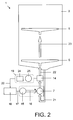
- the Fig. 1 shows a dishwasher 1 and the Fig. 2 shows a schematic diagram of the dishwasher 1, which has a washing container 2 for receiving items to be washed, eg soiled dishes and cutlery, which is classified for example in a Geschirroberkorb 3 and a dish rack 4.
- a washing container 2 for receiving items to be washed, eg soiled dishes and cutlery, which is classified for example in a Geschirroberkorb 3 and a dish rack 4.
- the washing container 2 at least two spray devices, which are formed in the case of the present embodiment as the upper and lower spray arms 5, 6, arranged for applying the washware with a liquid, which is commonly referred to as rinsing liquor.
- the liquid can be conveyed by a circulation pump 7 via a first liquid supply line 8 to the upper spray arm 5 and via a second liquid supply line 9 to the lower spray arm 6. This is in the Fig. 2 illustrated by arrows 21-23.
- the circulation pump 7 is driven for example by
- the liquid is heated, at least in a partial program step of a wash program of the dishwasher 1 by a water heater 10, which is connected to an inlet nozzle 11 to the circulation pump 7 and with outlet ports 12, 13 to the liquid supply lines 8, 9.
- the number of outlet ports 12, 13 corresponds to the number of spray arms 5, 6 or simultaneously operated groups of spray arms 5, 6.
- the funded by the circulation pump 7 liquid is therefore in the case of the present embodiment to the inlet nozzle 11 of the water heater 10 and the output port 12th , 13 via the liquid supply lines 8, 9 to the spray arms 5, 6 passed.
- the electric drive 15 is connected by means of an electrical line 17 to a control device 18 of the dishwasher 1, so that the control device 18 can control the electric drive 15 in a generally known manner and optionally also regulate.
- the control device 18 includes e.g. a suitably programmed microprocessor and is generally intended to control the dishwasher 1 so that it performs the washing program.
- the dishwasher 1 further comprises a reversing device, in particular a water diverter 14, which, e.g. arranged in the flow heater 10 or is integrally formed thereon.
- the water diverter 14 may e.g. but also be arranged in the dishwasher 1 by itself or be connected directly to the circulation pump 7.
- the spray arms 5, 6 can be alternately and / or constantly charged with the liquid, which is achieved by opening a liquid outlet and by closing another liquid outlet of the water switch 14.
- the liquid outlets of the water distributor 14 pass directly into the outlet ports 12, 13 or are identical to these.
- the water diverter 14 has a liquid inlet which, in the case of the present exemplary embodiment, adjoins or is formed by the inlet connection 11. To close the liquid outlets is in the case of the present Embodiment, a valve body or a closure disc by a drive, in particular an electric drive 19, adjusted.
- the electric drive 19 is connected to the control device 18 by means of an electrical line 20 and is controlled by the latter.
- the electric drive 19 is designed such that its direction of rotation can be changed by appropriate activation by the control device 18.
- the electric drive 19 comprises a BLDC or a BLAC motor 25, ie a three-phase synchronous motor, and an inverter or converter 24 controlling the motor 25.
- the converter 24 generates the required three-phase electrical voltage for the motor 25, so the required frequency and the required effective value of the electrical voltage.
- Suitable inverters 24 include e.g. Power semiconductors and are generally known in the art, therefore, the exact structure of the inverter 24 is not further explained.
- the electric drive 19 moves the shutter disc of the water switch 14, which is also referred to as passing through the water switch position.
- the water diverter 14 comprises a in the Fig. 3 shown and with respect to a rotational axis 26 rotatably mounted eccentric 27 with an eccentricity 28.
- the motor 25 of the electric drive 19 is connected to the eccentric 27, for example via a clutch, not shown, or a transmission, not shown, or directly in operative connection, so that the motor 25, at least indirectly the eccentric 27 rotates.
- the eccentric 27 is in turn in operative connection with the closure disk of the water switch 14, so that upon rotation of the eccentric 27 about the axis of rotation 26, the closure disk is adjusted and thus the water switch 14 occupies different positions in which the circulation pump 7, for example, only liquid to the upper spray arm. 5 or only to the lower spray arm 6 can promote.
- the water diverter 14 also has a relative to an axis 29 mounted pawl 30 with a rigid locking pin 31, by means of which the eccentric 27 can be brought into a predetermined starting position, in which the eccentricity 28 is aligned in a predetermined starting position.
- This position is in the Fig. 3 shown and corresponds to the starting position of the water switch 14.
- the starting position corresponds in particular to a position of the water distributor 14, in which the circulation pump 7 conveys only liquid to one of the spray arms 5. 6, for example to the upper spray arm 5.
- the pawl 30 is arranged so that upon rotation of the eccentric 27 in the clockwise direction, i. in the direction of an arrow 33, the eccentric 27 and its eccentricity 28, the pawl 30 with respect to the axis 29 can rotate away.
- the motor 25, the eccentric 27 rotate arbitrarily in the clockwise direction.
- This increases the counter-torque or the load of the motor 25, whereby the electric current of the electric drive 19 increases.
- the controller 18, e.g. compares the electric current of the electric drive 19 with a predetermined threshold, and stops the electric drive 19.
- the water gate 14 is in its predetermined starting position.
- control device 18 optionally controls the electric drive 19 such that its electric motor 25 rotates in a second direction of rotation, so that the eccentric 27 rotates in the clockwise direction.
- the liquid outlets of the water switch 14 such that in the case of the present embodiment in particular the circulating pump 7 conveys liquid either to the upper spray arm 5 or only to the lower spray arm 6.
- the positions of the closure disk of the water switch 14 correspond to positions of the eccentric 27. These are set in the case of the present embodiment such that starting from the preset initial position of the water switch 14, the control device 18 controls the electric drive 19 such that its motor 25 in his second direction of rotation rotates by a predetermined angle. The motor 25 thereby rotates the eccentric 27 accordingly by a predetermined angle in the clockwise direction, whereby the desired positions of the water distributor 14 set. Thus, it is only necessary that the control device 18 controls the electric drive 19 during the wash program such that its motor 25, starting from the starting position, rotates by predetermined angle with respect to the second direction of rotation.
- the predetermined angles due to the zero crossings of the back EMF (English: Back emf) of the motor 25 of the electric drive 19 are detected.
- the motor 25 comprises a single-pole rotor, as provided in the present embodiment, then two zero crossings of the back EMF correspond to one complete revolution of the motor 25.
- the zero crossings of the back EMF of the motor 25 necessary for the desired rotation of the motor 25 in its second direction of rotation are e.g. stored in a memory, not shown, of the control device 18.
- the controller 18 may rotate it by the predetermined angle due to measured zero crossings of the back EMF of the motor 25 to bring the water gate 14 and its shutter disc to the desired positions, respectively.
- the dishwasher 1 it is provided to operate the dishwasher 1 in the so-called change basket washing mode, at least in a partial washing program step. In this operating mode, only one of the two spray arms 5, 6 is alternately charged with liquid. If the dishwasher 1 is in the change-over washing mode, then the control device 18 controls the electric drive 19 such that its motor 25 initially from its initial position, which corresponds in the case of the present embodiment, the position of the water switch 14, in which the circulating pump 7 promotes only liquid to the upper spray arm 5, rotates at the predetermined angle in the clockwise direction to the To bring water diverter 14 in a position in which the circulation pump 7 promotes only liquid to the lower spray arm 5.
- control device 18 controls the electric drive 19 such that the motor 25 rotates in the counterclockwise direction of rotation by the predetermined angle, whereby the water switch 14 is brought back into the position in which the circulation pump 7 only liquid to the upper spray arm. 5 promotes. This is repeated as many times as desired.
- the electric drive 19 starting from the initial position controls such that its first motor 25 rotates from its initial position by the predetermined angle in the clockwise direction to bring the water distributor 14 in a position, in which the circulation pump 7 promotes only liquid to the lower spray arm 5.
- the control device 18 controls the electric drive 19 such that the motor 25 continues to rotate in the clockwise direction by a further predetermined angle to bring the water switch 14 back into the position in which the circulation pump 7 only liquid to the upper Spray arm 5 promotes. Since the eccentric 27 is not blocked by the pawl 30, when the motor 25 rotates in the clockwise direction, this program can be repeated as desired of any.
- the control device 18 monitors the magnitude of the electrical current of the electric drive 19, for example its effective value. If the motor 25 is blocked due to a too high counter-torque on the shutter disk, for example because a foreign body obstructs or blocks the movement of the shutter disk, then the electric current of the electric drive increases. Thus, it is possible, due to monitoring of the electrical current of the electric drive 19 to conclude an inadmissible operating state, so that, for example, the control device 18 can initiate appropriate countermeasures. Suitable countermeasures are, for example, a lowering of the pressure in the hydraulic circuit of the dishwasher 1 or a triggering of the electric drive 19 such that it changes its current direction of rotation. The monitoring of the electric current For example, it can be realized such that the control device 18 compares the effective value of the electric current with a predetermined maximum value and initiates the countermeasures when the effective value of the electric current exceeds the maximum value.
- the Fig. 4 shows a part of an alternative water diverter 14a, which can be used instead of the water diverter 14 for the dishwasher 1.
- the water switch 14 a differs substantially from the water switch 14 in that the water switch 14 a no pawl 30, but has a stationary fixed stop 32.
- the eccentric 27 can perform substantially only one full revolution.
- the control device 18 in the case of the present embodiment e.g. at the beginning of a washing program or a program step of the washing program, the control device 18, the electric drive 19 so that the motor 25 rotates in its first rotational direction, whereby the eccentric 27 rotates counterclockwise rotation until it stops the hard stop 32.
- the control device 18 due to the increasing electric current of the electric drive 19 and stops it.
- the water diverter 14a is in its predetermined starting position, in the e.g. the circulation pump can only convey liquid to the upper spray arm 5.
- control device 18 optionally controls the electric drive 19 such that its electric motor 25 first rotates in its second direction of rotation, so that the eccentric 27 rotates in the clockwise direction until the eccentric 27 occupies another position of the water switch 14 a, in the circulating pump 7, for example can only promote fluid to the lower spray arm 6.
- the required angle of the motor 25 to be traversed is determined by the control device 18 on the basis of predetermined zero crossings of the back EMF of the motor 25 of the electric drive 19.
- the control device 18, the electric Drive 19 for an adjustment of the water gate 14a such that its motor 25 optionally changes its direction of rotation and rotates in the changed direction of rotation, for example by a further predetermined angle.
Landscapes
- Engineering & Computer Science (AREA)
- Water Supply & Treatment (AREA)
- Washing And Drying Of Tableware (AREA)
Claims (28)
- Procédé destiné au fonctionnement d'un lave-vaisselle (1) qui comprend un réservoir de lavage (2), au moins deux dispositifs d'arrosage (5, 6) disposés à l'intérieur du réservoir de lavage (2), un dispositif d'inversion de marche (14, 14a) et un entraînement (19) en liaison active avec le dispositif d'inversion de marche, muni d'un moteur électrique (25), afin d'amener le dispositif d'inversion de marche (14, 14a) dans différentes positions, ainsi qu'une pompe de circulation (7), laquelle, selon la position réglée du dispositif d'inversion de marche (14, 14a), transporte du liquide vers l'un des deux et/ou vers les deux dispositifs d'arrosage (5, 6), présentant les étapes de procédé suivantes :commande de l'entraînement (19) de telle manière que le moteur électrique (25) tourne dans un premier sens de rotation jusqu'à ce que le dispositif d'inversion de marche (14, 14a) prenne une position initiale prédéfinie et qu'une rotation supplémentaire du moteur électrique (25) en direction du premier sens de rotation soit bloquée, etcommande de l'entraînement (19) de manière à ce que, partant de la position initiale, le dispositif d'inversion de marche (14, 14a) prenne une position déterminée.
- Procédé selon la revendication 1, caractérisé en ce que la commande de la position déterminée est réalisée sans information en retour.
- Procédé selon la revendication 1 ou 2, caractérisé en ce que la commande est réalisée par réglage d'une valeur prédéfinie, notamment par rotation suivant un angle prédéfini.
- Procédé selon l'une quelconque des revendications 1 à 3, caractérisé en ce que la position initiale correspond à l'une des positions du dispositif d'inversion de marche (14).
- Procédé selon l'une quelconque des revendications 1 à 4, caractérisé en ce que des passages par zéro de la force contre-électromotrice du moteur (25) sont détectés pendant que celui-ci tourne suivant l'angle prédéfini, et commande de l'entraînement (19) jusqu'à ce qu'un nombre de passages par zéro de la force contre-électromotrice, attribué à l'angle prédéfini du moteur (25), soit détecté.
- Procédé selon la revendication 1, caractérisé en ce que le dispositif d'inversion de marche (14, 14a) comprend des moyens de blocage mécaniques (29 - 32) qui empêchent une poursuite de la rotation du moteur (25) en direction de son premier sens de rotation lorsque la position initiale est atteinte.
- Procédé selon la revendication 6, caractérisé en ce que les moyens de blocage (29 - 32) sont réalisés comme cliquet d'arrêt (29 - 31) ou comme butée fixe (32).
- Procédé selon l'une quelconque des revendications 1 à 7, caractérisé par l'identification de l'obtention de la position initiale du dispositif d'inversion de marche (14, 14a) en raison d'au moins un paramètre de fonctionnement de l'entraînement électrique (19) et caractérisé par l'arrêt de l'entraînement électrique (19).
- Procédé selon la revendication 8, caractérisé en ce que le paramètre de fonctionnement de l'entraînement (19) est un courant électrique et/ou une puissance électrique de l'entraînement électrique (19) et /ou un couple appliqué par le moteur (25).
- Procédé selon l'une quelconque des revendications 1 à 9, présentant la commande de l'entraînement (19) de telle manière que le moteur (25) tourne suivant un angle prédéfini dans un deuxième sens de rotation (33) différent du premier sens de rotation.
- Procédé selon l'une quelconque des revendications 1 à 10, caractérisé par une commande supplémentaire de l'entraînement électrique (19) de manière à ce que le moteur (25) tourne suivant l'angle prédéfini, en alternance dans le sens horaire et dans le sens inverse horaire.
- Procédé selon l'une quelconque des revendications 1 à 11, caractérisé par une surveillance supplémentaire au moins d'un paramètre de fonctionnement de l'entraînement (19) pendant que le moteur (25) tourne suivant l'angle prédéfini, afin d'identifier un blocage du moteur (25), et caractérisé par l'introduction de contre-mesures lorsqu'un moteur bloqué (25) est identifié.
- Procédé selon la revendication 12, caractérisé en ce que le paramètre de fonctionnement de l'entraînement (19) est un courant électrique et/ou une puissance électrique de l'entraînement électrique.
- Procédé selon l'une quelconque des revendications 1 à 13 caractérisé en ce que suite à l'enregistrement d'un blocage de l'entraînement (19) une baisse de la pression du circuit hydraulique du lave-vaisselle (1) est réalisée et/ou en ce qu'une commande de l'entraînement (19) a lieu de manière à ce que le moteur (25) tourne en sens contraire du sens de rotation momentané.
- Lave-vaisselle, présentant au moins un réservoir de lavage (2), au moins deux dispositifs d'arrosage (5, 6) disposés à l'intérieur du réservoir de lavage (2), un dispositif d'inversion de marche (14, 14a) et un entraînement (19) en liaison active avec le dispositif d'inversion de marche (14, 14a), muni d'un moteur électrique (25), afin d'amener le dispositif d'inversion de marche (14, 14a) dans différentes positions, un dispositif de commande (18) destiné à commander l'entraînement électrique (19) et une pompe de circulation (7), laquelle, selon la position réglée du dispositif d'inversion de marche (14, 14a), transporte du liquide vers l'un des deux et/ou vers les deux dispositifs d'arrosage (5, 6), caractérisé en ce que le dispositif de commande (18) est agencé pour commander l'entraînement (19) de manière à ce que le moteur électrique (25) tourne dans un premier sens de rotation jusqu'à ce que le dispositif d'inversion de marche (14, 14a) prenne d'abord une position initiale prédéfinie et qu'une rotation supplémentaire du moteur électrique (25) en direction du premier sens de rotation soit bloquée, et qu'ensuite le dispositif d'inversion de marche (14, 14a) prenne une position déterminée.
- Lave-vaisselle selon la revendication 15, caractérisé en ce que le lave-vaisselle (1) est réalisé pour la commande de la position déterminée sans information en retour.
- Lave-vaisselle selon la revendication 15, caractérisé en ce que la commande est réalisée par réglage d'une valeur prédéfinie, notamment par rotation suivant un angle prédéfini.
- Lave-vaisselle selon l'une quelconque des revendications 15 à 17, caractérisé en ce que la position initiale correspond à l'une des positions du dispositif d'inversion de marche (14).
- Lave-vaisselle selon l'une quelconque des revendications 15 à 18, caractérisé en ce que le dispositif de commande (18) est agencé pour détecter des passages par zéro de la force contre-électromotrice du moteur (25) pendant que celui-ci tourne suivant l'angle prédéfini, et en ce que le dispositif de commande (18) est agencé pour commander l'entraînement (19) jusqu'à ce qu'un nombre, attribué à l'angle prédéfini du moteur (25), de passages par zéro de la force contre-électromotrice soit détecté.
- Lave-vaisselle selon la revendication 15, caractérisé en ce que le dispositif d'inversion de marche (14, 14a) comprend des moyens de blocage mécaniques (29 - 32) qui empêchent une poursuite de la rotation du moteur (25) en direction de son premier sens de rotation lorsque la position initiale est atteinte.
- Lave-vaisselle selon la revendication 20, caractérisé en ce que les moyens de blocage (29 - 32) sont réalisés comme cliquet d'arrêt (29 - 31) ou comme butée fixe (32).
- Lave-vaisselle selon l'une quelconque des revendications 15 à 19, caractérisé en ce que le dispositif de commande (18) est agencé pour identifier l'obtention de la position initiale du dispositif d'inversion de marche (14, 14a) en raison d'au moins un paramètre de fonctionnement de l'entraînement électrique (19) et pour arrêter l'entraînement (19) en fonction du paramètre de fonctionnement.
- Lave-vaisselle selon la revendication 22, caractérisé en ce que le paramètre de fonctionnement de l'entraînement électrique (19) est un courant électrique et/ou une puissance électrique de l'entraînement électrique et/ou un couple appliqué par le moteur (25).
- Lave-vaisselle selon l'une quelconque des revendications 15 à 23, caractérisé en ce que le dispositif de commande (18) est agencé pour commander l'entraînement (19) de manière à ce que le moteur (25) tourne suivant l'angle prédéfini dans un deuxième sens de rotation (33) différent du premier sens de rotation.
- Lave-vaisselle selon l'une quelconque des revendications 15 à 24, caractérisé en ce que le dispositif de commande (18) est agencé pour commander l'entraînement (19) de manière à ce que le moteur (25) tourne suivant l'angle prédéfini, en alternance dans le sens horaire et dans le sens inverse horaire.
- Lave-vaisselle selon l'une quelconque des revendications 15 à 23, caractérisé en ce que le dispositif de commande (18) est agencé pour surveiller au moins un paramètre de fonctionnement de l'entraînement (19) pendant que le moteur (25) tourne suivant l'angle prédéfini, afin d'identifier un blocage du moteur (25) et en ce que le dispositif de commande (18) est agencé pour introduire des contre-mesures lorsque le dispositif de commande (18) a identifié un moteur bloqué (25).
- Lave-vaisselle selon la revendication 26, caractérisé en ce que le paramètre de fonctionnement de l'entraînement (19) est un courant électrique et/ou une puissance électrique de l'entraînement (19) électrique.
- Lave-vaisselle selon la revendication 20 ou 27, caractérisé en ce que suite à l'enregistrement d'un blocage de l'entraînement (19) une baisse de la pression du circuit hydraulique du lave-vaisselle (1) est réalisée et/ou en ce qu'une commande de l'entraînement (19) a lieu de manière à ce que le moteur (25) tourne en sens contraire du sens de rotation momentané.
Applications Claiming Priority (2)
| Application Number | Priority Date | Filing Date | Title |
|---|---|---|---|
| DE102007041299A DE102007041299A1 (de) | 2007-08-31 | 2007-08-31 | Verfahren zum Betreiben einer Geschirrspülmaschine |
| PCT/EP2008/061086 WO2009027372A1 (fr) | 2007-08-31 | 2008-08-25 | Procédé permettant de faire fonctionner un lave-vaisselle |
Publications (2)
| Publication Number | Publication Date |
|---|---|
| EP2187797A1 EP2187797A1 (fr) | 2010-05-26 |
| EP2187797B1 true EP2187797B1 (fr) | 2013-12-11 |
Family
ID=39929800
Family Applications (1)
| Application Number | Title | Priority Date | Filing Date |
|---|---|---|---|
| EP08803202.4A Active EP2187797B1 (fr) | 2007-08-31 | 2008-08-25 | Procédé permettant de faire fonctionner un lave-vaisselle |
Country Status (5)
| Country | Link |
|---|---|
| US (1) | US8834644B2 (fr) |
| EP (1) | EP2187797B1 (fr) |
| CN (1) | CN101784221B (fr) |
| DE (1) | DE102007041299A1 (fr) |
| WO (1) | WO2009027372A1 (fr) |
Families Citing this family (9)
| Publication number | Priority date | Publication date | Assignee | Title |
|---|---|---|---|---|
| US8852351B2 (en) * | 2010-10-20 | 2014-10-07 | Whirlpool Corporation | Dishwasher with wash load detection |
| PL2532295T3 (pl) * | 2012-09-25 | 2017-05-31 | V-Zug Ag | Sprzęt gospodarstwa domowego ze zwrotnicą wody |
| US9763552B2 (en) | 2014-06-12 | 2017-09-19 | Haier Us Appliance Solutions, Inc. | Dishwasher diverter valves with continuous calibration |
| BR112017009011A2 (pt) * | 2014-12-18 | 2018-01-30 | Electrolux Appliances AB | máquina de lavar louça |
| DE102017208527A1 (de) * | 2017-05-19 | 2018-11-22 | BSH Hausgeräte GmbH | Wasserführendes Haushaltsgerät und Verfahren zum Betreiben eines wasserführenden Haushaltsgeräts |
| DE102017223261A1 (de) * | 2017-07-18 | 2019-01-24 | BSH Hausgeräte GmbH | Geschirrspülmaschine mit zumindest einer im Betrieb automatisch aufstellbaren Tür |
| DE102019135316A1 (de) * | 2019-12-19 | 2021-06-24 | Minebea Mitsumi Inc. | Stelleinheit und Verfahren zum Verstellen eines Stellgliedes |
| CN112716409B (zh) * | 2021-01-07 | 2022-07-15 | 佛山市顺德区美的洗涤电器制造有限公司 | 用于洗碗机的控制方法、处理器、装置、洗碗机以及介质 |
| EP4198351A1 (fr) | 2021-12-20 | 2023-06-21 | Flender GmbH | Engrenage pourvu d'élément de pulvérisation d'huile |
Family Cites Families (9)
| Publication number | Priority date | Publication date | Assignee | Title |
|---|---|---|---|---|
| DE3209542C1 (de) * | 1982-03-16 | 1992-05-07 | Bosch-Siemens Hausgeräte GmbH, 7000 Stuttgart | Geschirrspülmaschine |
| EP0383028A3 (fr) * | 1989-02-14 | 1992-05-06 | Licentia Patent-Verwaltungs-GmbH | Lave-vaisselle comportant un dispositif de renversement électromécanique |
| IT1271243B (it) * | 1994-10-05 | 1997-05-27 | Candy Spa | Dispositivo di comando per un dispositivo valvolare di controllo del flusso di liquido di lavaggio, per alimentare selettivamente le giranti irroratrici di una macchina lavastoviglie |
| DE19857101B4 (de) | 1998-12-10 | 2004-04-01 | BSH Bosch und Siemens Hausgeräte GmbH | Haushalt-Geschirrspülmaschine |
| DE19914359C5 (de) * | 1999-03-30 | 2006-01-05 | Whirlpool Corp., Benton Harbor | Geschirrspülmaschine mit oberem und unterem Sprüharm |
| DE10133130A1 (de) * | 2001-07-07 | 2003-01-16 | Miele & Cie | Umwälzpumpe mit/ohne Heizungseinrichtung |
| DE10225610B4 (de) * | 2002-06-07 | 2006-12-28 | Trinamic Motion Control Gmbh & Co. Kg | Verfahren und Schaltungsanordnung zum Betreiben eines Schrittmotors |
| US7475696B2 (en) | 2003-06-17 | 2009-01-13 | Whirlpool Corporation | Dishwasher having valved third-level sprayer |
| CN100431464C (zh) * | 2004-11-26 | 2008-11-12 | 乐金电子(天津)电器有限公司 | 洗碗机的流路转换部漏水防止结构 |
-
2007
- 2007-08-31 DE DE102007041299A patent/DE102007041299A1/de not_active Withdrawn
-
2008
- 2008-08-25 US US12/674,724 patent/US8834644B2/en active Active
- 2008-08-25 WO PCT/EP2008/061086 patent/WO2009027372A1/fr not_active Ceased
- 2008-08-25 CN CN200880104428.3A patent/CN101784221B/zh active Active
- 2008-08-25 EP EP08803202.4A patent/EP2187797B1/fr active Active
Also Published As
| Publication number | Publication date |
|---|---|
| CN101784221A (zh) | 2010-07-21 |
| DE102007041299A1 (de) | 2009-03-05 |
| US20110120500A1 (en) | 2011-05-26 |
| US8834644B2 (en) | 2014-09-16 |
| EP2187797A1 (fr) | 2010-05-26 |
| WO2009027372A1 (fr) | 2009-03-05 |
| CN101784221B (zh) | 2012-12-26 |
Similar Documents
| Publication | Publication Date | Title |
|---|---|---|
| EP2187797B1 (fr) | Procédé permettant de faire fonctionner un lave-vaisselle | |
| EP2185054B1 (fr) | Lave-vaisselle et procede pour faire fonctionner un lave-vaisselle | |
| EP1404208B1 (fr) | Lave-vaisselle a bras gicleurs et pompe de recirculation | |
| EP2108299B1 (fr) | Automate de programmation doté d'une récupération de chaleur à partir d'eaux usées | |
| EP2146614B1 (fr) | Procédé de reconnaissance de la position d'un élément de fermeture dans un mécanisme répartiteur d'eau | |
| DE10065571B4 (de) | Geschirrspülmaschine | |
| DE69601889T2 (de) | Elektromechanische Steuervorrichtung für einen Geschirrspüler mit alternierendem Fluss | |
| EP1935319B1 (fr) | Appareil ménager à circulation d'eau doté d'un dispositif d'ajout pour produit de nettoyage | |
| EP1935317A2 (fr) | Appareil ménager à circulation d'eau doté d'un dispositif d'ajout pour produit de nettoyage | |
| EP2413774B1 (fr) | Procédé pour faire fonctionner un appareil ménager à circulation d'eau | |
| EP1532306B1 (fr) | Appareil electromenager | |
| WO2003053210A1 (fr) | Unite de changement de marche, notamment pour un lave-vaisselle | |
| DE102014101384A1 (de) | Geschirrspüler mit variablem Strömungsgeschwindigkeits-Ventil | |
| DE102006031555A1 (de) | Geschirrspülmaschine und Verfahren zu deren Steuerung | |
| DE102005049892B3 (de) | Schaltung zur Ansteuerung eines Geräts zur Wäschebehandlung | |
| DE10246407A1 (de) | Ventilaggregat, ggf. Umlenk-Ventilaggregat, insbesondere für eine Geschirrspül- und Geschirrtrockner-Maschine | |
| EP1935314A2 (fr) | Dispositif de réglage de l'aiguillage du circuit d'eau d'un appareil ménager à laver et procédé de réglage de l'aiguillage du circuit d'eau à l'aide d'un moteur synchrone | |
| DE20008430U1 (de) | Elektrische Steuereinrichtung einer Waschmaschine oder eines Wäschetrockners | |
| DE102014200383B4 (de) | Wasserführendes Haushaltsgerät und Verfahren zum Betreiben eines wasserführenden Haushaltsgeräts | |
| DE1931510C3 (de) | Waschautomat | |
| WO2026073934A1 (fr) | Pompe à chaleur, lave-vaisselle à usage domestique et unité de commande pour faire fonctionner une pompe à chaleur | |
| EP3305142A1 (fr) | Machine à café | |
| DE102005011731A1 (de) | Einphasen-Synchronmotor | |
| EP2573932A1 (fr) | Moteur sans balais doté d'un réglage SFOC | |
| WO2018206563A1 (fr) | Distributeur de liquide commutable pourvu d'élément de ressort |
Legal Events
| Date | Code | Title | Description |
|---|---|---|---|
| PUAI | Public reference made under article 153(3) epc to a published international application that has entered the european phase |
Free format text: ORIGINAL CODE: 0009012 |
|
| 17P | Request for examination filed |
Effective date: 20100331 |
|
| AK | Designated contracting states |
Kind code of ref document: A1 Designated state(s): AT BE BG CH CY CZ DE DK EE ES FI FR GB GR HR HU IE IS IT LI LT LU LV MC MT NL NO PL PT RO SE SI SK TR |
|
| AX | Request for extension of the european patent |
Extension state: AL BA MK RS |
|
| DAX | Request for extension of the european patent (deleted) | ||
| GRAP | Despatch of communication of intention to grant a patent |
Free format text: ORIGINAL CODE: EPIDOSNIGR1 |
|
| INTG | Intention to grant announced |
Effective date: 20130729 |
|
| GRAS | Grant fee paid |
Free format text: ORIGINAL CODE: EPIDOSNIGR3 |
|
| GRAA | (expected) grant |
Free format text: ORIGINAL CODE: 0009210 |
|
| AK | Designated contracting states |
Kind code of ref document: B1 Designated state(s): AT BE BG CH CY CZ DE DK EE ES FI FR GB GR HR HU IE IS IT LI LT LU LV MC MT NL NO PL PT RO SE SI SK TR |
|
| REG | Reference to a national code |
Ref country code: GB Ref legal event code: FG4D Free format text: NOT ENGLISH |
|
| REG | Reference to a national code |
Ref country code: CH Ref legal event code: EP |
|
| REG | Reference to a national code |
Ref country code: AT Ref legal event code: REF Ref document number: 644020 Country of ref document: AT Kind code of ref document: T Effective date: 20140115 |
|
| REG | Reference to a national code |
Ref country code: IE Ref legal event code: FG4D Free format text: LANGUAGE OF EP DOCUMENT: GERMAN |
|
| REG | Reference to a national code |
Ref country code: DE Ref legal event code: R096 Ref document number: 502008011062 Country of ref document: DE Effective date: 20140206 |
|
| REG | Reference to a national code |
Ref country code: NL Ref legal event code: VDEP Effective date: 20131211 |
|
| PG25 | Lapsed in a contracting state [announced via postgrant information from national office to epo] |
Ref country code: NL Free format text: LAPSE BECAUSE OF FAILURE TO SUBMIT A TRANSLATION OF THE DESCRIPTION OR TO PAY THE FEE WITHIN THE PRESCRIBED TIME-LIMIT Effective date: 20131211 Ref country code: FI Free format text: LAPSE BECAUSE OF FAILURE TO SUBMIT A TRANSLATION OF THE DESCRIPTION OR TO PAY THE FEE WITHIN THE PRESCRIBED TIME-LIMIT Effective date: 20131211 Ref country code: SE Free format text: LAPSE BECAUSE OF FAILURE TO SUBMIT A TRANSLATION OF THE DESCRIPTION OR TO PAY THE FEE WITHIN THE PRESCRIBED TIME-LIMIT Effective date: 20131211 Ref country code: NO Free format text: LAPSE BECAUSE OF FAILURE TO SUBMIT A TRANSLATION OF THE DESCRIPTION OR TO PAY THE FEE WITHIN THE PRESCRIBED TIME-LIMIT Effective date: 20140311 Ref country code: HR Free format text: LAPSE BECAUSE OF FAILURE TO SUBMIT A TRANSLATION OF THE DESCRIPTION OR TO PAY THE FEE WITHIN THE PRESCRIBED TIME-LIMIT Effective date: 20131211 Ref country code: LT Free format text: LAPSE BECAUSE OF FAILURE TO SUBMIT A TRANSLATION OF THE DESCRIPTION OR TO PAY THE FEE WITHIN THE PRESCRIBED TIME-LIMIT Effective date: 20131211 |
|
| REG | Reference to a national code |
Ref country code: LT Ref legal event code: MG4D |
|
| PG25 | Lapsed in a contracting state [announced via postgrant information from national office to epo] |
Ref country code: CY Free format text: LAPSE BECAUSE OF FAILURE TO SUBMIT A TRANSLATION OF THE DESCRIPTION OR TO PAY THE FEE WITHIN THE PRESCRIBED TIME-LIMIT Effective date: 20131211 Ref country code: LV Free format text: LAPSE BECAUSE OF FAILURE TO SUBMIT A TRANSLATION OF THE DESCRIPTION OR TO PAY THE FEE WITHIN THE PRESCRIBED TIME-LIMIT Effective date: 20131211 |
|
| PG25 | Lapsed in a contracting state [announced via postgrant information from national office to epo] |
Ref country code: EE Free format text: LAPSE BECAUSE OF FAILURE TO SUBMIT A TRANSLATION OF THE DESCRIPTION OR TO PAY THE FEE WITHIN THE PRESCRIBED TIME-LIMIT Effective date: 20131211 Ref country code: IS Free format text: LAPSE BECAUSE OF FAILURE TO SUBMIT A TRANSLATION OF THE DESCRIPTION OR TO PAY THE FEE WITHIN THE PRESCRIBED TIME-LIMIT Effective date: 20140411 |
|
| PG25 | Lapsed in a contracting state [announced via postgrant information from national office to epo] |
Ref country code: PL Free format text: LAPSE BECAUSE OF FAILURE TO SUBMIT A TRANSLATION OF THE DESCRIPTION OR TO PAY THE FEE WITHIN THE PRESCRIBED TIME-LIMIT Effective date: 20131211 Ref country code: SK Free format text: LAPSE BECAUSE OF FAILURE TO SUBMIT A TRANSLATION OF THE DESCRIPTION OR TO PAY THE FEE WITHIN THE PRESCRIBED TIME-LIMIT Effective date: 20131211 Ref country code: CZ Free format text: LAPSE BECAUSE OF FAILURE TO SUBMIT A TRANSLATION OF THE DESCRIPTION OR TO PAY THE FEE WITHIN THE PRESCRIBED TIME-LIMIT Effective date: 20131211 Ref country code: PT Free format text: LAPSE BECAUSE OF FAILURE TO SUBMIT A TRANSLATION OF THE DESCRIPTION OR TO PAY THE FEE WITHIN THE PRESCRIBED TIME-LIMIT Effective date: 20140411 Ref country code: ES Free format text: LAPSE BECAUSE OF FAILURE TO SUBMIT A TRANSLATION OF THE DESCRIPTION OR TO PAY THE FEE WITHIN THE PRESCRIBED TIME-LIMIT Effective date: 20131211 Ref country code: RO Free format text: LAPSE BECAUSE OF FAILURE TO SUBMIT A TRANSLATION OF THE DESCRIPTION OR TO PAY THE FEE WITHIN THE PRESCRIBED TIME-LIMIT Effective date: 20131211 |
|
| REG | Reference to a national code |
Ref country code: DE Ref legal event code: R097 Ref document number: 502008011062 Country of ref document: DE |
|
| PLBE | No opposition filed within time limit |
Free format text: ORIGINAL CODE: 0009261 |
|
| STAA | Information on the status of an ep patent application or granted ep patent |
Free format text: STATUS: NO OPPOSITION FILED WITHIN TIME LIMIT |
|
| PG25 | Lapsed in a contracting state [announced via postgrant information from national office to epo] |
Ref country code: DK Free format text: LAPSE BECAUSE OF FAILURE TO SUBMIT A TRANSLATION OF THE DESCRIPTION OR TO PAY THE FEE WITHIN THE PRESCRIBED TIME-LIMIT Effective date: 20131211 |
|
| 26N | No opposition filed |
Effective date: 20140912 |
|
| REG | Reference to a national code |
Ref country code: DE Ref legal event code: R097 Ref document number: 502008011062 Country of ref document: DE Effective date: 20140912 |
|
| PG25 | Lapsed in a contracting state [announced via postgrant information from national office to epo] |
Ref country code: SI Free format text: LAPSE BECAUSE OF FAILURE TO SUBMIT A TRANSLATION OF THE DESCRIPTION OR TO PAY THE FEE WITHIN THE PRESCRIBED TIME-LIMIT Effective date: 20131211 |
|
| REG | Reference to a national code |
Ref country code: CH Ref legal event code: PFA Owner name: BSH HAUSGERAETE GMBH, DE Free format text: FORMER OWNER: BSH BOSCH UND SIEMENS HAUSGERAETE GMBH, DE |
|
| PG25 | Lapsed in a contracting state [announced via postgrant information from national office to epo] |
Ref country code: LU Free format text: LAPSE BECAUSE OF FAILURE TO SUBMIT A TRANSLATION OF THE DESCRIPTION OR TO PAY THE FEE WITHIN THE PRESCRIBED TIME-LIMIT Effective date: 20140825 Ref country code: MC Free format text: LAPSE BECAUSE OF FAILURE TO SUBMIT A TRANSLATION OF THE DESCRIPTION OR TO PAY THE FEE WITHIN THE PRESCRIBED TIME-LIMIT Effective date: 20131211 |
|
| REG | Reference to a national code |
Ref country code: CH Ref legal event code: PL |
|
| GBPC | Gb: european patent ceased through non-payment of renewal fee |
Effective date: 20140825 |
|
| PG25 | Lapsed in a contracting state [announced via postgrant information from national office to epo] |
Ref country code: BE Free format text: LAPSE BECAUSE OF NON-PAYMENT OF DUE FEES Effective date: 20140831 Ref country code: LI Free format text: LAPSE BECAUSE OF NON-PAYMENT OF DUE FEES Effective date: 20140831 Ref country code: CH Free format text: LAPSE BECAUSE OF NON-PAYMENT OF DUE FEES Effective date: 20140831 |
|
| REG | Reference to a national code |
Ref country code: DE Ref legal event code: R081 Ref document number: 502008011062 Country of ref document: DE Owner name: BSH HAUSGERAETE GMBH, DE Free format text: FORMER OWNER: BSH BOSCH UND SIEMENS HAUSGERAETE GMBH, 81739 MUENCHEN, DE Effective date: 20150408 |
|
| REG | Reference to a national code |
Ref country code: IE Ref legal event code: MM4A |
|
| REG | Reference to a national code |
Ref country code: FR Ref legal event code: ST Effective date: 20150430 |
|
| PG25 | Lapsed in a contracting state [announced via postgrant information from national office to epo] |
Ref country code: GB Free format text: LAPSE BECAUSE OF NON-PAYMENT OF DUE FEES Effective date: 20140825 |
|
| PG25 | Lapsed in a contracting state [announced via postgrant information from national office to epo] |
Ref country code: IE Free format text: LAPSE BECAUSE OF NON-PAYMENT OF DUE FEES Effective date: 20140825 Ref country code: FR Free format text: LAPSE BECAUSE OF NON-PAYMENT OF DUE FEES Effective date: 20140901 |
|
| REG | Reference to a national code |
Ref country code: AT Ref legal event code: MM01 Ref document number: 644020 Country of ref document: AT Kind code of ref document: T Effective date: 20140825 |
|
| PG25 | Lapsed in a contracting state [announced via postgrant information from national office to epo] |
Ref country code: AT Free format text: LAPSE BECAUSE OF NON-PAYMENT OF DUE FEES Effective date: 20140825 |
|
| PG25 | Lapsed in a contracting state [announced via postgrant information from national office to epo] |
Ref country code: BG Free format text: LAPSE BECAUSE OF FAILURE TO SUBMIT A TRANSLATION OF THE DESCRIPTION OR TO PAY THE FEE WITHIN THE PRESCRIBED TIME-LIMIT Effective date: 20131211 |
|
| PG25 | Lapsed in a contracting state [announced via postgrant information from national office to epo] |
Ref country code: MT Free format text: LAPSE BECAUSE OF FAILURE TO SUBMIT A TRANSLATION OF THE DESCRIPTION OR TO PAY THE FEE WITHIN THE PRESCRIBED TIME-LIMIT Effective date: 20131211 Ref country code: IT Free format text: LAPSE BECAUSE OF FAILURE TO SUBMIT A TRANSLATION OF THE DESCRIPTION OR TO PAY THE FEE WITHIN THE PRESCRIBED TIME-LIMIT Effective date: 20131211 Ref country code: GR Free format text: LAPSE BECAUSE OF FAILURE TO SUBMIT A TRANSLATION OF THE DESCRIPTION OR TO PAY THE FEE WITHIN THE PRESCRIBED TIME-LIMIT Effective date: 20140312 |
|
| PG25 | Lapsed in a contracting state [announced via postgrant information from national office to epo] |
Ref country code: HU Free format text: LAPSE BECAUSE OF FAILURE TO SUBMIT A TRANSLATION OF THE DESCRIPTION OR TO PAY THE FEE WITHIN THE PRESCRIBED TIME-LIMIT; INVALID AB INITIO Effective date: 20080825 Ref country code: TR Free format text: LAPSE BECAUSE OF FAILURE TO SUBMIT A TRANSLATION OF THE DESCRIPTION OR TO PAY THE FEE WITHIN THE PRESCRIBED TIME-LIMIT Effective date: 20131211 |
|
| PGFP | Annual fee paid to national office [announced via postgrant information from national office to epo] |
Ref country code: DE Payment date: 20250831 Year of fee payment: 18 |