EP2188420B1 - Dispositif de dosage et d'injection de substances liquides - Google Patents
Dispositif de dosage et d'injection de substances liquides Download PDFInfo
- Publication number
- EP2188420B1 EP2188420B1 EP08803612A EP08803612A EP2188420B1 EP 2188420 B1 EP2188420 B1 EP 2188420B1 EP 08803612 A EP08803612 A EP 08803612A EP 08803612 A EP08803612 A EP 08803612A EP 2188420 B1 EP2188420 B1 EP 2188420B1
- Authority
- EP
- European Patent Office
- Prior art keywords
- tanks
- primary
- pump
- pumps
- secondary pump
- Prior art date
- Legal status (The legal status is an assumption and is not a legal conclusion. Google has not performed a legal analysis and makes no representation as to the accuracy of the status listed.)
- Not-in-force
Links
Images


Classifications
-
- B—PERFORMING OPERATIONS; TRANSPORTING
- B29—WORKING OF PLASTICS; WORKING OF SUBSTANCES IN A PLASTIC STATE IN GENERAL
- B29B—PREPARATION OR PRETREATMENT OF THE MATERIAL TO BE SHAPED; MAKING GRANULES OR PREFORMS; RECOVERY OF PLASTICS OR OTHER CONSTITUENTS OF WASTE MATERIAL CONTAINING PLASTICS
- B29B7/00—Mixing; Kneading
- B29B7/80—Component parts, details or accessories; Auxiliary operations
- B29B7/88—Adding charges, i.e. additives
- B29B7/94—Liquid charges
-
- B—PERFORMING OPERATIONS; TRANSPORTING
- B29—WORKING OF PLASTICS; WORKING OF SUBSTANCES IN A PLASTIC STATE IN GENERAL
- B29B—PREPARATION OR PRETREATMENT OF THE MATERIAL TO BE SHAPED; MAKING GRANULES OR PREFORMS; RECOVERY OF PLASTICS OR OTHER CONSTITUENTS OF WASTE MATERIAL CONTAINING PLASTICS
- B29B7/00—Mixing; Kneading
- B29B7/30—Mixing; Kneading continuous, with mechanical mixing or kneading devices
- B29B7/32—Mixing; Kneading continuous, with mechanical mixing or kneading devices with non-movable mixing or kneading devices
- B29B7/325—Static mixers
-
- B—PERFORMING OPERATIONS; TRANSPORTING
- B29—WORKING OF PLASTICS; WORKING OF SUBSTANCES IN A PLASTIC STATE IN GENERAL
- B29B—PREPARATION OR PRETREATMENT OF THE MATERIAL TO BE SHAPED; MAKING GRANULES OR PREFORMS; RECOVERY OF PLASTICS OR OTHER CONSTITUENTS OF WASTE MATERIAL CONTAINING PLASTICS
- B29B7/00—Mixing; Kneading
- B29B7/30—Mixing; Kneading continuous, with mechanical mixing or kneading devices
- B29B7/58—Component parts, details or accessories; Auxiliary operations
- B29B7/60—Component parts, details or accessories; Auxiliary operations for feeding, e.g. end guides for the incoming material
- B29B7/603—Component parts, details or accessories; Auxiliary operations for feeding, e.g. end guides for the incoming material in measured doses, e.g. proportioning of several materials
-
- D—TEXTILES; PAPER
- D01—NATURAL OR MAN-MADE THREADS OR FIBRES; SPINNING
- D01D—MECHANICAL METHODS OR APPARATUS IN THE MANUFACTURE OF ARTIFICIAL FILAMENTS, THREADS, FIBRES, BRISTLES OR RIBBONS
- D01D1/00—Treatment of filament-forming or like material
- D01D1/06—Feeding liquid to the spinning head
-
- F—MECHANICAL ENGINEERING; LIGHTING; HEATING; WEAPONS; BLASTING
- F04—POSITIVE - DISPLACEMENT MACHINES FOR LIQUIDS; PUMPS FOR LIQUIDS OR ELASTIC FLUIDS
- F04C—ROTARY-PISTON, OR OSCILLATING-PISTON, POSITIVE-DISPLACEMENT MACHINES FOR LIQUIDS; ROTARY-PISTON, OR OSCILLATING-PISTON, POSITIVE-DISPLACEMENT PUMPS
- F04C11/00—Combinations of two or more machines or pumps, each being of rotary-piston or oscillating-piston type; Pumping installations
- F04C11/001—Combinations of two or more machines or pumps, each being of rotary-piston or oscillating-piston type; Pumping installations of similar working principle
-
- F—MECHANICAL ENGINEERING; LIGHTING; HEATING; WEAPONS; BLASTING
- F04—POSITIVE - DISPLACEMENT MACHINES FOR LIQUIDS; PUMPS FOR LIQUIDS OR ELASTIC FLUIDS
- F04C—ROTARY-PISTON, OR OSCILLATING-PISTON, POSITIVE-DISPLACEMENT MACHINES FOR LIQUIDS; ROTARY-PISTON, OR OSCILLATING-PISTON, POSITIVE-DISPLACEMENT PUMPS
- F04C14/00—Control of, monitoring of, or safety arrangements for, machines, pumps or pumping installations
- F04C14/24—Control of, monitoring of, or safety arrangements for, machines, pumps or pumping installations characterised by using valves controlling pressure or flow rate, e.g. discharge valves or unloading valves
-
- F—MECHANICAL ENGINEERING; LIGHTING; HEATING; WEAPONS; BLASTING
- F04—POSITIVE - DISPLACEMENT MACHINES FOR LIQUIDS; PUMPS FOR LIQUIDS OR ELASTIC FLUIDS
- F04C—ROTARY-PISTON, OR OSCILLATING-PISTON, POSITIVE-DISPLACEMENT MACHINES FOR LIQUIDS; ROTARY-PISTON, OR OSCILLATING-PISTON, POSITIVE-DISPLACEMENT PUMPS
- F04C2/00—Rotary-piston machines or pumps
- F04C2/08—Rotary-piston machines or pumps of intermeshing-engagement type, i.e. with engagement of co-operating members similar to that of toothed gearing
- F04C2/12—Rotary-piston machines or pumps of intermeshing-engagement type, i.e. with engagement of co-operating members similar to that of toothed gearing of other than internal-axis type
- F04C2/14—Rotary-piston machines or pumps of intermeshing-engagement type, i.e. with engagement of co-operating members similar to that of toothed gearing of other than internal-axis type with toothed rotary pistons
-
- F—MECHANICAL ENGINEERING; LIGHTING; HEATING; WEAPONS; BLASTING
- F04—POSITIVE - DISPLACEMENT MACHINES FOR LIQUIDS; PUMPS FOR LIQUIDS OR ELASTIC FLUIDS
- F04C—ROTARY-PISTON, OR OSCILLATING-PISTON, POSITIVE-DISPLACEMENT MACHINES FOR LIQUIDS; ROTARY-PISTON, OR OSCILLATING-PISTON, POSITIVE-DISPLACEMENT PUMPS
- F04C2/00—Rotary-piston machines or pumps
- F04C2/08—Rotary-piston machines or pumps of intermeshing-engagement type, i.e. with engagement of co-operating members similar to that of toothed gearing
- F04C2/12—Rotary-piston machines or pumps of intermeshing-engagement type, i.e. with engagement of co-operating members similar to that of toothed gearing of other than internal-axis type
- F04C2/14—Rotary-piston machines or pumps of intermeshing-engagement type, i.e. with engagement of co-operating members similar to that of toothed gearing of other than internal-axis type with toothed rotary pistons
- F04C2/18—Rotary-piston machines or pumps of intermeshing-engagement type, i.e. with engagement of co-operating members similar to that of toothed gearing of other than internal-axis type with toothed rotary pistons with similar tooth forms
-
- F—MECHANICAL ENGINEERING; LIGHTING; HEATING; WEAPONS; BLASTING
- F04—POSITIVE - DISPLACEMENT MACHINES FOR LIQUIDS; PUMPS FOR LIQUIDS OR ELASTIC FLUIDS
- F04C—ROTARY-PISTON, OR OSCILLATING-PISTON, POSITIVE-DISPLACEMENT MACHINES FOR LIQUIDS; ROTARY-PISTON, OR OSCILLATING-PISTON, POSITIVE-DISPLACEMENT PUMPS
- F04C2210/00—Fluid
- F04C2210/24—Fluid mixed, e.g. two-phase fluid
-
- F—MECHANICAL ENGINEERING; LIGHTING; HEATING; WEAPONS; BLASTING
- F04—POSITIVE - DISPLACEMENT MACHINES FOR LIQUIDS; PUMPS FOR LIQUIDS OR ELASTIC FLUIDS
- F04C—ROTARY-PISTON, OR OSCILLATING-PISTON, POSITIVE-DISPLACEMENT MACHINES FOR LIQUIDS; ROTARY-PISTON, OR OSCILLATING-PISTON, POSITIVE-DISPLACEMENT PUMPS
- F04C2220/00—Application
- F04C2220/24—Application for metering throughflow
-
- F—MECHANICAL ENGINEERING; LIGHTING; HEATING; WEAPONS; BLASTING
- F04—POSITIVE - DISPLACEMENT MACHINES FOR LIQUIDS; PUMPS FOR LIQUIDS OR ELASTIC FLUIDS
- F04C—ROTARY-PISTON, OR OSCILLATING-PISTON, POSITIVE-DISPLACEMENT MACHINES FOR LIQUIDS; ROTARY-PISTON, OR OSCILLATING-PISTON, POSITIVE-DISPLACEMENT PUMPS
- F04C2240/00—Components
- F04C2240/80—Other components
- F04C2240/81—Sensor, e.g. electronic sensor for control or monitoring
-
- F—MECHANICAL ENGINEERING; LIGHTING; HEATING; WEAPONS; BLASTING
- F04—POSITIVE - DISPLACEMENT MACHINES FOR LIQUIDS; PUMPS FOR LIQUIDS OR ELASTIC FLUIDS
- F04C—ROTARY-PISTON, OR OSCILLATING-PISTON, POSITIVE-DISPLACEMENT MACHINES FOR LIQUIDS; ROTARY-PISTON, OR OSCILLATING-PISTON, POSITIVE-DISPLACEMENT PUMPS
- F04C2270/00—Control; Monitoring or safety arrangements
- F04C2270/80—Diagnostics
Definitions
- the invention relates to a device for dosing and feeding liquid substances, in particular liquid colors for plastic melts according to the preamble of claim 1.
- Another object of the invention is to develop the generic device such that the possibility for metering and feeding of mixtures is given in a variety of substances.
- the particular advantage of the invention is that the separation of the dosing and feeding functions by the primary and secondary pump are maintained in order to be able to supply each of the individual liquid substances with the highest dosing accuracy to a pickup system with or without overpressure.
- both the primary pump and the secondary pump can optionally perform both functions.
- the removal of the respective liquid substance from the tank is carried out metered by the primary pump.
- the primary pump on the inlet side is assigned a shuttle valve which has a plurality of connections for connecting a plurality of tanks.
- the shuttle valve is controllable such that the primary pump can be selectively connected to one of the connected tanks.
- an electric motor and a control unit are assigned to each primary pump according to an advantageous development of the invention.
- the control devices are connected to the control device. This can also be advantageous to coordinate the control of the shuttle valves and the control of the primary pump.
- the speed control of the primary pump also allows adjustment of the flow rate, which takes the primary pump via the shuttle valve to the respective tank.
- the primary pumps are designed as gear pumps with different flow rates.
- the held in the individual tanks liquid substances can be promoted depending on the desired amount each with a primary pump with adapted flow rate.
- the primary pump with the smallest delivery rate can be connected to the respective tank.
- an adjacent primary pump with a larger flow rate can be activated accordingly.
- the development of the invention in which the primary pumps are connected via a distribution system together with the secondary pump and in which the secondary pump on the outlet side is assigned a mixing device which is connected to the feed line, is preferably used in addition to the functions conveying and dosing yet to be able to perform the mixing function. This can be advantageous to supply mixtures of substances to a pickup system. By releasing several tanks and several primary pumps, several substances can be fed simultaneously via the distribution system and then mixed.
- the distribution system is preferably formed by a plurality of metering lines and at least one distribution block, wherein the primary pumps are connected in parallel by the metering with the manifold block and wherein the manifold block is coupled by a manifold to the secondary pump.
- the development of the invention is particularly advantageous, in which a first pressure sensor is arranged in the manifold, which is connected to the control device, wherein the secondary pump is driven by an electric motor, which is controllable by means of a control unit via the control device.
- the delivery rate of the secondary pump can be adjusted accordingly by increasing the speed or reducing the speed.
- the development of the invention is particularly advantageous, in which a flush valve is arranged in the feed line through which the feed line can be connected to a drain, so that at a Color change the new color can be removed during the period of a rinse phase on the purge valve.
- the flushing can be further improved by the fact that, according to an advantageous development of the invention, a flushing agent is kept in one of the tanks.
- a flushing agent is kept in one of the tanks.
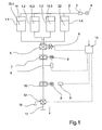
- Fig. 1 the construction of one of the first embodiment of the device according to the invention is shown schematically.
- the device has a plurality of tanks in a parallel arrangement next to each other.
- a total of four tanks 1.1, 1.2, 1.3 and 1.4 are shown.
- the tanks 1.1, 1.2 and 1.3 each contain a liquid substance, for example, a liquid paint in different designs.
- the liquid substance in the tank 1.1 by the reference numeral 15.1 in the tank 1.2 by the reference numeral 15.2 and in the tank 1.3 marked with the reference numeral 15.3.
- the tank 1.4 contains a rinsing agent 22, which is used as needed for rinsing the device becomes.
- the tanks 1.1 to 1.4 are pressure-tight and connected on their outlet side in each case via separate tank lines with a shuttle valve 5.
- the shuttle valve 5 is controllable via a pilot valve 6 such that one of the four ports is connected to a downstream primary pump 7.
- the primary pump 7 via the shuttle valve 5 can optionally connect to one of the tanks 1.1 to 1.4.
- the primary pump 7 is driven by an electric motor 8, which is controllable via a control unit 9.
- the control unit 9 is connected to a control device 13 which is likewise coupled via a control line to the pilot control valve 6 of the shuttle valve 5.
- the primary pump 7 For feeding the pumped by the primary pump 7 optionally from the tanks 1.1, 1.2 and 1.3 substance 15.1, 15.2 or 15.3, the primary pump 7 is directly downstream of a secondary pump 10.
- the secondary pump 10 is also driven by an electric motor 8, which is controllable via the control device 13 and the control unit 9.
- the secondary pump 10 conveys the substance directly in a feed line 17, which opens into a not shown here pickup system.
- Fig. 1 illustrated embodiment can be used for example advantageous for feeding liquid colors in a melt spinning process.
- the feed line 17 would open directly into a melt-carrying component, such as a melt line, a mixer or a spinning head.
- the exemplary embodiment is suitable for supplying any liquid substances to a dispensing system in metered form.
- a rinsing agent 22 is contained in the tank 1.4.
- the rinsing agent 22 can be conveyed directly by the control of the shuttle valve 5 via the primary pump 7 and the secondary pump 10 are supplied.
- the shuttle valve 5, the primary pump 7 and the secondary pump 10 can advantageously flush.
- a flushing valve 12 is arranged in the feed line 17, that is connected to a drain 18. By activating the flushing valve 12 via the control device 13, the flushing agent can thus be removed from the feed line 17 to a drain 18.
- the purge valve 12 can also be used advantageously together with one of the tanks 1.1 to 1.3 to first derive the new substance during a rinsing phase from the system after a change from one tank to another tank for the purpose of changing the substance.
- the tank 1.4 could be used to add another substance, e.g. B. to hold another color.
- FIG. 2 a further embodiment of the device according to the invention is shown schematically.
- the components of the same function are provided with identical reference numerals.
- Fig. 2 As shown in the technical environment of the invention, the same arrangement of tanks for holding a plurality of liquids is shown. It should be expressly mentioned at this point that the number of tanks in both the embodiment according to Fig. 1 as well as in the execution Fig. 2 are exemplary. Thus, a larger number of tanks can be integrated in the device according to the invention.
- the tanks 1.1 to 1.4 are assigned several shuttle valves and several secondary pumps. At the in Fig. 2 shown device a total of three shuttle valves 5.1, 5.2 and 5.3 are provided. Each of the shuttle valves 5.1, 5.2 and 5.3 have multiple ports to communicate with each of the tanks 1.1, 1.2, 1.3 and 1.4.
- the middle tanks 1.2 and 1.3 are each associated with only one connection of the shuttle valves 5.1, 5.2 and 5.3, since the tanks 1.2 and 1.3 can optionally be connected to the system via a switching valve 23.
- the switching valve 23 is controlled for this purpose via the control device 13.
- the substances 15.2 and 15.3 in the tanks 1.2 and 1.3 could be identical, so as to be able to hold a larger amount of a substance.
- the tank 1.4 serves to store a rinsing agent 22.
- the primary pump 7.1 can be connected to each of the tanks 1.1 to 1.4 via the shuttle valve 5.1.
- the primary pump 7.2 can be connected via the shuttle valve 5.2 with each of the tanks 1.1 to 1.4.
- the primary pump 7.3 via the shuttle valve 5.3 the tanks 1.1 to 1.4 can be selectively coupled.
- each pilot valves 6.1, 6.2 and 6.3 are assigned, which are coupled via control lines to the controller 13.
- the function and structure of the shuttle valves and the pilot valves are identical to the embodiment according to Fig. 1 , so that at this point no further explanation.
- the primary pumps 7.1, 7.2 and 7.3 are connected via a distribution system with a secondary pump 10.
- the distribution system is formed in this embodiment by the metering 20.1, 20.2 and 20.3, which connect the primary pumps 7.1, 7.2 and 7.3 with a manifold block 19.
- the distributor block 19 is connected to the secondary pump 10 via a collecting line 21.
- the secondary pump 10 is driven via the electric motor 8, which is controlled by the control device 13 and the control unit 9.
- a pressure sensor 11.1 is provided on the inlet side of the secondary pump 10 in the collecting line 21, which is directly coupled to the control device 13.
- a second pressure sensor 11.2 is provided between the secondary pump 10 and a mixing device 16 in the feed line 17, which is also coupled to the control device 13.
- the arranged on the outlet side of the secondary pump 10 in the feed line 17 mixing device 16 is formed in this embodiment as a static mixer.
- the mixing device 16 is formed by a dynamic mixer.
- the flush valve 12 On the outlet side of the mixing device 16, the flush valve 12 is arranged, which selectively connects the feed line 17 with a drain 18.
- the Purge valve 12 is also controlled via the control device 13 and could optionally interact with the tank 1.4 or one of the other tanks 1.1 to 1.3.
- Fig. 2 illustrated device is particularly suitable to supply a plurality of liquid substances such as liquid colors and mixtures between a pickup system with high flexibility.
- the use of the primary pumps 7.1 to 7.3 with different flow rates is particularly advantageous to produce exact dosages or mixing ratios between the liquid substances.
- a main component could be conveyed from the tank 1.3 via the changeover valve 23, the shuttle valve 5.3 and the primary pump 7.3.
- a second substance component could be conveyed to form a mixing ratio, for example from the tank 1.1 via the shuttle valve 5.1 by the primary pump 7.1 with low flow.
- the metered quantities of the primary pumps 7.1 and 7.3 are now supplied via the distribution system of the secondary pump 10.
- the secondary pump 10 conveys both substance components into the mixing device 16, in which the mixing of the substances 15.1 and 15.3 takes place. Subsequently, the substance mixture is supplied via the feed line 17 to a connected pickup system.
- the pickup system could, for example, be an extrusion system for melting a plastic melt. Thus, it would be advantageous to supply liquid additives to a plastic melt.
- the overpressure is detected in the collecting line 21 via the pressure sensor 11. 1 and monitored in the control device 13. As soon as a permissible upper value of the overpressure is exceeded, a corresponding control of the control unit 19 takes place, so that the electric motor 8 of the secondary pump 10 is driven at a higher speed. This increases the flow rate of the secondary pump 10, so that the pressure in the distribution system drops. In the event that the feed line 17 before the mixing device 16, an impermissible pressure increase occurs, this is detected by the pressure sensor 11.2 and monitored within the control device 13. If the pressure is exceeded, the system could be switched off accordingly.
- this can be the flushing agent 22 in the tank 1.4 selectively via the shuttle valves 5.1 to 5.3 and the primary pumps 7.1 to 7.3 promote. This makes it advantageous to perform a complete flushing of the material-carrying parts.
- the flushing agent is supplied to the drain 18 via the flushing valve 12. However, it is possible to carry out the rinsing with the newly selected substance.
- the apparatus shown can also be configured such that in each case a plurality of primary pumps with the same delivery rate are provided parallel to one another in order to selectively convey substances from a plurality of tanks. So it is also possible, the embodiment according to Fig. 2 to design with identical primary pumps.
- Fig. 1 and Fig. 2 shown shuttle valves for enabling the connections between the tanks and the primary pump is exemplary.
- the connections to the shuttle valve for connecting the tanks could also be switched separately by a plurality of sub-valves, which can be switched individually without pilot control directly via the control device.
- Fig. 3 is another device from the technical field of the invention shown schematically.
- each of the tanks 1.1 to 1.3 is assigned a primary pump 7.1 to 7.3 in each case.
- the tank 1.1 is directly connected to the primary pump 7.1
- the tank 1.2 is connected directly to the primary pump 7.2
- the tank 1.3 directly to the primary pump 7.3.
- the primary pumps 7.1, 7.2 and 7.3 are identical in their capacity.
- the primary pumps 7.1 to 7.3 are connected together with the secondary pump 10.
- the primary pumps 7.1 to 7.3 and the secondary pump 10 are each driven by an electric motor 8 and a control unit 9.
- the control devices 9 are coupled to the control device 13.
- the apparatus shown takes the removal of the substances 15.1, 15.2 or 15.3 from the tanks 1.1 to 1.3 directly through the primary pumps 7.1 to 7.3.
- the respective primary pump is activated via the control device 13, so that a metered amount of the respective substance of the secondary pump 10 is supplied.
- two primary pumps can be activated simultaneously to form mixtures, so that the respective metered quantity of two substances is led to a substance mixture.
- the one or more substances are guided via the secondary pump 10 in the mixing device 11 and then fed via the feed line 17 to the pickup system.
- Vorrichutngen shown are exemplary in the arrangement and structure of the individual components. In principle, variations and combinations of the embodiments shown are possible.
Landscapes
- Engineering & Computer Science (AREA)
- Mechanical Engineering (AREA)
- General Engineering & Computer Science (AREA)
- Textile Engineering (AREA)
- Physics & Mathematics (AREA)
- Fluid Mechanics (AREA)
- Processing And Handling Of Plastics And Other Materials For Molding In General (AREA)
- Glass Compositions (AREA)
- Electrically Driven Valve-Operating Means (AREA)
- Valve Device For Special Equipments (AREA)
- Feeding, Discharge, Calcimining, Fusing, And Gas-Generation Devices (AREA)
- Accessories For Mixers (AREA)
Claims (12)
- Dispositif destiné au dosage et à l'alimentation en substances liquides, notamment en couleurs liquides pour des fontes de matières plastiques avec une pluralité de tanks (1.1, 1.2) pour recevoir une pluralité de substances liquides (15.1, 15.2), avec au moins une pompe primaire (7) qui pour le prélèvement dosé d'une des substances (15.1, 15.2) est reliée avec au moins un des tanks (1.1, 1.2), et avec une pompe secondaire (10) qui est agencée en aval de la pompe primaire (7) et pour l'alimentation en substance (15.1, 15.2) est reliée avec une conduite d'alimentation (17), caractérisé en ce qu'une valve de changement de régime (5) est associée à la pompe primaire (7) sur le coté entrée et en ce que la valve de changement de régime (5) a une pluralité de connexions pour rattacher une pluralité de tanks (1.1. 1.2), les valves de changement de régime (5) pouvant être commandées de telle manière que la pompe primaire (7) peut être reliée au choix avec un des tanks connectés (1.1, 1.2).
- Dispositif selon la revendication 1, caractérisé en ce qu'une pluralité de pompes primaires (7.1, 7.2) et une pluralité de valves de changement de régime (5.1, 5.2) associées aux pompes primaires (7.1, 7.2) sont prévues, en ce que les valves de changement de régime (5.1, 5.2), associées aux pompes primaires (7.1, 7.2) ont respectivement une pluralité de connexions pour rattacher une pluralité de tanks (1.1, 1.2) et en ce que les valves de changement de régime (5.1, 5.2) peuvent être actionnées séparément.
- Dispositif selon la revendication 2, caractérisé en ce qu'une pluralité de soupapes pilotes (6.1, 6.2) pour commander les valves de changement de régime (5.1, 5.2) est prévue, lesquelles soupapes pilotes (6.1, 6.2) sont connectées avec une installation de commande (13) et lesquelles peuvent être commandées individuellement pour ajuster les valves de changement de régime (5.1, 5.2).
- Dispositif selon l'une des revendications 2 à 3, caractérisé en ce que les pompes primaires (7.1, 7.2) ont respectivement un moteur électrique (8) et un dispositif de commande (9) et en ce que les dispositifs de commande (9) sont connectés avec l'installation de commande (13).
- Dispositif selon l'une des revendications 2 à 4, caractérisé en ce que les pompes primaires (7.1, 7.2) sont réalisées en tant que pompes à engrenages avec des puissances de débit différentes, des pompes primaires individuelles (7.1, 7.2) ou un groupe de pompes primaires (7.1, 7.2) ayant respectivement une puissance de débit définie.
- Dispositif selon l'une des revendications 2 à 5,caractérisé en ce que les pompes primaires (7.1, 7.2) sont reliées communément à l'intermédiaire d'un système de distribution (20.1, 20.2, blo, 21) avec la pompe secondaire (10) et en ce que sur le coté sortie un dispositif de mélange (16) est associé à la pompe secondaire (10), lequel dispositif de mélange est relié à la conduite d'alimentation (17).
- Dispositif selon la revendication 6, caractérisé en ce que le système de distribution est doté d'une pluralité de conduites de dosage (20.1, 20.2) et d'au moins un bloc de distribution (19), les pompes primaires (7.1, 7.2) étant reliées à l'intermédiaire des conduites de dosage (20.1, 20.2) parallèlement avec le bloc de distribution (19) et le bloc de distribution (19) étant couplé à la pompe secondaire (10) par une conduite collectrice (21).
- Dispositif selon la revendication 6 ou 7, caractérisé en ce qu'un premier capteur de pression (11.1) est agencé dans la conduite collectrice (21) qui est relié à l'installation de commande (13) et en ce que la pompe secondaire (10) est entraînée par un moteur électrique (8), qui peut être commandé au moyen d'un dispositif de commande (9) par l'installation de commande (13).
- Dispositif selon l'une des revendications 6 à 8, caractérisé en ce qu'un deuxième capteur de pression (11.2) est agencé dans la conduite d'alimentation (17) entre la pompe secondaire (10) et le dispositif de mélange (16), lequel capteur de pression (11.2) est relié à l'installation de commande.
- Dispositif selon l'une des revendications 1 à 9, caractérisé en ce qu'une soupape de vidange (12) est agencée dans la conduite d'alimentation (17) par laquelle la conduite d'alimentation (17) peut être reliée à un égout (18).
- Dispositif selon la revendication 10, caractérisé en ce qu'un agent de rinçage (22) est contenu dans l'un des tanks (1.4).
- Dispositif selon l'une des revendications 1 à 11, caractérisé en ce que les tanks (1.1, 1.4) sont en connexion avec une source de pression (4) grâce à laquelle (4) un coussin à gaz (14) est respectivement généré dans les tanks, coussin à gaz (14) agissant sur la substance liquide.
Priority Applications (1)
| Application Number | Priority Date | Filing Date | Title |
|---|---|---|---|
| EP10191882A EP2292814B1 (fr) | 2007-09-13 | 2008-09-03 | Dispositif de dosage et d'alimentation de matières liquides |
Applications Claiming Priority (2)
| Application Number | Priority Date | Filing Date | Title |
|---|---|---|---|
| DE102007043711 | 2007-09-13 | ||
| PCT/EP2008/061641 WO2009037118A1 (fr) | 2007-09-13 | 2008-09-03 | Dispositif de dosage et d'injection de substances liquides |
Related Child Applications (1)
| Application Number | Title | Priority Date | Filing Date |
|---|---|---|---|
| EP10191882.9 Division-Into | 2010-11-19 |
Publications (2)
| Publication Number | Publication Date |
|---|---|
| EP2188420A1 EP2188420A1 (fr) | 2010-05-26 |
| EP2188420B1 true EP2188420B1 (fr) | 2011-02-23 |
Family
ID=39941458
Family Applications (2)
| Application Number | Title | Priority Date | Filing Date |
|---|---|---|---|
| EP10191882A Not-in-force EP2292814B1 (fr) | 2007-09-13 | 2008-09-03 | Dispositif de dosage et d'alimentation de matières liquides |
| EP08803612A Not-in-force EP2188420B1 (fr) | 2007-09-13 | 2008-09-03 | Dispositif de dosage et d'injection de substances liquides |
Family Applications Before (1)
| Application Number | Title | Priority Date | Filing Date |
|---|---|---|---|
| EP10191882A Not-in-force EP2292814B1 (fr) | 2007-09-13 | 2008-09-03 | Dispositif de dosage et d'alimentation de matières liquides |
Country Status (4)
| Country | Link |
|---|---|
| EP (2) | EP2292814B1 (fr) |
| AT (1) | ATE499463T1 (fr) |
| DE (1) | DE502008002691D1 (fr) |
| WO (1) | WO2009037118A1 (fr) |
Families Citing this family (12)
| Publication number | Priority date | Publication date | Assignee | Title |
|---|---|---|---|---|
| DE102010028786B4 (de) | 2009-05-11 | 2025-01-30 | Ineos Styrolution Europe Gmbh | Anlage und Verfahren zur kontinuierlichen Beschickung eines Extruders |
| DE102009045122A1 (de) * | 2009-09-29 | 2011-03-31 | Evonik Röhm Gmbh | Verfahren und Anlage zur Einfärbung von Kunststoffformmassen |
| ES2776130T3 (es) * | 2010-07-08 | 2020-07-29 | Colormatrix Holdings Inc | Procedimiento para el suministro de aditivos durante el procesamiento de plásticos |
| DE102011009426A1 (de) | 2011-01-26 | 2012-07-26 | Oerlikon Textile Gmbh & Co. Kg | Vorrichtung und Verfahren zum Dosieren und/oder Einspeisen flüssiger Farben und/oder Funktionsadditive |
| EP2634430B1 (fr) * | 2012-02-28 | 2018-08-08 | Maag Pump Systems AG | Ensemble formant pompe à engrenages |
| CN104451901B (zh) * | 2014-12-04 | 2017-03-01 | 郑州中远氨纶工程技术有限公司 | 计量装置及氨纶干法纺丝部件 |
| EP3666939B1 (fr) | 2018-12-12 | 2024-10-30 | Aladdin Manufacturing Corporation | Ensemble multifilament de filaments de polymeres fusionnes |
| DE102020100814A1 (de) * | 2020-01-15 | 2021-07-15 | Udo Tartler | Verfahren und Vorrichtung zum Mischen und Zuleiten von Kunststoff zur Vakuum-Infusion in eine Form |
| WO2021257738A1 (fr) | 2020-06-16 | 2021-12-23 | Aladdin Manufacturing Corporation | Systèmes et procédés de production d'un faisceau de filaments et/ou d'un fil |
| CN115836146B (zh) | 2020-06-16 | 2026-02-27 | 美国阿拉丁制造公司 | 用于提供颜色增强的纱线的系统和方法 |
| EP4164974A4 (fr) | 2020-06-16 | 2025-01-08 | Aladdin Manufacturing Corporation | Systèmes et procédés de production d'un faisceau de filaments et/ou d'un fil |
| CN117203383A (zh) | 2021-04-23 | 2023-12-08 | 美国阿拉丁制造公司 | 制造纱线的方法和以该方式获得的纱线 |
Family Cites Families (5)
| Publication number | Priority date | Publication date | Assignee | Title |
|---|---|---|---|---|
| JPH07112708B2 (ja) | 1991-05-02 | 1995-12-06 | ワイケイケイ株式会社 | 射出成形機における着色成形材料の自動変換供給装置 |
| DE69735865T2 (de) * | 1996-03-04 | 2006-11-16 | Honeywell International Inc. | Verfahren zur Herstellung von Additiven für synthetische Filamente und Einarbeitung dieser Additive in thermoplastische filamentbildende Polymermaterialien |
| US6572803B1 (en) * | 1999-09-21 | 2003-06-03 | Burke Mills, Inc. | Liquid color feed system for synthetic yarns |
| DE10233468A1 (de) * | 2002-07-24 | 2004-02-12 | Barmag Ag | Vorrichtung und Verfahren zum Einspeisen einer flüssigen Farbe in eine Polymerschmelze |
| EP1692328A1 (fr) * | 2003-12-12 | 2006-08-23 | Saurer GmbH & Co. KG | Dispositif de dosage permettant l'alimentation haute pression en additif liquide |
-
2008
- 2008-09-03 EP EP10191882A patent/EP2292814B1/fr not_active Not-in-force
- 2008-09-03 AT AT08803612T patent/ATE499463T1/de active
- 2008-09-03 DE DE502008002691T patent/DE502008002691D1/de active Active
- 2008-09-03 EP EP08803612A patent/EP2188420B1/fr not_active Not-in-force
- 2008-09-03 WO PCT/EP2008/061641 patent/WO2009037118A1/fr not_active Ceased
Also Published As
| Publication number | Publication date |
|---|---|
| EP2188420A1 (fr) | 2010-05-26 |
| WO2009037118A1 (fr) | 2009-03-26 |
| ATE499463T1 (de) | 2011-03-15 |
| EP2292814B1 (fr) | 2013-01-30 |
| DE502008002691D1 (de) | 2011-04-07 |
| EP2292814A1 (fr) | 2011-03-09 |
Similar Documents
| Publication | Publication Date | Title |
|---|---|---|
| EP2188420B1 (fr) | Dispositif de dosage et d'injection de substances liquides | |
| EP1558796B1 (fr) | Dispositif et procede destines a alimenter une peinture liquide dans une fusion polymere | |
| EP0024330B1 (fr) | Procédé pour la fabrication de pièces en un mélange réactionnel à plusieurs composants | |
| DE2417865C2 (de) | Vorrichtung zum Extrudieren von Kunststoff | |
| DE60019480T2 (de) | Einspritzventil zur Verbesserung von der Farbdosierungsreaktionszeit | |
| EP2668012A1 (fr) | Dispositif et procédé de dosage et/ou d'injection de colorants liquides et/ou d'additifs fonctionnels | |
| EP1943009A1 (fr) | Dispositif et procede pour melanger un colorant liquide et procede pour colorer des matieres plastiques au moyen d'un colorant liquide | |
| EP0636190B1 (fr) | Installation de filage de fils thermoplastiques | |
| EP2158041B1 (fr) | Système microfluidique pour mélanger au moins deux substances de départ | |
| DE10223374B4 (de) | Vorrichtung zum universellen Einfärben von kontinuierlich unter Druck strömenden, in einer Plastifiziereinheit plastifizierten viskosen Massen | |
| DE102022106334A1 (de) | Filtriervorrichtung zum Filtrieren eines Fluids sowie betreffendes Betriebsverfahren | |
| DE102015224490A1 (de) | Vorrichtung zum Pudern von Druckbogen | |
| DE102007056594B4 (de) | Siebwechsler | |
| DE202017100255U1 (de) | Vorrichtung zur Herstellung von faserverstärkten Kunststoff-Formteilen | |
| EP1011852A1 (fr) | Procede et dispositif pour melanger des fluides dans une conduite | |
| EP0332982B1 (fr) | Procédé et dispositif pour mélanger des matières plastiques à plusieurs composants, en particulier le polyuréthane | |
| EP4311642B1 (fr) | Dispositif de fourniture d'une matière plastique, ainsi que procédé associé de dosage de la matière plastique | |
| DE10314117B3 (de) | Mischkopf für eine Reaktionsgießmaschine | |
| DE102006055278B3 (de) | Reinigungsverfahren sowie Reinigungsvorrichtung für eine Zylinderoberfläche einer Druckmaschine | |
| EP4397467A1 (fr) | Procédé et dispositif pour la production continue de mousse de polyuréthane en bloc | |
| AT11732U1 (de) | Verfahren zur herstellung von spritzgiessformteilen, die aus einer mischung von wenigstens zwei kunststoffmassen bestehen | |
| DE20321049U1 (de) | Vorrichtung zum Filtrieren eines Fluids, insbesondere für kunststoffverarbeitende Anlagen | |
| EP3560580A1 (fr) | Installation et procédé de fabrication d'un mélange de bitume | |
| DD155504A1 (de) | Statische mischvorrichtung fuer spritzgiessmaschinen und extruder | |
| DE202005020880U1 (de) | Zuschlagsstoff-Zufuhrvorrichtung für Mischkopf und Mischkopfsystem mit solcher Zufuhrvorrichtung |
Legal Events
| Date | Code | Title | Description |
|---|---|---|---|
| PUAI | Public reference made under article 153(3) epc to a published international application that has entered the european phase |
Free format text: ORIGINAL CODE: 0009012 |
|
| 17P | Request for examination filed |
Effective date: 20100204 |
|
| AK | Designated contracting states |
Kind code of ref document: A1 Designated state(s): AT BE BG CH CY CZ DE DK EE ES FI FR GB GR HR HU IE IS IT LI LT LU LV MC MT NL NO PL PT RO SE SI SK TR |
|
| AX | Request for extension of the european patent |
Extension state: AL BA MK RS |
|
| GRAP | Despatch of communication of intention to grant a patent |
Free format text: ORIGINAL CODE: EPIDOSNIGR1 |
|
| DAX | Request for extension of the european patent (deleted) | ||
| GRAS | Grant fee paid |
Free format text: ORIGINAL CODE: EPIDOSNIGR3 |
|
| GRAA | (expected) grant |
Free format text: ORIGINAL CODE: 0009210 |
|
| AK | Designated contracting states |
Kind code of ref document: B1 Designated state(s): AT BE BG CH CY CZ DE DK EE ES FI FR GB GR HR HU IE IS IT LI LT LU LV MC MT NL NO PL PT RO SE SI SK TR |
|
| REG | Reference to a national code |
Ref country code: GB Ref legal event code: FG4D Free format text: NOT ENGLISH |
|
| REG | Reference to a national code |
Ref country code: CH Ref legal event code: EP |
|
| REG | Reference to a national code |
Ref country code: IE Ref legal event code: FG4D Free format text: LANGUAGE OF EP DOCUMENT: GERMAN |
|
| REF | Corresponds to: |
Ref document number: 502008002691 Country of ref document: DE Date of ref document: 20110407 Kind code of ref document: P |
|
| REG | Reference to a national code |
Ref country code: DE Ref legal event code: R096 Ref document number: 502008002691 Country of ref document: DE Effective date: 20110407 |
|
| REG | Reference to a national code |
Ref country code: NL Ref legal event code: VDEP Effective date: 20110223 |
|
| LTIE | Lt: invalidation of european patent or patent extension |
Effective date: 20110223 |
|
| PG25 | Lapsed in a contracting state [announced via postgrant information from national office to epo] |
Ref country code: LT Free format text: LAPSE BECAUSE OF FAILURE TO SUBMIT A TRANSLATION OF THE DESCRIPTION OR TO PAY THE FEE WITHIN THE PRESCRIBED TIME-LIMIT Effective date: 20110223 Ref country code: SE Free format text: LAPSE BECAUSE OF FAILURE TO SUBMIT A TRANSLATION OF THE DESCRIPTION OR TO PAY THE FEE WITHIN THE PRESCRIBED TIME-LIMIT Effective date: 20110223 Ref country code: GR Free format text: LAPSE BECAUSE OF FAILURE TO SUBMIT A TRANSLATION OF THE DESCRIPTION OR TO PAY THE FEE WITHIN THE PRESCRIBED TIME-LIMIT Effective date: 20110524 Ref country code: HR Free format text: LAPSE BECAUSE OF FAILURE TO SUBMIT A TRANSLATION OF THE DESCRIPTION OR TO PAY THE FEE WITHIN THE PRESCRIBED TIME-LIMIT Effective date: 20110223 Ref country code: NO Free format text: LAPSE BECAUSE OF FAILURE TO SUBMIT A TRANSLATION OF THE DESCRIPTION OR TO PAY THE FEE WITHIN THE PRESCRIBED TIME-LIMIT Effective date: 20110523 Ref country code: LV Free format text: LAPSE BECAUSE OF FAILURE TO SUBMIT A TRANSLATION OF THE DESCRIPTION OR TO PAY THE FEE WITHIN THE PRESCRIBED TIME-LIMIT Effective date: 20110223 Ref country code: ES Free format text: LAPSE BECAUSE OF FAILURE TO SUBMIT A TRANSLATION OF THE DESCRIPTION OR TO PAY THE FEE WITHIN THE PRESCRIBED TIME-LIMIT Effective date: 20110603 Ref country code: PT Free format text: LAPSE BECAUSE OF FAILURE TO SUBMIT A TRANSLATION OF THE DESCRIPTION OR TO PAY THE FEE WITHIN THE PRESCRIBED TIME-LIMIT Effective date: 20110623 |
|
| PG25 | Lapsed in a contracting state [announced via postgrant information from national office to epo] |
Ref country code: CY Free format text: LAPSE BECAUSE OF FAILURE TO SUBMIT A TRANSLATION OF THE DESCRIPTION OR TO PAY THE FEE WITHIN THE PRESCRIBED TIME-LIMIT Effective date: 20110223 Ref country code: NL Free format text: LAPSE BECAUSE OF FAILURE TO SUBMIT A TRANSLATION OF THE DESCRIPTION OR TO PAY THE FEE WITHIN THE PRESCRIBED TIME-LIMIT Effective date: 20110223 Ref country code: SI Free format text: LAPSE BECAUSE OF FAILURE TO SUBMIT A TRANSLATION OF THE DESCRIPTION OR TO PAY THE FEE WITHIN THE PRESCRIBED TIME-LIMIT Effective date: 20110223 Ref country code: FI Free format text: LAPSE BECAUSE OF FAILURE TO SUBMIT A TRANSLATION OF THE DESCRIPTION OR TO PAY THE FEE WITHIN THE PRESCRIBED TIME-LIMIT Effective date: 20110223 Ref country code: BG Free format text: LAPSE BECAUSE OF FAILURE TO SUBMIT A TRANSLATION OF THE DESCRIPTION OR TO PAY THE FEE WITHIN THE PRESCRIBED TIME-LIMIT Effective date: 20110523 |
|
| REG | Reference to a national code |
Ref country code: IE Ref legal event code: FD4D |
|
| PG25 | Lapsed in a contracting state [announced via postgrant information from national office to epo] |
Ref country code: DK Free format text: LAPSE BECAUSE OF FAILURE TO SUBMIT A TRANSLATION OF THE DESCRIPTION OR TO PAY THE FEE WITHIN THE PRESCRIBED TIME-LIMIT Effective date: 20110223 Ref country code: IE Free format text: LAPSE BECAUSE OF FAILURE TO SUBMIT A TRANSLATION OF THE DESCRIPTION OR TO PAY THE FEE WITHIN THE PRESCRIBED TIME-LIMIT Effective date: 20110223 Ref country code: EE Free format text: LAPSE BECAUSE OF FAILURE TO SUBMIT A TRANSLATION OF THE DESCRIPTION OR TO PAY THE FEE WITHIN THE PRESCRIBED TIME-LIMIT Effective date: 20110223 |
|
| PG25 | Lapsed in a contracting state [announced via postgrant information from national office to epo] |
Ref country code: SK Free format text: LAPSE BECAUSE OF FAILURE TO SUBMIT A TRANSLATION OF THE DESCRIPTION OR TO PAY THE FEE WITHIN THE PRESCRIBED TIME-LIMIT Effective date: 20110223 Ref country code: RO Free format text: LAPSE BECAUSE OF FAILURE TO SUBMIT A TRANSLATION OF THE DESCRIPTION OR TO PAY THE FEE WITHIN THE PRESCRIBED TIME-LIMIT Effective date: 20110223 Ref country code: CZ Free format text: LAPSE BECAUSE OF FAILURE TO SUBMIT A TRANSLATION OF THE DESCRIPTION OR TO PAY THE FEE WITHIN THE PRESCRIBED TIME-LIMIT Effective date: 20110223 |
|
| PLBE | No opposition filed within time limit |
Free format text: ORIGINAL CODE: 0009261 |
|
| STAA | Information on the status of an ep patent application or granted ep patent |
Free format text: STATUS: NO OPPOSITION FILED WITHIN TIME LIMIT |
|
| 26N | No opposition filed |
Effective date: 20111124 |
|
| PG25 | Lapsed in a contracting state [announced via postgrant information from national office to epo] |
Ref country code: PL Free format text: LAPSE BECAUSE OF FAILURE TO SUBMIT A TRANSLATION OF THE DESCRIPTION OR TO PAY THE FEE WITHIN THE PRESCRIBED TIME-LIMIT Effective date: 20110223 |
|
| REG | Reference to a national code |
Ref country code: DE Ref legal event code: R097 Ref document number: 502008002691 Country of ref document: DE Effective date: 20111124 |
|
| BERE | Be: lapsed |
Owner name: OERLIKON TEXTILE G.M.B.H. & CO. KG Effective date: 20110930 |
|
| PG25 | Lapsed in a contracting state [announced via postgrant information from national office to epo] |
Ref country code: MC Free format text: LAPSE BECAUSE OF NON-PAYMENT OF DUE FEES Effective date: 20110930 |
|
| PG25 | Lapsed in a contracting state [announced via postgrant information from national office to epo] |
Ref country code: IT Free format text: LAPSE BECAUSE OF FAILURE TO SUBMIT A TRANSLATION OF THE DESCRIPTION OR TO PAY THE FEE WITHIN THE PRESCRIBED TIME-LIMIT Effective date: 20110223 |
|
| REG | Reference to a national code |
Ref country code: FR Ref legal event code: ST Effective date: 20120531 |
|
| PG25 | Lapsed in a contracting state [announced via postgrant information from national office to epo] |
Ref country code: BE Free format text: LAPSE BECAUSE OF NON-PAYMENT OF DUE FEES Effective date: 20110930 |
|
| PG25 | Lapsed in a contracting state [announced via postgrant information from national office to epo] |
Ref country code: FR Free format text: LAPSE BECAUSE OF NON-PAYMENT OF DUE FEES Effective date: 20110930 |
|
| PG25 | Lapsed in a contracting state [announced via postgrant information from national office to epo] |
Ref country code: MT Free format text: LAPSE BECAUSE OF FAILURE TO SUBMIT A TRANSLATION OF THE DESCRIPTION OR TO PAY THE FEE WITHIN THE PRESCRIBED TIME-LIMIT Effective date: 20110223 |
|
| REG | Reference to a national code |
Ref country code: CH Ref legal event code: PL |
|
| GBPC | Gb: european patent ceased through non-payment of renewal fee |
Effective date: 20120903 |
|
| PG25 | Lapsed in a contracting state [announced via postgrant information from national office to epo] |
Ref country code: LU Free format text: LAPSE BECAUSE OF NON-PAYMENT OF DUE FEES Effective date: 20110903 |
|
| PG25 | Lapsed in a contracting state [announced via postgrant information from national office to epo] |
Ref country code: LI Free format text: LAPSE BECAUSE OF NON-PAYMENT OF DUE FEES Effective date: 20120930 Ref country code: GB Free format text: LAPSE BECAUSE OF NON-PAYMENT OF DUE FEES Effective date: 20120903 Ref country code: IS Free format text: LAPSE BECAUSE OF FAILURE TO SUBMIT A TRANSLATION OF THE DESCRIPTION OR TO PAY THE FEE WITHIN THE PRESCRIBED TIME-LIMIT Effective date: 20110223 Ref country code: CH Free format text: LAPSE BECAUSE OF NON-PAYMENT OF DUE FEES Effective date: 20120930 |
|
| PG25 | Lapsed in a contracting state [announced via postgrant information from national office to epo] |
Ref country code: TR Free format text: LAPSE BECAUSE OF FAILURE TO SUBMIT A TRANSLATION OF THE DESCRIPTION OR TO PAY THE FEE WITHIN THE PRESCRIBED TIME-LIMIT Effective date: 20110223 |
|
| PG25 | Lapsed in a contracting state [announced via postgrant information from national office to epo] |
Ref country code: HU Free format text: LAPSE BECAUSE OF FAILURE TO SUBMIT A TRANSLATION OF THE DESCRIPTION OR TO PAY THE FEE WITHIN THE PRESCRIBED TIME-LIMIT Effective date: 20110223 |
|
| REG | Reference to a national code |
Ref country code: AT Ref legal event code: MM01 Ref document number: 499463 Country of ref document: AT Kind code of ref document: T Effective date: 20130903 |
|
| PG25 | Lapsed in a contracting state [announced via postgrant information from national office to epo] |
Ref country code: AT Free format text: LAPSE BECAUSE OF NON-PAYMENT OF DUE FEES Effective date: 20130903 |
|
| PGFP | Annual fee paid to national office [announced via postgrant information from national office to epo] |
Ref country code: DE Payment date: 20230920 Year of fee payment: 16 |
|
| REG | Reference to a national code |
Ref country code: DE Ref legal event code: R119 Ref document number: 502008002691 Country of ref document: DE |
|
| PG25 | Lapsed in a contracting state [announced via postgrant information from national office to epo] |
Ref country code: DE Free format text: LAPSE BECAUSE OF NON-PAYMENT OF DUE FEES Effective date: 20250401 |