EP2188541B1 - Procede et palier de montage d'appareils rotatifs, notamment d'un scanner medical - Google Patents
Procede et palier de montage d'appareils rotatifs, notamment d'un scanner medical Download PDFInfo
- Publication number
- EP2188541B1 EP2188541B1 EP08785520A EP08785520A EP2188541B1 EP 2188541 B1 EP2188541 B1 EP 2188541B1 EP 08785520 A EP08785520 A EP 08785520A EP 08785520 A EP08785520 A EP 08785520A EP 2188541 B1 EP2188541 B1 EP 2188541B1
- Authority
- EP
- European Patent Office
- Prior art keywords
- bearing
- electromagnets
- outer ring
- inner ring
- ring
- Prior art date
- Legal status (The legal status is an assumption and is not a legal conclusion. Google has not performed a legal analysis and makes no representation as to the accuracy of the status listed.)
- Not-in-force
Links
- 238000000034 method Methods 0.000 title abstract description 4
- 229910000906 Bronze Inorganic materials 0.000 claims description 2
- 239000010974 bronze Substances 0.000 claims description 2
- KUNSUQLRTQLHQQ-UHFFFAOYSA-N copper tin Chemical compound [Cu].[Sn] KUNSUQLRTQLHQQ-UHFFFAOYSA-N 0.000 claims description 2
- 239000007788 liquid Substances 0.000 claims 1
- 229920002994 synthetic fiber Polymers 0.000 claims 1
- XLYOFNOQVPJJNP-UHFFFAOYSA-N water Substances O XLYOFNOQVPJJNP-UHFFFAOYSA-N 0.000 claims 1
- 238000005096 rolling process Methods 0.000 description 9
- 238000006243 chemical reaction Methods 0.000 description 2
- 238000010276 construction Methods 0.000 description 2
- 230000001965 increasing effect Effects 0.000 description 2
- 239000000463 material Substances 0.000 description 2
- 238000005259 measurement Methods 0.000 description 2
- 238000006073 displacement reaction Methods 0.000 description 1
- 229920001971 elastomer Polymers 0.000 description 1
- 239000000806 elastomer Substances 0.000 description 1
- 230000005284 excitation Effects 0.000 description 1
- 210000003746 feather Anatomy 0.000 description 1
- 230000001939 inductive effect Effects 0.000 description 1
- 238000002955 isolation Methods 0.000 description 1
- 230000003287 optical effect Effects 0.000 description 1
- 230000002093 peripheral effect Effects 0.000 description 1
Images


Classifications
-
- F—MECHANICAL ENGINEERING; LIGHTING; HEATING; WEAPONS; BLASTING
- F16—ENGINEERING ELEMENTS AND UNITS; GENERAL MEASURES FOR PRODUCING AND MAINTAINING EFFECTIVE FUNCTIONING OF MACHINES OR INSTALLATIONS; THERMAL INSULATION IN GENERAL
- F16C—SHAFTS; FLEXIBLE SHAFTS; ELEMENTS OR CRANKSHAFT MECHANISMS; ROTARY BODIES OTHER THAN GEARING ELEMENTS; BEARINGS
- F16C33/00—Parts of bearings; Special methods for making bearings or parts thereof
- F16C33/30—Parts of ball or roller bearings
- F16C33/38—Ball cages
-
- F—MECHANICAL ENGINEERING; LIGHTING; HEATING; WEAPONS; BLASTING
- F16—ENGINEERING ELEMENTS AND UNITS; GENERAL MEASURES FOR PRODUCING AND MAINTAINING EFFECTIVE FUNCTIONING OF MACHINES OR INSTALLATIONS; THERMAL INSULATION IN GENERAL
- F16C—SHAFTS; FLEXIBLE SHAFTS; ELEMENTS OR CRANKSHAFT MECHANISMS; ROTARY BODIES OTHER THAN GEARING ELEMENTS; BEARINGS
- F16C32/00—Bearings not otherwise provided for
- F16C32/04—Bearings not otherwise provided for using magnetic or electric supporting means
- F16C32/0406—Magnetic bearings
- F16C32/044—Active magnetic bearings
- F16C32/0442—Active magnetic bearings with devices affected by abnormal, undesired or non-standard conditions such as shock-load, power outage, start-up or touchdown
-
- F—MECHANICAL ENGINEERING; LIGHTING; HEATING; WEAPONS; BLASTING
- F16—ENGINEERING ELEMENTS AND UNITS; GENERAL MEASURES FOR PRODUCING AND MAINTAINING EFFECTIVE FUNCTIONING OF MACHINES OR INSTALLATIONS; THERMAL INSULATION IN GENERAL
- F16C—SHAFTS; FLEXIBLE SHAFTS; ELEMENTS OR CRANKSHAFT MECHANISMS; ROTARY BODIES OTHER THAN GEARING ELEMENTS; BEARINGS
- F16C32/00—Bearings not otherwise provided for
- F16C32/04—Bearings not otherwise provided for using magnetic or electric supporting means
- F16C32/0406—Magnetic bearings
- F16C32/044—Active magnetic bearings
- F16C32/0474—Active magnetic bearings for rotary movement
- F16C32/0493—Active magnetic bearings for rotary movement integrated in an electrodynamic machine, e.g. self-bearing motor
-
- F—MECHANICAL ENGINEERING; LIGHTING; HEATING; WEAPONS; BLASTING
- F16—ENGINEERING ELEMENTS AND UNITS; GENERAL MEASURES FOR PRODUCING AND MAINTAINING EFFECTIVE FUNCTIONING OF MACHINES OR INSTALLATIONS; THERMAL INSULATION IN GENERAL
- F16C—SHAFTS; FLEXIBLE SHAFTS; ELEMENTS OR CRANKSHAFT MECHANISMS; ROTARY BODIES OTHER THAN GEARING ELEMENTS; BEARINGS
- F16C39/00—Relieving load on bearings
- F16C39/02—Relieving load on bearings using mechanical means
-
- F—MECHANICAL ENGINEERING; LIGHTING; HEATING; WEAPONS; BLASTING
- F16—ENGINEERING ELEMENTS AND UNITS; GENERAL MEASURES FOR PRODUCING AND MAINTAINING EFFECTIVE FUNCTIONING OF MACHINES OR INSTALLATIONS; THERMAL INSULATION IN GENERAL
- F16C—SHAFTS; FLEXIBLE SHAFTS; ELEMENTS OR CRANKSHAFT MECHANISMS; ROTARY BODIES OTHER THAN GEARING ELEMENTS; BEARINGS
- F16C2300/00—Application independent of particular apparatuses
- F16C2300/10—Application independent of particular apparatuses related to size
- F16C2300/14—Large applications, e.g. bearings having an inner diameter exceeding 500 mm
-
- F—MECHANICAL ENGINEERING; LIGHTING; HEATING; WEAPONS; BLASTING
- F16—ENGINEERING ELEMENTS AND UNITS; GENERAL MEASURES FOR PRODUCING AND MAINTAINING EFFECTIVE FUNCTIONING OF MACHINES OR INSTALLATIONS; THERMAL INSULATION IN GENERAL
- F16C—SHAFTS; FLEXIBLE SHAFTS; ELEMENTS OR CRANKSHAFT MECHANISMS; ROTARY BODIES OTHER THAN GEARING ELEMENTS; BEARINGS
- F16C2316/00—Apparatus in health or amusement
- F16C2316/10—Apparatus in health or amusement in medical appliances, e.g. in diagnosis, dentistry, instruments, prostheses, medical imaging appliances
Definitions
- the invention relates to a bearing for mounting rotatable devices, in particular a medical scanner with at least one inner ring and at least one outer ring according to the preamble of the independent claims.
- the main source of noise when operating a scanner is the rolling bearing, which continuously generates structure-borne noise by means of a permanent circulation (rolling contact) of the rolling elements and transmits it to the connecting structures which emit it as airborne sound (noise).
- the invention is therefore based on the object to propose a bearing for such devices, in which the noise emission can be further reduced and in particular a sufficient protection of the bearing is given in case of power failure.
- a large rolling bearing in which the stationary ring is separated from the rotating ring by the magnetic field of a plurality of electromagnets, so that there is no metallic contact between the two bearing rings during operation.
- the electromagnets are arranged both in the axial and radial direction of the bearing axis to accommodate the bearing forces and moments to be supported.
- the distribution of the electromagnets over the bearing circumference may be uniform or adapted to the load.
- the bearing further contains optical or inductive distance sensors, which measure the gap distance between the outer and inner ring preferably optically, inductively or in any other way and / or control. A computer-controlled control of the magnets is carried out so that the gap distance is kept constant.
- a fishing camp is further provided, which carries the rotating ring in the event that the power supply of the electromagnets fails. This fishing camp can be designed as sliding or rolling bearings.
- the electromagnets can also be used to vary the rigidity of the bearing and to avoid vibrations. By increasing the current and thus the force in the electromagnet, the rigidity can be increased specifically. In this way, in particular, the natural frequency of the bearing can be changed and thus resonance frequencies can be avoided. It has In addition, it was found that the redundancy of distance sensors and electromagnets reduces the probability of failure Magnetic bearing can be reduced so far that under certain circumstances can even be dispensed with the fishing camp.
- the electromagnets and the distance sensors can also be used, in particular during the first start-up, to balance the bearing.
- For balancing is usually one or more times an imbalance with known mass, known center distance and known circumferential position attached to the rotor.
- the reaction for.
- the location and the additional mass which must be attached to the rotor to operate the rotor without imbalance.
- the bearing according to the invention can now be applied with the aid of electromagnets, a circumferential force corresponding to the known mass with known center distance and location on the rotor.
- the reaction of the rotor at constant speed can then be measured by the distance sensors. These measurements are then used in operation with certain circumferential force to select the additional mass and their mounting location.
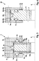
- the outer ring 2 is formed as a stator, wherein in the individual outer rings 2a and 2c, the electromagnets 3a and the outer ring 2b, the electromagnets 3b are arranged, which are opposite to the two axial surfaces and the radial surface of the inner ring serving as a rotor 1.
- inner ring 1 and outer ring 2 are kept at a uniform distance from each other during rotation about the common axis of rotation 8, so that there is no metallic contact between the two bearing rings during operation.
- distance sensors 4a, 4b are respectively provided in the vicinity of the electromagnets 3a, 3b.
- the fishing camps 5a - 5e are either attached to the outer ring 2, 12, 20 or on the inner ring 1, 10, 11 and have in normal operation a small distance from the opposite surface. In case of failure of the power supply for the electromagnets 3a, 3b, these fishing camp 5a - 5e can carry the respective rotating ring.
- the holes 6 and 7 are used to attach the respective ring to the connection structures, not shown.
- the inner ring 11 is formed as a stator on which the electromagnets 13a, 13b are arranged.
- the outer ring 12 encloses with the individual rings 12a, 12b U-shaped the outer end of the inner ring 11, wherein the fishing camp 5a, 5c and the distance sensors 4a, 4b are arranged in the same way between the two rings 11 and 12.
- the inner ring 10 is formed in several parts, wherein between the two magnetic inner rings 10a, 10c, an amagnetic inner ring 10b is arranged. On the outer circumference of this inner ring 10b can act as a sliding element relative to the fishing camp 5e, being used as a sliding bearing material plastic or bronze.
- the outer ring 20 is formed in several parts, wherein between the magnetic outer rings 20a and 20c, the non-magnetic outer ring 20b is located.
- the nonmagnetic rings 10b, 20b are used for magnetic isolation between the adjacent rings 10a, 10c and 20a, 20c.
- the non-magnetic outer ring 20b can be used as sliding elements relative to the fishing camp 5d.
- Fig. 5 is an enlarged view of the arrangement of a ball bearing with balls to see 9, wherein the balls are circumferentially guided in a cage 21. With the help of the spring 22, a prestressed cage 21 is present. This has the advantage that it is ensured that the retainer bearing 5c designed as a rolling bearing is only moved when the retainer bearing 5c is actually loaded. In this case, the use of a ball bearing in the execution after Fig. 2 can be waived there on the fishing camp 5a. It is also important that between the outer ring 12b and the balls 9, a distance 23 is maintained in the normal operating condition of the bearing. If contact occurs in this area, the ball bearing prevents excessive friction.
Landscapes
- Engineering & Computer Science (AREA)
- General Engineering & Computer Science (AREA)
- Mechanical Engineering (AREA)
- Rolling Contact Bearings (AREA)
- Magnetic Bearings And Hydrostatic Bearings (AREA)
Claims (9)
- Palier pour le montage d'appareils rotatifs, en particulier d'un scanner médical avec une bague intérieure (1, 11) et une bague extérieure (2, 12), sachant que- la bague intérieure (1, 11) et la bague extérieure (2, 12) sont guidées, sans contact, à travers le champ magnétique d'électroaimants (3a, 3b), en direction axiale et /ou en direction radiale,- l'intervalle entre elles est contrôlé et commandé à l'aide de détecteurs de distance (4a, 4b),- la bague extérieure (2, 12) est exécutée en plusieurs pièces et présente, à l'état assemblé, une section transversale en U, ouverte vers l'intérieur,- la bague intérieure (1, 11) fait saillie à l'intérieur de la bague extérieure (2, 12),- dans chacune des sections de la bague intérieure (1, 11) ou de la bague extérieure (2, 12), opposées axialement ou radialement, sont agencés des électroaimants (3a, 3b) et des détecteurs de distance (4a, 4b),caractérisé en ce que- à côté ou dans la région de chacun des électroaimants (3a, 3b), est disposé au moins un palier d'arrêt (5a, 5b, 5c, 5d, 5e), qui porte la bague rotative en cas de manque de courant d'alimentation des électroaimants (3a, 3b), et- au moins l'un des paliers d'arrêt (5c) est réalisé sous la forme d'un palier à roulement radial, qui, doté de billes (9) ou de rouleaux, maintenus dans une cage (21) précontrainte par au moins un ressort (2), est disposé entre les sections de la bague intérieure (1, 11) et de la bague extérieure (2, 12) radialement opposées.
- Palier pour le montage d'appareils rotatifs, en particulier d'un scanner médical avec une bague intérieure (10) et une bague extérieure (20), sachant que- la bague intérieure (10) et la bague extérieure (20) sont guidées, sans contact, à travers le champ magnétique d'électroaimants (3a, 3b), en direction axiale et / ou en direction radiale,- l'intervalle entre elles est contrôlé et commandé à l'aide de détecteurs de distance (4a, 4b),- la bague extérieure (20) est exécutée en plusieurs pièces et présente, à l'état assemblé, une section transversale en U, ouverte vers l'intérieur,- la bague intérieure (10) fait saillie à l'intérieur de la bague extérieure (20),- dans chacune des sections de la bague intérieure (10) ou de la bague extérieure (20), opposées axialement ou radialement, sont agencés des électroaimants (3a, 3b) et des détecteurs de distance (4a, 4b),caractérisé en ce que- à côté ou dans la région de chacun des électroaimants (3a, 3b), est disposé au moins un palier d'arrêt (5a, 5b, 5c, 5d, 5e), qui porte la bague rotative en cas de manque de courant d'alimentation des électroaimants (3a, 3b), et- au moins l'un des paliers d'arrêt (5d, 5e) est réalisé sous la forme d'un palier à roulement radial, et que- la bague intérieure (10) ou la bague extérieure (20), ne portant pas d'électroaimants (3a, 3b) consiste en plusieurs bagues magnétiques (10a, 10c, 20a, 20c), qui sont séparées les unes des autres par des bagues amagnétiques (10b, 20b), et que les bagues amagnétiques (10b, 20b) servent d'éléments de glissement du palier d'arrêt (5d, 5e), qui est réalisé sous la forme d'un palier de roulement radial.
- Palier selon revendication 1 ou 2, caractérisé en ce que les électroaimants (3a, 3b) sont disposés soit dans la bague extérieure (2) soit dans la bague intérieure (11), dans des évidements ouverts vers la bague opposée.
- Palier selon revendication 1 ou 3, caractérisé en ce que sont disposés, à côté ou dans la région de chacun des électroaimants (3a, 3b), un ou plusieurs détecteurs de distance (4a, 4b), qui fonctionnent de manière optique, inductive ou de manière similaire.
- Palier selon revendication 1 ou 2, caractérisé en ce que les détecteurs de distance (4a, 4b) et les électroaimants (3a, 3b) sont installés de manière redondante dans le palier.
- Palier selon revendication 1 ou 2, caractérisé en ce que les détecteurs de distance (4a, 4b) et les électroaimants (3a, 3b) ainsi que la commande sont reliés à un système d'alimentation en courant exempte d'interruptions.
- Palier selon revendication 1 ou 2, caractérisé en ce que la bague extérieure (2, 12, 20) est pourvue, sur son diamètre extérieur, de moyens de prise pour une courroie dentée ou trapézoïdale.
- Palier selon revendication 1 ou 2, caractérisé en ce que les détecteurs de distance (4a, 4b) et les électroaimants (3a, 3b) sont incorporés de manière protégée et sont formés de sorte que le palier puisse être aussi utilisé dans des média liquides, en particulier dans de l'eau.
- Palier selon la revendication 2, caractérisé en ce que les bagues magnétiques sont en matière synthétique ou en bronze.
Applications Claiming Priority (2)
| Application Number | Priority Date | Filing Date | Title |
|---|---|---|---|
| DE102007038489 | 2007-08-14 | ||
| PCT/EP2008/006644 WO2009021721A2 (fr) | 2007-08-14 | 2008-08-13 | Procédé et palier de montage d'appareils rotatifs, notamment d'un scanner médical |
Publications (2)
| Publication Number | Publication Date |
|---|---|
| EP2188541A2 EP2188541A2 (fr) | 2010-05-26 |
| EP2188541B1 true EP2188541B1 (fr) | 2012-04-18 |
Family
ID=40254412
Family Applications (1)
| Application Number | Title | Priority Date | Filing Date |
|---|---|---|---|
| EP08785520A Not-in-force EP2188541B1 (fr) | 2007-08-14 | 2008-08-13 | Procede et palier de montage d'appareils rotatifs, notamment d'un scanner medical |
Country Status (5)
| Country | Link |
|---|---|
| US (1) | US8319385B2 (fr) |
| EP (1) | EP2188541B1 (fr) |
| AT (1) | ATE554298T1 (fr) |
| DE (1) | DE102008038978A1 (fr) |
| WO (1) | WO2009021721A2 (fr) |
Families Citing this family (21)
| Publication number | Priority date | Publication date | Assignee | Title |
|---|---|---|---|---|
| EP2234869B1 (fr) | 2007-12-21 | 2012-07-04 | Fallbrook Technologies Inc. | Transmissions automatiques et procedes correspondants |
| DE102008017984A1 (de) * | 2008-04-07 | 2009-10-08 | Rothe Erde Gmbh | Magnetlager sowie Verfahren zur Herstellung eines dafür geeigneten Lagerrings |
| US8317651B2 (en) | 2008-05-07 | 2012-11-27 | Fallbrook Intellectual Property Company Llc | Assemblies and methods for clamping force generation |
| DE102009058354A1 (de) | 2009-12-15 | 2011-06-16 | Aktiebolaget Skf | Wälzlageranordnung |
| US8270563B2 (en) * | 2010-02-09 | 2012-09-18 | Aktiebolaget Skf | Diagnostic scanning apparatus |
| DE102010022000A1 (de) | 2010-05-29 | 2012-06-14 | Schaeffler Technologies Gmbh & Co. Kg | Fanglager zur Sicherung eines Magnetlagersystems sowie Magnetlagersystem mit dem Fanglager |
| DE102011075768A1 (de) * | 2011-05-12 | 2012-11-15 | Schaeffler Technologies AG & Co. KG | Fanglager |
| CN103244557A (zh) * | 2012-02-08 | 2013-08-14 | 张玉宝 | 一种径轴向磁悬浮轴承 |
| KR101408060B1 (ko) * | 2012-06-19 | 2014-06-18 | 한국기계연구원 | 보조 베어링이 결합된 복합 자기 베어링 |
| US9590468B2 (en) * | 2012-10-08 | 2017-03-07 | Exro Technologies Inc. | Electrical machines such as generators and motors |
| CN104179801A (zh) * | 2013-05-26 | 2014-12-03 | 张玉宝 | 一种径轴向磁悬浮复合单元 |
| US9638249B2 (en) * | 2015-05-12 | 2017-05-02 | Schaeffler Technologies AG & Co. KG | Bearing cage with resilient inserts between pockets |
| DE102015108081A1 (de) * | 2015-05-21 | 2016-11-24 | Thyssenkrupp Ag | Magnetlager und Verfahren zum Betrieb eines Magnetlagers |
| DE102015218626A1 (de) | 2015-09-28 | 2017-03-30 | Aktiebolaget Skf | Signalübertragungsvorrichtung für Lager |
| DE102016116113A1 (de) | 2016-08-30 | 2018-03-01 | Thyssenkrupp Ag | Lager und Verfahren zur Verschleißüberwachung und/oder Lastmessung |
| US20180087516A1 (en) * | 2016-09-27 | 2018-03-29 | General Electric Company | Turbomachine with active magnetic bearings |
| DE102019119727B4 (de) * | 2019-07-22 | 2026-03-19 | Schaeffler Technologies AG & Co. KG | Wellgetriebe |
| DE102019216422A1 (de) * | 2019-10-24 | 2021-04-29 | Aktiebolaget Skf | Wälzlager mit einem Ultraschallabstandssensor |
| CN114198395B (zh) * | 2021-12-09 | 2023-05-23 | 珠海格力电器股份有限公司 | 轴承结构以及具有其的电机 |
| DE102022209408A1 (de) * | 2022-09-09 | 2024-03-14 | Aktiebolaget Skf | Wälzlager mit Abstandssensor |
| DE102022209410A1 (de) * | 2022-09-09 | 2024-03-14 | Aktiebolaget Skf | Wälzlager mit Abstandssensor |
Family Cites Families (16)
| Publication number | Priority date | Publication date | Assignee | Title |
|---|---|---|---|---|
| DE2163199B1 (de) | 1971-12-20 | 1973-11-22 | Hoesch Werke Ag, 4600 Dortmund | Mittenfreies grosslager |
| DE8122258U1 (de) | 1981-07-29 | 1981-11-05 | Estel Hoesch Werke Ag, 4600 Dortmund | Wälzlager mit Dämpfungsmaterial. |
| JPS58149899A (ja) * | 1982-02-26 | 1983-09-06 | 三菱電機株式会社 | 人口衛星姿勢制御用磁気軸受ホイ−ル |
| US4683111A (en) * | 1986-01-23 | 1987-07-28 | Proto-Power Corporation | Gas circulator for a nuclear reactor and a method for use thereof |
| JPH05122896A (ja) | 1991-10-30 | 1993-05-18 | Toshiba Corp | スラスト磁気軸受装置 |
| DE4227013A1 (de) | 1992-08-14 | 1994-02-17 | Budig Peter Klaus Prof Dr Sc T | Aktives magnetisches Axiallager für Rotoren mit Notlauflager |
| JP4024382B2 (ja) * | 1998-05-15 | 2007-12-19 | 株式会社東芝 | 磁気軸受装置 |
| JP2000291655A (ja) | 1999-04-09 | 2000-10-20 | Nsk Ltd | 磁気軸受の保護用転がり軸受 |
| WO2001023768A1 (fr) * | 1999-09-30 | 2001-04-05 | Mitsubishi Denki Kabushiki Kaisha | Palier de butee magnetique |
| JP2001304258A (ja) * | 2000-04-26 | 2001-10-31 | Ebara Corp | 磁気軸受及び磁気浮上装置 |
| JP3919436B2 (ja) * | 2000-09-13 | 2007-05-23 | 株式会社荏原製作所 | 磁気浮上回転機械 |
| FR2817088B1 (fr) * | 2000-11-17 | 2003-02-21 | Mecanique Magnetique Sa | Machine tournante a butee axiale magnetique integrant une generatrice de courant |
| DE10129160A1 (de) | 2001-06-16 | 2002-12-19 | W I T Wiemers Innovative Techn | Magnetlager |
| DE10331150B4 (de) | 2003-07-09 | 2007-07-19 | Franke & Heydrich Kg | Wälzlager in Form einer Dreh- und/oder Linearführung |
| DE10338222A1 (de) | 2003-08-20 | 2005-03-10 | Leybold Vakuum Gmbh | Kombinierter Antrieb mit Lagerung |
| DE102005000754B3 (de) | 2005-01-05 | 2006-10-19 | Rothe Erde Gmbh | Verfahren zur Herstellung von insbesondere geräuschgedämpften Wälzlagern für Schnelllaufanwendungen und zugehöriges Wälzlager |
-
2008
- 2008-08-13 EP EP08785520A patent/EP2188541B1/fr not_active Not-in-force
- 2008-08-13 US US12/664,538 patent/US8319385B2/en active Active
- 2008-08-13 WO PCT/EP2008/006644 patent/WO2009021721A2/fr not_active Ceased
- 2008-08-13 AT AT08785520T patent/ATE554298T1/de active
- 2008-08-13 DE DE102008038978A patent/DE102008038978A1/de not_active Ceased
Also Published As
| Publication number | Publication date |
|---|---|
| US20100181854A1 (en) | 2010-07-22 |
| US8319385B2 (en) | 2012-11-27 |
| ATE554298T1 (de) | 2012-05-15 |
| DE102008038978A1 (de) | 2009-04-30 |
| WO2009021721A2 (fr) | 2009-02-19 |
| WO2009021721A3 (fr) | 2009-07-09 |
| EP2188541A2 (fr) | 2010-05-26 |
Similar Documents
| Publication | Publication Date | Title |
|---|---|---|
| EP2188541B1 (fr) | Procede et palier de montage d'appareils rotatifs, notamment d'un scanner medical | |
| EP1972794B1 (fr) | Pompe à vide | |
| EP2373457B1 (fr) | Ensemble palier avec section de palier magnétique ainsi que procédé de réglage d'un ou de l'ensemble système de palier | |
| DE102007034813A1 (de) | Schrägkugellager in Tandemanordnung sowie Lageranordnung mit dem Schrägkugellager | |
| WO2012139830A1 (fr) | Ensemble palier pour un turbocompresseur | |
| EP2600005B1 (fr) | Pompe à vide avec palier à roulement sans cage | |
| EP2212572A1 (fr) | Roulement radial-axial | |
| DE102010054926A1 (de) | Lagereinheit für einen Turbolader | |
| DE3725027A1 (de) | Drahtwaelzlager mit flachdraht | |
| DE102007058852A1 (de) | Mehrfachkupplungsvorrichtung | |
| DE102010054966A1 (de) | Wälzlager | |
| DE102016211569A1 (de) | Lageranordnung für einen Turbolader | |
| WO2009144075A1 (fr) | Arrangement de palier de roue avec bague de distribution de graisse | |
| DE102009037420A1 (de) | Käfigsegment für einen Kunststoffkäfig eines Wälzlagers und Wälzlager mit einem solchen Käfigsegment | |
| DE102008016798B4 (de) | Wälzlager sowie Lenkgetriebe mit einem derartigen Wälzlager | |
| DE102011087435A1 (de) | Toroidallager | |
| DE10260904A1 (de) | Vorrichtung mit einem sich drehenden Element im Umfeld einer Kolbenmaschine, insbesondere eine elektromagnetisch betätigte Reibscheibenkupplung, eine Spannrolle oder ein Schwingungsdämpfer | |
| DE102006042675A1 (de) | Pendelrollenlager | |
| WO2011018490A1 (fr) | Segment de cage pour une cage en plastique de palier à roulement et palier à roulement pourvu d'un tel segment | |
| DE102008064051A1 (de) | Tragrollenanordnung | |
| DE102007048669A1 (de) | Lageranordnung zur Aufnahme radialer und axialer Belastungen | |
| DE102012207071A1 (de) | Lagerstelle zur drehbaren Lagerung eines Pumpenrades eines Drehmomentwandlers, Rollenlager der Lagerstelle und Getriebe mit einem Drehmomentwandler und der Lagerstelle | |
| DE102010061920B3 (de) | Lageranordnung | |
| DE102007010716A1 (de) | Vorrichtung zur Lagerung eines Flyerflügels | |
| DE102010033450B4 (de) | Verfahren zum Herstellen von Varianten einer Baureihe von Lageranordnungen, Lageranordnung und Elektromotor |
Legal Events
| Date | Code | Title | Description |
|---|---|---|---|
| PUAI | Public reference made under article 153(3) epc to a published international application that has entered the european phase |
Free format text: ORIGINAL CODE: 0009012 |
|
| 17P | Request for examination filed |
Effective date: 20100315 |
|
| AK | Designated contracting states |
Kind code of ref document: A2 Designated state(s): AT BE BG CH CY CZ DE DK EE ES FI FR GB GR HR HU IE IS IT LI LT LU LV MC MT NL NO PL PT RO SE SI SK TR |
|
| AX | Request for extension of the european patent |
Extension state: AL BA MK RS |
|
| 17Q | First examination report despatched |
Effective date: 20110203 |
|
| GRAC | Information related to communication of intention to grant a patent modified |
Free format text: ORIGINAL CODE: EPIDOSCIGR1 |
|
| GRAP | Despatch of communication of intention to grant a patent |
Free format text: ORIGINAL CODE: EPIDOSNIGR1 |
|
| DAX | Request for extension of the european patent (deleted) | ||
| GRAS | Grant fee paid |
Free format text: ORIGINAL CODE: EPIDOSNIGR3 |
|
| GRAA | (expected) grant |
Free format text: ORIGINAL CODE: 0009210 |
|
| AK | Designated contracting states |
Kind code of ref document: B1 Designated state(s): AT BE BG CH CY CZ DE DK EE ES FI FR GB GR HR HU IE IS IT LI LT LU LV MC MT NL NO PL PT RO SE SI SK TR |
|
| REG | Reference to a national code |
Ref country code: GB Ref legal event code: FG4D Free format text: NOT ENGLISH |
|
| REG | Reference to a national code |
Ref country code: CH Ref legal event code: EP |
|
| REG | Reference to a national code |
Ref country code: IE Ref legal event code: FG4D Free format text: LANGUAGE OF EP DOCUMENT: GERMAN |
|
| REG | Reference to a national code |
Ref country code: AT Ref legal event code: REF Ref document number: 554298 Country of ref document: AT Kind code of ref document: T Effective date: 20120515 |
|
| REG | Reference to a national code |
Ref country code: DE Ref legal event code: R096 Ref document number: 502008007006 Country of ref document: DE Effective date: 20120614 |
|
| REG | Reference to a national code |
Ref country code: NL Ref legal event code: T3 |
|
| REG | Reference to a national code |
Ref country code: SE Ref legal event code: TRGR |
|
| LTIE | Lt: invalidation of european patent or patent extension |
Effective date: 20120418 |
|
| PG25 | Lapsed in a contracting state [announced via postgrant information from national office to epo] |
Ref country code: NO Free format text: LAPSE BECAUSE OF FAILURE TO SUBMIT A TRANSLATION OF THE DESCRIPTION OR TO PAY THE FEE WITHIN THE PRESCRIBED TIME-LIMIT Effective date: 20120718 Ref country code: CY Free format text: LAPSE BECAUSE OF FAILURE TO SUBMIT A TRANSLATION OF THE DESCRIPTION OR TO PAY THE FEE WITHIN THE PRESCRIBED TIME-LIMIT Effective date: 20120418 Ref country code: PL Free format text: LAPSE BECAUSE OF FAILURE TO SUBMIT A TRANSLATION OF THE DESCRIPTION OR TO PAY THE FEE WITHIN THE PRESCRIBED TIME-LIMIT Effective date: 20120418 Ref country code: IS Free format text: LAPSE BECAUSE OF FAILURE TO SUBMIT A TRANSLATION OF THE DESCRIPTION OR TO PAY THE FEE WITHIN THE PRESCRIBED TIME-LIMIT Effective date: 20120818 Ref country code: LT Free format text: LAPSE BECAUSE OF FAILURE TO SUBMIT A TRANSLATION OF THE DESCRIPTION OR TO PAY THE FEE WITHIN THE PRESCRIBED TIME-LIMIT Effective date: 20120418 Ref country code: FI Free format text: LAPSE BECAUSE OF FAILURE TO SUBMIT A TRANSLATION OF THE DESCRIPTION OR TO PAY THE FEE WITHIN THE PRESCRIBED TIME-LIMIT Effective date: 20120418 |
|
| PG25 | Lapsed in a contracting state [announced via postgrant information from national office to epo] |
Ref country code: LV Free format text: LAPSE BECAUSE OF FAILURE TO SUBMIT A TRANSLATION OF THE DESCRIPTION OR TO PAY THE FEE WITHIN THE PRESCRIBED TIME-LIMIT Effective date: 20120418 Ref country code: SI Free format text: LAPSE BECAUSE OF FAILURE TO SUBMIT A TRANSLATION OF THE DESCRIPTION OR TO PAY THE FEE WITHIN THE PRESCRIBED TIME-LIMIT Effective date: 20120418 Ref country code: PT Free format text: LAPSE BECAUSE OF FAILURE TO SUBMIT A TRANSLATION OF THE DESCRIPTION OR TO PAY THE FEE WITHIN THE PRESCRIBED TIME-LIMIT Effective date: 20120820 Ref country code: GR Free format text: LAPSE BECAUSE OF FAILURE TO SUBMIT A TRANSLATION OF THE DESCRIPTION OR TO PAY THE FEE WITHIN THE PRESCRIBED TIME-LIMIT Effective date: 20120719 Ref country code: HR Free format text: LAPSE BECAUSE OF FAILURE TO SUBMIT A TRANSLATION OF THE DESCRIPTION OR TO PAY THE FEE WITHIN THE PRESCRIBED TIME-LIMIT Effective date: 20120418 |
|
| PG25 | Lapsed in a contracting state [announced via postgrant information from national office to epo] |
Ref country code: SK Free format text: LAPSE BECAUSE OF FAILURE TO SUBMIT A TRANSLATION OF THE DESCRIPTION OR TO PAY THE FEE WITHIN THE PRESCRIBED TIME-LIMIT Effective date: 20120418 Ref country code: RO Free format text: LAPSE BECAUSE OF FAILURE TO SUBMIT A TRANSLATION OF THE DESCRIPTION OR TO PAY THE FEE WITHIN THE PRESCRIBED TIME-LIMIT Effective date: 20120418 Ref country code: CZ Free format text: LAPSE BECAUSE OF FAILURE TO SUBMIT A TRANSLATION OF THE DESCRIPTION OR TO PAY THE FEE WITHIN THE PRESCRIBED TIME-LIMIT Effective date: 20120418 Ref country code: DK Free format text: LAPSE BECAUSE OF FAILURE TO SUBMIT A TRANSLATION OF THE DESCRIPTION OR TO PAY THE FEE WITHIN THE PRESCRIBED TIME-LIMIT Effective date: 20120418 Ref country code: EE Free format text: LAPSE BECAUSE OF FAILURE TO SUBMIT A TRANSLATION OF THE DESCRIPTION OR TO PAY THE FEE WITHIN THE PRESCRIBED TIME-LIMIT Effective date: 20120418 |
|
| PLBE | No opposition filed within time limit |
Free format text: ORIGINAL CODE: 0009261 |
|
| STAA | Information on the status of an ep patent application or granted ep patent |
Free format text: STATUS: NO OPPOSITION FILED WITHIN TIME LIMIT |
|
| BERE | Be: lapsed |
Owner name: THYSSENKRUPP TRANSRAPID G.M.B.H. Effective date: 20120831 Owner name: ROTHE ERDE G.M.B.H. Effective date: 20120831 |
|
| PG25 | Lapsed in a contracting state [announced via postgrant information from national office to epo] |
Ref country code: IT Free format text: LAPSE BECAUSE OF FAILURE TO SUBMIT A TRANSLATION OF THE DESCRIPTION OR TO PAY THE FEE WITHIN THE PRESCRIBED TIME-LIMIT Effective date: 20120418 |
|
| 26N | No opposition filed |
Effective date: 20130121 |
|
| REG | Reference to a national code |
Ref country code: CH Ref legal event code: PL |
|
| PG25 | Lapsed in a contracting state [announced via postgrant information from national office to epo] |
Ref country code: MC Free format text: LAPSE BECAUSE OF NON-PAYMENT OF DUE FEES Effective date: 20120831 |
|
| PG25 | Lapsed in a contracting state [announced via postgrant information from national office to epo] |
Ref country code: LI Free format text: LAPSE BECAUSE OF NON-PAYMENT OF DUE FEES Effective date: 20120831 Ref country code: ES Free format text: LAPSE BECAUSE OF FAILURE TO SUBMIT A TRANSLATION OF THE DESCRIPTION OR TO PAY THE FEE WITHIN THE PRESCRIBED TIME-LIMIT Effective date: 20120729 Ref country code: CH Free format text: LAPSE BECAUSE OF NON-PAYMENT OF DUE FEES Effective date: 20120831 |
|
| REG | Reference to a national code |
Ref country code: DE Ref legal event code: R097 Ref document number: 502008007006 Country of ref document: DE Effective date: 20130121 |
|
| REG | Reference to a national code |
Ref country code: IE Ref legal event code: MM4A |
|
| PG25 | Lapsed in a contracting state [announced via postgrant information from national office to epo] |
Ref country code: BE Free format text: LAPSE BECAUSE OF NON-PAYMENT OF DUE FEES Effective date: 20120831 |
|
| PG25 | Lapsed in a contracting state [announced via postgrant information from national office to epo] |
Ref country code: IE Free format text: LAPSE BECAUSE OF NON-PAYMENT OF DUE FEES Effective date: 20120813 Ref country code: BG Free format text: LAPSE BECAUSE OF FAILURE TO SUBMIT A TRANSLATION OF THE DESCRIPTION OR TO PAY THE FEE WITHIN THE PRESCRIBED TIME-LIMIT Effective date: 20120718 |
|
| PG25 | Lapsed in a contracting state [announced via postgrant information from national office to epo] |
Ref country code: MT Free format text: LAPSE BECAUSE OF FAILURE TO SUBMIT A TRANSLATION OF THE DESCRIPTION OR TO PAY THE FEE WITHIN THE PRESCRIBED TIME-LIMIT Effective date: 20120418 |
|
| PG25 | Lapsed in a contracting state [announced via postgrant information from national office to epo] |
Ref country code: TR Free format text: LAPSE BECAUSE OF FAILURE TO SUBMIT A TRANSLATION OF THE DESCRIPTION OR TO PAY THE FEE WITHIN THE PRESCRIBED TIME-LIMIT Effective date: 20120418 |
|
| PG25 | Lapsed in a contracting state [announced via postgrant information from national office to epo] |
Ref country code: LU Free format text: LAPSE BECAUSE OF NON-PAYMENT OF DUE FEES Effective date: 20120813 |
|
| PG25 | Lapsed in a contracting state [announced via postgrant information from national office to epo] |
Ref country code: HU Free format text: LAPSE BECAUSE OF FAILURE TO SUBMIT A TRANSLATION OF THE DESCRIPTION OR TO PAY THE FEE WITHIN THE PRESCRIBED TIME-LIMIT Effective date: 20080813 |
|
| REG | Reference to a national code |
Ref country code: AT Ref legal event code: MM01 Ref document number: 554298 Country of ref document: AT Kind code of ref document: T Effective date: 20130813 |
|
| PG25 | Lapsed in a contracting state [announced via postgrant information from national office to epo] |
Ref country code: AT Free format text: LAPSE BECAUSE OF NON-PAYMENT OF DUE FEES Effective date: 20130813 |
|
| REG | Reference to a national code |
Ref country code: FR Ref legal event code: PLFP Year of fee payment: 9 |
|
| REG | Reference to a national code |
Ref country code: DE Ref legal event code: R081 Ref document number: 502008007006 Country of ref document: DE Owner name: THYSSENKRUPP ROTHE ERDE GERMANY GMBH, DE Free format text: FORMER OWNERS: ROTHE ERDE GMBH, 44137 DORTMUND, DE; THYSSENKRUPP TRANSRAPID GMBH, 34127 KASSEL, DE Ref country code: DE Ref legal event code: R082 Ref document number: 502008007006 Country of ref document: DE Ref country code: DE Ref legal event code: R081 Ref document number: 502008007006 Country of ref document: DE Owner name: THYSSENKRUPP TRANSRAPID GMBH, DE Free format text: FORMER OWNERS: ROTHE ERDE GMBH, 44137 DORTMUND, DE; THYSSENKRUPP TRANSRAPID GMBH, 34127 KASSEL, DE Ref country code: DE Ref legal event code: R081 Ref document number: 502008007006 Country of ref document: DE Owner name: THYSSENKRUPP ROTHE ERDE GMBH, DE Free format text: FORMER OWNERS: ROTHE ERDE GMBH, 44137 DORTMUND, DE; THYSSENKRUPP TRANSRAPID GMBH, 34127 KASSEL, DE |
|
| REG | Reference to a national code |
Ref country code: DE Ref legal event code: R081 Ref document number: 502008007006 Country of ref document: DE Owner name: THYSSENKRUPP ROTHE ERDE GERMANY GMBH, DE Free format text: FORMER OWNERS: THYSSENKRUPP ROTHE ERDE GMBH, 44137 DORTMUND, DE; THYSSENKRUPP TRANSRAPID GMBH, 34127 KASSEL, DE Ref country code: DE Ref legal event code: R081 Ref document number: 502008007006 Country of ref document: DE Owner name: THYSSENKRUPP TRANSRAPID GMBH, DE Free format text: FORMER OWNERS: THYSSENKRUPP ROTHE ERDE GMBH, 44137 DORTMUND, DE; THYSSENKRUPP TRANSRAPID GMBH, 34127 KASSEL, DE Ref country code: DE Ref legal event code: R081 Ref document number: 502008007006 Country of ref document: DE Owner name: THYSSENKRUPP ROTHE ERDE GMBH, DE Free format text: FORMER OWNERS: THYSSENKRUPP ROTHE ERDE GMBH, 44137 DORTMUND, DE; THYSSENKRUPP TRANSRAPID GMBH, 34127 KASSEL, DE |
|
| REG | Reference to a national code |
Ref country code: FR Ref legal event code: PLFP Year of fee payment: 10 |
|
| REG | Reference to a national code |
Ref country code: DE Ref legal event code: R083 Ref document number: 502008007006 Country of ref document: DE |
|
| REG | Reference to a national code |
Ref country code: FR Ref legal event code: PLFP Year of fee payment: 11 |
|
| PGFP | Annual fee paid to national office [announced via postgrant information from national office to epo] |
Ref country code: NL Payment date: 20180821 Year of fee payment: 11 Ref country code: FR Payment date: 20180827 Year of fee payment: 11 |
|
| PGFP | Annual fee paid to national office [announced via postgrant information from national office to epo] |
Ref country code: GB Payment date: 20180822 Year of fee payment: 11 Ref country code: SE Payment date: 20180823 Year of fee payment: 11 |
|
| REG | Reference to a national code |
Ref country code: DE Ref legal event code: R081 Ref document number: 502008007006 Country of ref document: DE Owner name: THYSSENKRUPP ROTHE ERDE GERMANY GMBH, DE Free format text: FORMER OWNERS: THYSSENKRUPP ROTHE ERDE GMBH, 44137 DORTMUND, DE; THYSSENKRUPP TRANSRAPID GMBH, 34127 KASSEL, DE Ref country code: DE Ref legal event code: R081 Ref document number: 502008007006 Country of ref document: DE Owner name: THYSSENKRUPP TRANSRAPID GMBH, DE Free format text: FORMER OWNERS: THYSSENKRUPP ROTHE ERDE GMBH, 44137 DORTMUND, DE; THYSSENKRUPP TRANSRAPID GMBH, 34127 KASSEL, DE |
|
| REG | Reference to a national code |
Ref country code: NL Ref legal event code: MM Effective date: 20190901 |
|
| REG | Reference to a national code |
Ref country code: SE Ref legal event code: EUG |
|
| GBPC | Gb: european patent ceased through non-payment of renewal fee |
Effective date: 20190813 |
|
| PG25 | Lapsed in a contracting state [announced via postgrant information from national office to epo] |
Ref country code: SE Free format text: LAPSE BECAUSE OF NON-PAYMENT OF DUE FEES Effective date: 20190814 |
|
| PG25 | Lapsed in a contracting state [announced via postgrant information from national office to epo] |
Ref country code: FR Free format text: LAPSE BECAUSE OF NON-PAYMENT OF DUE FEES Effective date: 20190831 Ref country code: NL Free format text: LAPSE BECAUSE OF NON-PAYMENT OF DUE FEES Effective date: 20190901 |
|
| PG25 | Lapsed in a contracting state [announced via postgrant information from national office to epo] |
Ref country code: GB Free format text: LAPSE BECAUSE OF NON-PAYMENT OF DUE FEES Effective date: 20190813 |
|
| PGFP | Annual fee paid to national office [announced via postgrant information from national office to epo] |
Ref country code: DE Payment date: 20200819 Year of fee payment: 13 |
|
| REG | Reference to a national code |
Ref country code: DE Ref legal event code: R119 Ref document number: 502008007006 Country of ref document: DE |
|
| PG25 | Lapsed in a contracting state [announced via postgrant information from national office to epo] |
Ref country code: DE Free format text: LAPSE BECAUSE OF NON-PAYMENT OF DUE FEES Effective date: 20220301 |