EP2188566B1 - Led-lampe - Google Patents
Led-lampe Download PDFInfo
- Publication number
- EP2188566B1 EP2188566B1 EP08785464.2A EP08785464A EP2188566B1 EP 2188566 B1 EP2188566 B1 EP 2188566B1 EP 08785464 A EP08785464 A EP 08785464A EP 2188566 B1 EP2188566 B1 EP 2188566B1
- Authority
- EP
- European Patent Office
- Prior art keywords
- led
- lamp
- lamp body
- support
- base
- Prior art date
- Legal status (The legal status is an assumption and is not a legal conclusion. Google has not performed a legal analysis and makes no representation as to the accuracy of the status listed.)
- Not-in-force
Links
- 238000001816 cooling Methods 0.000 claims description 16
- 239000000463 material Substances 0.000 claims description 13
- 239000002826 coolant Substances 0.000 claims description 12
- 239000012530 fluid Substances 0.000 claims description 5
- 239000000654 additive Substances 0.000 claims description 4
- 238000000149 argon plasma sintering Methods 0.000 claims description 3
- 230000000996 additive effect Effects 0.000 claims description 2
- 230000005484 gravity Effects 0.000 claims description 2
- 229910052751 metal Inorganic materials 0.000 description 9
- 239000002184 metal Substances 0.000 description 9
- RYGMFSIKBFXOCR-UHFFFAOYSA-N Copper Chemical compound [Cu] RYGMFSIKBFXOCR-UHFFFAOYSA-N 0.000 description 6
- OAICVXFJPJFONN-UHFFFAOYSA-N Phosphorus Chemical compound [P] OAICVXFJPJFONN-UHFFFAOYSA-N 0.000 description 6
- 229910052802 copper Inorganic materials 0.000 description 6
- 239000010949 copper Substances 0.000 description 6
- LYCAIKOWRPUZTN-UHFFFAOYSA-N Ethylene glycol Chemical compound OCCO LYCAIKOWRPUZTN-UHFFFAOYSA-N 0.000 description 5
- 229910052782 aluminium Inorganic materials 0.000 description 4
- XAGFODPZIPBFFR-UHFFFAOYSA-N aluminium Chemical compound [Al] XAGFODPZIPBFFR-UHFFFAOYSA-N 0.000 description 4
- TZCXTZWJZNENPQ-UHFFFAOYSA-L barium sulfate Chemical compound [Ba+2].[O-]S([O-])(=O)=O TZCXTZWJZNENPQ-UHFFFAOYSA-L 0.000 description 4
- 230000008901 benefit Effects 0.000 description 4
- 238000000034 method Methods 0.000 description 4
- OKTJSMMVPCPJKN-UHFFFAOYSA-N Carbon Chemical compound [C] OKTJSMMVPCPJKN-UHFFFAOYSA-N 0.000 description 3
- LFQSCWFLJHTTHZ-UHFFFAOYSA-N Ethanol Chemical compound CCO LFQSCWFLJHTTHZ-UHFFFAOYSA-N 0.000 description 3
- 239000000969 carrier Substances 0.000 description 3
- 239000003086 colorant Substances 0.000 description 3
- 150000001875 compounds Chemical class 0.000 description 3
- 230000008878 coupling Effects 0.000 description 3
- 238000010168 coupling process Methods 0.000 description 3
- 238000005859 coupling reaction Methods 0.000 description 3
- 239000003822 epoxy resin Substances 0.000 description 3
- 239000000203 mixture Substances 0.000 description 3
- 230000003287 optical effect Effects 0.000 description 3
- 229910052698 phosphorus Inorganic materials 0.000 description 3
- 239000011574 phosphorus Substances 0.000 description 3
- 229920000647 polyepoxide Polymers 0.000 description 3
- 229920001169 thermoplastic Polymers 0.000 description 3
- 239000004416 thermosoftening plastic Substances 0.000 description 3
- 239000004593 Epoxy Substances 0.000 description 2
- PEDCQBHIVMGVHV-UHFFFAOYSA-N Glycerine Chemical compound OCC(O)CO PEDCQBHIVMGVHV-UHFFFAOYSA-N 0.000 description 2
- 241000446313 Lamella Species 0.000 description 2
- 239000011324 bead Substances 0.000 description 2
- 229910052799 carbon Inorganic materials 0.000 description 2
- 238000004140 cleaning Methods 0.000 description 2
- 238000009826 distribution Methods 0.000 description 2
- 239000008393 encapsulating agent Substances 0.000 description 2
- 239000007788 liquid Substances 0.000 description 2
- 238000004519 manufacturing process Methods 0.000 description 2
- 229920001721 polyimide Polymers 0.000 description 2
- 239000009719 polyimide resin Substances 0.000 description 2
- 239000004065 semiconductor Substances 0.000 description 2
- 229920002545 silicone oil Polymers 0.000 description 2
- 239000000758 substrate Substances 0.000 description 2
- 101100248200 Arabidopsis thaliana RGGB gene Proteins 0.000 description 1
- 238000007200 Mander carbonylation reaction Methods 0.000 description 1
- 239000004809 Teflon Substances 0.000 description 1
- 229920006362 Teflon® Polymers 0.000 description 1
- 239000000919 ceramic Substances 0.000 description 1
- 230000008859 change Effects 0.000 description 1
- 238000005253 cladding Methods 0.000 description 1
- 239000011248 coating agent Substances 0.000 description 1
- 238000000576 coating method Methods 0.000 description 1
- 239000004020 conductor Substances 0.000 description 1
- 230000001419 dependent effect Effects 0.000 description 1
- 230000003670 easy-to-clean Effects 0.000 description 1
- IDGUHHHQCWSQLU-UHFFFAOYSA-N ethanol;hydrate Chemical compound O.CCO IDGUHHHQCWSQLU-UHFFFAOYSA-N 0.000 description 1
- 230000002349 favourable effect Effects 0.000 description 1
- 238000007710 freezing Methods 0.000 description 1
- 230000008014 freezing Effects 0.000 description 1
- 235000011187 glycerol Nutrition 0.000 description 1
- 229910002804 graphite Inorganic materials 0.000 description 1
- 239000010439 graphite Substances 0.000 description 1
- 230000017525 heat dissipation Effects 0.000 description 1
- WGCNASOHLSPBMP-UHFFFAOYSA-N hydroxyacetaldehyde Natural products OCC=O WGCNASOHLSPBMP-UHFFFAOYSA-N 0.000 description 1
- 238000005286 illumination Methods 0.000 description 1
- 239000004615 ingredient Substances 0.000 description 1
- 150000002736 metal compounds Chemical class 0.000 description 1
- 238000001465 metallisation Methods 0.000 description 1
- 239000002071 nanotube Substances 0.000 description 1
- 231100000252 nontoxic Toxicity 0.000 description 1
- 230000003000 nontoxic effect Effects 0.000 description 1
- 230000002093 peripheral effect Effects 0.000 description 1
- -1 phosphorus compound Chemical class 0.000 description 1
- 239000004033 plastic Substances 0.000 description 1
- 239000004417 polycarbonate Substances 0.000 description 1
- 229920000515 polycarbonate Polymers 0.000 description 1
- 230000005855 radiation Effects 0.000 description 1
- 229910052761 rare earth metal Inorganic materials 0.000 description 1
- 150000002910 rare earth metals Chemical class 0.000 description 1
- 239000000126 substance Substances 0.000 description 1
- OBSZRRSYVTXPNB-UHFFFAOYSA-N tetraphosphorus Chemical compound P12P3P1P32 OBSZRRSYVTXPNB-UHFFFAOYSA-N 0.000 description 1
- 230000009466 transformation Effects 0.000 description 1
- 230000007704 transition Effects 0.000 description 1
- 238000002604 ultrasonography Methods 0.000 description 1
- 238000001429 visible spectrum Methods 0.000 description 1
- XLYOFNOQVPJJNP-UHFFFAOYSA-N water Substances O XLYOFNOQVPJJNP-UHFFFAOYSA-N 0.000 description 1
Images


Classifications
-
- F—MECHANICAL ENGINEERING; LIGHTING; HEATING; WEAPONS; BLASTING
- F21—LIGHTING
- F21V—FUNCTIONAL FEATURES OR DETAILS OF LIGHTING DEVICES OR SYSTEMS THEREOF; STRUCTURAL COMBINATIONS OF LIGHTING DEVICES WITH OTHER ARTICLES, NOT OTHERWISE PROVIDED FOR
- F21V29/00—Protecting lighting devices from thermal damage; Cooling or heating arrangements specially adapted for lighting devices or systems
- F21V29/50—Cooling arrangements
- F21V29/70—Cooling arrangements characterised by passive heat-dissipating elements, e.g. heat-sinks
- F21V29/74—Cooling arrangements characterised by passive heat-dissipating elements, e.g. heat-sinks with fins or blades
- F21V29/77—Cooling arrangements characterised by passive heat-dissipating elements, e.g. heat-sinks with fins or blades with essentially identical diverging planar fins or blades, e.g. with fan-like or star-like cross-section
-
- F—MECHANICAL ENGINEERING; LIGHTING; HEATING; WEAPONS; BLASTING
- F21—LIGHTING
- F21K—NON-ELECTRIC LIGHT SOURCES USING LUMINESCENCE; LIGHT SOURCES USING ELECTROCHEMILUMINESCENCE; LIGHT SOURCES USING CHARGES OF COMBUSTIBLE MATERIAL; LIGHT SOURCES USING SEMICONDUCTOR DEVICES AS LIGHT-GENERATING ELEMENTS; LIGHT SOURCES NOT OTHERWISE PROVIDED FOR
- F21K9/00—Light sources using semiconductor devices as light-generating elements, e.g. using light-emitting diodes [LED] or lasers
- F21K9/20—Light sources comprising attachment means
- F21K9/23—Retrofit light sources for lighting devices with a single fitting for each light source, e.g. for substitution of incandescent lamps with bayonet or threaded fittings
- F21K9/232—Retrofit light sources for lighting devices with a single fitting for each light source, e.g. for substitution of incandescent lamps with bayonet or threaded fittings specially adapted for generating an essentially omnidirectional light distribution, e.g. with a glass bulb
-
- F—MECHANICAL ENGINEERING; LIGHTING; HEATING; WEAPONS; BLASTING
- F21—LIGHTING
- F21V—FUNCTIONAL FEATURES OR DETAILS OF LIGHTING DEVICES OR SYSTEMS THEREOF; STRUCTURAL COMBINATIONS OF LIGHTING DEVICES WITH OTHER ARTICLES, NOT OTHERWISE PROVIDED FOR
- F21V29/00—Protecting lighting devices from thermal damage; Cooling or heating arrangements specially adapted for lighting devices or systems
- F21V29/50—Cooling arrangements
- F21V29/502—Cooling arrangements characterised by the adaptation for cooling of specific components
- F21V29/506—Cooling arrangements characterised by the adaptation for cooling of specific components of globes, bowls or cover glasses
-
- F—MECHANICAL ENGINEERING; LIGHTING; HEATING; WEAPONS; BLASTING
- F21—LIGHTING
- F21V—FUNCTIONAL FEATURES OR DETAILS OF LIGHTING DEVICES OR SYSTEMS THEREOF; STRUCTURAL COMBINATIONS OF LIGHTING DEVICES WITH OTHER ARTICLES, NOT OTHERWISE PROVIDED FOR
- F21V29/00—Protecting lighting devices from thermal damage; Cooling or heating arrangements specially adapted for lighting devices or systems
- F21V29/50—Cooling arrangements
- F21V29/56—Cooling arrangements using liquid coolants
- F21V29/58—Cooling arrangements using liquid coolants characterised by the coolants
-
- F—MECHANICAL ENGINEERING; LIGHTING; HEATING; WEAPONS; BLASTING
- F21—LIGHTING
- F21V—FUNCTIONAL FEATURES OR DETAILS OF LIGHTING DEVICES OR SYSTEMS THEREOF; STRUCTURAL COMBINATIONS OF LIGHTING DEVICES WITH OTHER ARTICLES, NOT OTHERWISE PROVIDED FOR
- F21V29/00—Protecting lighting devices from thermal damage; Cooling or heating arrangements specially adapted for lighting devices or systems
- F21V29/50—Cooling arrangements
- F21V29/70—Cooling arrangements characterised by passive heat-dissipating elements, e.g. heat-sinks
- F21V29/74—Cooling arrangements characterised by passive heat-dissipating elements, e.g. heat-sinks with fins or blades
- F21V29/76—Cooling arrangements characterised by passive heat-dissipating elements, e.g. heat-sinks with fins or blades with essentially identical parallel planar fins or blades, e.g. with comb-like cross-section
-
- F—MECHANICAL ENGINEERING; LIGHTING; HEATING; WEAPONS; BLASTING
- F21—LIGHTING
- F21V—FUNCTIONAL FEATURES OR DETAILS OF LIGHTING DEVICES OR SYSTEMS THEREOF; STRUCTURAL COMBINATIONS OF LIGHTING DEVICES WITH OTHER ARTICLES, NOT OTHERWISE PROVIDED FOR
- F21V3/00—Globes; Bowls; Cover glasses
- F21V3/02—Globes; Bowls; Cover glasses characterised by the shape
-
- F—MECHANICAL ENGINEERING; LIGHTING; HEATING; WEAPONS; BLASTING
- F21—LIGHTING
- F21Y—INDEXING SCHEME ASSOCIATED WITH SUBCLASSES F21K, F21L, F21S and F21V, RELATING TO THE FORM OR THE KIND OF THE LIGHT SOURCES OR OF THE COLOUR OF THE LIGHT EMITTED
- F21Y2107/00—Light sources with three-dimensionally disposed light-generating elements
- F21Y2107/30—Light sources with three-dimensionally disposed light-generating elements on the outer surface of cylindrical surfaces, e.g. rod-shaped supports having a circular or a polygonal cross section
-
- F—MECHANICAL ENGINEERING; LIGHTING; HEATING; WEAPONS; BLASTING
- F21—LIGHTING
- F21Y—INDEXING SCHEME ASSOCIATED WITH SUBCLASSES F21K, F21L, F21S and F21V, RELATING TO THE FORM OR THE KIND OF THE LIGHT SOURCES OR OF THE COLOUR OF THE LIGHT EMITTED
- F21Y2107/00—Light sources with three-dimensionally disposed light-generating elements
- F21Y2107/90—Light sources with three-dimensionally disposed light-generating elements on two opposite sides of supports or substrates
-
- F—MECHANICAL ENGINEERING; LIGHTING; HEATING; WEAPONS; BLASTING
- F21—LIGHTING
- F21Y—INDEXING SCHEME ASSOCIATED WITH SUBCLASSES F21K, F21L, F21S and F21V, RELATING TO THE FORM OR THE KIND OF THE LIGHT SOURCES OR OF THE COLOUR OF THE LIGHT EMITTED
- F21Y2113/00—Combination of light sources
- F21Y2113/10—Combination of light sources of different colours
- F21Y2113/13—Combination of light sources of different colours comprising an assembly of point-like light sources
-
- F—MECHANICAL ENGINEERING; LIGHTING; HEATING; WEAPONS; BLASTING
- F21—LIGHTING
- F21Y—INDEXING SCHEME ASSOCIATED WITH SUBCLASSES F21K, F21L, F21S and F21V, RELATING TO THE FORM OR THE KIND OF THE LIGHT SOURCES OR OF THE COLOUR OF THE LIGHT EMITTED
- F21Y2115/00—Light-generating elements of semiconductor light sources
- F21Y2115/10—Light-emitting diodes [LED]
Definitions
- the invention relates to a light-emitting diode (LED) lamp and a method for producing an LED lamp.
- LED light-emitting diode
- LED-based light sources can not yet replace traditional light sources in all areas of application. Not least, this is due to the thermal behavior of the LEDs: when the maximum permissible temperature is exceeded, the so-called junction temperature, which is typically in the range of 120-160 ° C, the LEDs are destroyed. The lifetime of the LEDs also depends heavily on the operating temperature. Therefore, additional measures are needed to get the thermal behavior of the LED systems under control. In addition, LEDs usually can not be easily operated on the grid, but require special drivers or current regulator, since LEDs are per se current-driven element. Furthermore, known LED radiators deviate greatly from the shape of a conventional light bulb, which is disadvantageous for customer acceptance. For example, an LED lamp with E27 socket is known for operation at 230 V, in which the LEDs are exposed for sufficient cooling without cover mounted on a flat support.
- a white light bulb assembly includes a cylindrical body having an annular protrusion extending from a bottom surface of the cylindrical body, a piston mounted on top of the cylindrical body, and a plurality of light emitting diodes disposed within the bulb are to be electrically connected to the annular projection and a printed circuit board received in the piston, on.
- the piston has a plurality of first grooves defined in an outer surface of the piston and a plurality of second grooves defined in an inner surface of the piston to reflect and refract light from the LEDs. The first grooves intersect the second grooves at an angle that enhances the reflection and refraction of the light.
- DE 10 2007 017 900 A1 discloses a bulb with a piston.
- the piston has a piston axis and a piston wall of translucent material which at least partially defines an interior of the piston.
- a first contact element and a second contact element can be acted upon by voltage and arranged in the interior of the piston.
- At least one semiconductor light-emitting chip which emits light when subjected to voltage is connected to the first and the second contact element.
- the bulb wall is externally thermally conductive connected to a convection cooling structure.
- the interior of the piston may be filled with a heat-conducting liquid in the form of silicone oil. Due to the silicone oil, heat generated by the semiconductor light-emitting chip is dissipated to the peripheral wall of the bulb and, moreover, to a convection cooling structure connected to the outside of the bulb in heat-conducting fashion.
- LED lamps according to the independent claims are in particular the dependent claims individually or in combination removed.
- the LED lamp has at least one equipped with at least one LED carrier, and a lamp base or a Socket for power connection, and further at least one of the lamp base and the at least one LED intermediate circuit component for operating the at least one LED. Furthermore, the LED lamp has a lamp body for receiving at least the part of the carrier which carries the LED, the lamp body having a surface structuring for cooling the LED lamp by thermal convection. The surface structure has a multiplicity of elevations or depressions. The elevations are each formed in the form of islands. The lamp body further has a recess for receiving at least the part of the carrier which carries the at least one LED.
- the surface of the LED lamp or lamp body is increased (depending on the shape and type of structuring by more than 100 times compared to a standard light bulb comparable luminous intensity), so that a cooling by increasing the heat transfer between the Lamp surface and the environment is favored by free convection.
- the LED lamp can be operated in a wide power range without the use of external passive heatsinks or active coolants, allowing the use of such lamps with sufficient illumination with existing sockets (eg Edison sockets according to DIN 40400 such as E26 / E27, E14 or Bayonet sockets like B22d, and so on) only possible.
- the surface enlargement through the surface structuring can be determined, for example, by so-called 3D scanning with subsequent digitization of the surface of the object.
- LEDs are not limited. Thus, one or more single color (including white) LEDs may be used, or different colored LEDs, e.g. B. at least two LEDs of different colors, preferably the RGB basic colors, z. B. according to the patterns RGB, RGGB, RRGB and so on. Also, can be connected in series LEDs or LED clusters used, so-called LED chains, or parallel LEDs.
- a carrier As a carrier, a common board, a metal core board for improved heat dissipation or other suitable documents can be used.
- the metal core board preferably has a patterned copper layer on a dielectric, e.g. polyimide or epoxy resin, and a substrate, e.g. made of aluminum, copper or another metal.
- the heat generated on the board is emitted very effectively over the cross-sectional area.
- the carrier is preferably optimized so that the heat generated during operation is well distributed in the interior of the lamp body.
- the circuit component for operating the LED (s) preferably comprises a driver circuit for switching anti-parallel connected LEDs, comprising a simple rectifier with an LED or a LED chain in a respective branch of the rectifier, and also a current limiter (eg a resistor and / or a current regulator), as well as a switching power supply, preferably in the form of a flyback converter.
- a driver circuit for switching anti-parallel connected LEDs comprising a simple rectifier with an LED or a LED chain in a respective branch of the rectifier, and also a current limiter (eg a resistor and / or a current regulator), as well as a switching power supply, preferably in the form of a flyback converter.
- an LED lamp is preferred in which the outline of the lamp body fits into an outline of a conventional light bulb.
- the LED lamp essentially retains the familiar contours and dimensions of the conventional bulb (eg, Edison Bulb), which can play an important role in customer acceptance.
- the lamp body also fits into other geometric shapes except the Edison bulb in the context of other standardized outlines or contours (so-called Outlines), z. Of the type A19.
- islands each have a round or square basic shape in plan view, the square basic shape is designed for simplified cleaning in particular with rounded corners.
- LED lamp comprising at least one carrier equipped with at least one LED, a lamp base, at least one circuit component interposed for the lamp base and the at least one LED for operating the at least one LED, a lamp body made of light-transmissive material, wherein the lamp body for cooling by heat convection has a surface structuring and wherein the microwavenstrukur ist has a plurality of elevations, wherein the lamp body has a recess for receiving at least the part of the carrier carrying the at least one LED, the elevations each have an elongated basic shape and the elevations along curved trajectories run and in particular include S-shaped sections.
- the elevations may each have an annular basic shape. It may be preferred if the elevations each with respect to an axis of symmetry, in particular the longitudinal axis, z. B. optical axis, the LED lamp are inclined, in particular in a range of up to 45 °, especially at 45 °.
- the elevations are in the form of lamellae.
- the lamellae are aligned substantially parallel to one another. Alternatively, it may be preferred if the lamellae are aligned in a substantially star-shaped manner.
- the carrier is formed flat, and a plurality of LEDs are mounted distributed on it.
- the LED carrier is also designed as a framework with multiple branches.
- the carrier also has a flat, round basic shape from which extends a good heat-conducting core along the longitudinal axis of the LED lamp away.
- the core has a light-reflecting surface, in particular with barium sulfate.
- the reflective surface has a phosphor.
- the LED lamp further includes a heat exchanger for heat exchange between the carrier and the lamp body.
- the ramifications are arranged parallel to one another.
- branches are arranged in a star shape relative to one another in plan view.
- the core comprises carbon, aluminum and / or copper.
- the heat exchanger preferably has metal, a metal compound, graphite and / or nanotubes for good heat conduction.
- the heat exchanger can extend at least to the surface of the lamp body, so it can at least partially protrude from the lamp body.
- standardized maximum permissible lamp outlines should preferably be adhered to (eg A19).
- An LED lamp may be preferred in which the LEDs are mounted on a flat surface of the LED carrier, the LED carrier extending away from the lamp base.
- an LED lamp may be preferred in which the carrier has a cylindrical basic shape
- the lamp body preferably comprises as a material thermoplastic, polycarbonate, Teflon and / or epoxy resin, but is not limited thereto.
- the lamp body is preferably designed as a diffusely scattering optical medium in the visible spectrum.
- the lamp body preferably has scattering centers (eg, beads and / or bubbles).
- the scattering centers can be provided both in the lamp body and on its surface.
- the lamp body preferably has a phosphor.
- the phosphor preferably comprises transparent organic phosphors and / or rare earth complexes with organic phosphorus, and so forth.
- the LED lamp has a fluidic cooling medium between the lamp body and the carrier, in particular a good heat-conducting cooling medium.
- the fluid may be in direct contact with the at least one LED (housed or unhoused).
- cooling medium water, ethanol, or an ethanol-water mixture is preferably used, but not limited thereto.
- Alcohol is non-toxic, low viscosity, transparent, has a relatively high heat capacity and a low freezing point.
- Glycol, ethylene glycol and / or glycerin additives may also be used to advantage.
- the cooling medium is diffusely light-scattering and / or milky white and / or partially transparent.
- the cooling medium contains a phosphor additive, in particular a phosphorus compound, and so on.
- the cooling medium is low viscosity to promote convective heat exchange between the lamp body and the LED module. It preferably has a high heat capacity and / or a high heat of transformation in a transition from one phase to another phase.
- the LED module or LED carrier can be designed in yet another solution such that, depending on the orientation of the LED lamp, the heat source (s) take a favorable position for the convection of the fluid. This is ensured by the fact that the LED support has sufficient flexibility, thus it gives way to a change in the orientation of the LED lamp of gravity and in this way the possibly spatially distributed heat source (s), typically the LEDs and possibly circuit components, offset down.
- the LED lamp additionally or alternatively as a surface structuring at least one air passage between the recess for receiving the LED module and the outside of the lamp body allows; the lamp body is thus permeable to air.
- cooling ribs are arranged in the recess, which are thermally well coupled at least to the LEDs, preferably also to electronic components.
- the coupling is preferably done using good heat conducting materials and / or heat pipes ("heat pipes"), but there are also other types of coupling possible.
- the cooling fins are preferably arranged so that they or each of them are sufficiently effective in each focal position of the lamp.
- the surface structuring preferably has at least one opening through the lamp body.
- the LED lamp has a wire mesh whose spaces are at least partially open.
- the at least one circuit component is set up so that the LED lamp is dimmable by means of phase gating and / or phase section dimmers.
- the LED lamp may have a controller that allows dimming and / or color temperature control.
- this can be done by special buttons or switches on or in the LED lamp, the z. B. can be activated by rocking the lamp body with respect to the base.
- the LED lamp can be remotely controlled via sound, ultrasound, radio waves and / or infrared radiation.
- the at least one circuit component is preferably set up such that a color temperature can be controlled via it.
- an LED lamp is preferred in which the carrier and the lamp cap form an LED module.
- an LED lamp in which the carrier is equipped both with at least one LED and with at least one circuit component.
- the circuit components z. B. also be mounted on a separate lashing.
- an LED lamp is preferred in which the surface structuring of the surface of the lamp body by up to more than 100 times compared to a not surface-structured lamp body corresponding outline is increased, in particular up to 20-fold, especially two to ten times.
- the LED lamps as described herein may be manufactured by a method comprising the steps of: populating a carrier with at least one LED; Immersing the carrier at least partially in a bath with an encapsulant and allowing the encapsulant to cure.
- the method comprises a step of forming the carrier.
- the method comprises a step of placing a base on the carrier.
- the carrier is equipped with LEDs of different colors.
- the carrier is equipped with at least one circuit component (driver and / or control component) for operating the at least one LED.
- the encasing compound preferably has a thermoplastic and / or an epoxy material.
- the enveloping composition may preferably be diffusely light-scattering, milky white and / or provided with scattering centers (eg beads / bubbles) and / or phosphors (eg green phosphorus and / or yellow phosphorus).
- scattering centers eg beads / bubbles
- phosphors eg green phosphorus and / or yellow phosphorus
- the base can be placed both before and after curing.
- FIG. 1 shows an LED lamp 1 with an LED module with a support (not shown) and connected to the carrier lamp socket or lamp base 2 in the form of an Edison base, comprising an external contact 3 and a foot contact 4th
- the carrier is equipped with at least one LED and at least one circuit component interposed between the lamp cap and the at least one LED for operating the LED (not shown).
- the LED lamp 1 further comprises a lamp body 5 with a recess for receiving at least the part of the carrier which carries the at least one LED on (not shown).
- the lamp body 5 has a surface structuring for cooling the LED lamp 1 by thermal convection.
- the surface structuring comprises a multiplicity of elevations 6 or depressions 7 which are round in plan view. These are largely distributed evenly over the surface.
- the shape of the luminous or lamp body 5 or LED lamp essentially corresponds to the shape of a conventional light bulb.
- the outline 8 is shown, which essentially reproduces the shape of a conventional light bulb.
- the surface of the lamp body 5 can be increased by a multiple.
- the luminous element 5 is easy to clean. Due to the structuring 6 or 7 shown, depending on the number and height of the elevations 6 or depressions 7, the surface can be enlarged two to ten times without difficulty. With a stronger structuring even a more than twenty-fold increase in surface area can be achieved.
- FIG. 2 shows a further LED lamp 9 with the lamp body 10, the elevations 11 in the form of in quadrilateral flattened islands and depressions 12 in the form of the islands separated from each other channels.
- a surface structuring can also cause a multiple enlargement of the surface in comparison with a smooth surface.
- the quadrangular structures 11 may be rounded at the corners
- FIG. 3 shows a further LED lamp 13 with a lamp body 14, the elongated elevations 15 and elongated depressions 16 has on its surface.
- the elongated protrusions 15 and depression 16 run along curved trajectories so that they have S-shaped sections. This arrangement is particularly well suited to allow sufficient heat exchange with the environment regardless of the orientation of the LED lamp 13.
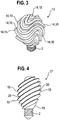
- FIG. 4 shows a further LED lamp 17 with a lamp body 18, which identifies annular structures.
- the annular elevations 19 or depressions 20 are with respect to the longitudinal axis the LED lamp 17 inclined by about 45 °. This has the advantage that the cooling by the convection in horizontal or vertical arrangement of the LED lamp 17 works equally well.
- FIG. 5 shows a further LED lamp 21 with a lamp body 22, in which for a particularly good cooling, the structuring of the surface results in a lamellar structure.
- the slats 23 are arranged parallel to each other.
- FIG. 6 shows the LED lamp 21 off FIG. 5 in supervision.
- the through holes 24 in the lamp body 22 can be seen.
- FIG. 7 and FIG. 8 show a further LED lamp 25 with a lamp body 26, wherein the structuring of the surface also gives a lamellar structure.
- FIG. 8 schematically shows a cross section through the lamp body approximately in the middle height. In this embodiment, however, the slats 27 are arranged in a star shape. How out FIG. 7 to recognize the outline in side view that of a conventional light bulb.
- the coupling of the LED light in the lamp body can be done in various ways. Show this FIG. 9 to FIG. 11 Examples of LED modules that can be used in the above lamp body.
- the LED modules have a carrier equipped with LEDs on.
- a carrier a conventional printed circuit board, a metal core board, or any other suitable pad can be used.
- a metal core board preferably has a structured copper layer on a dielectric, for example made of polyimide or epoxy resin, and a substrate, for example of aluminum, copper or another metal on. The heat generated on the board is emitted very effectively over the cross-sectional area.
- FIG. 9 an LED module 28 with a flat LED carrier 29 extending away from the threaded socket or lamp socket 2. LEDs 30 are mounted on both sides of the carrier 29.
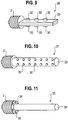
- FIG. 10 shows an LED module 31 with a cylindrical support 32, at the periphery LEDs 30 are mounted regularly.
- FIG. 11 shows an LED module 33 with a flat, round (disk-shaped) support 34, on which LEDs 30 are mounted in a ring, and with a highly thermally conductive, cylindrical core 35.
- the core 35 extends along the longitudinal axis of the LED lamp.
- the core 35 may comprise, for example, carbon, aluminum and / or copper.
- the core 35 is provided with a light-reflecting surface (e.g., film [not numbered]) to improve the luminous efficacy.
- This reflective layer may include barium sulfate, phosphors or other suitable ingredient.
- the core 35 is dimensioned so that it can be inserted into the recess provided in a lamp body.
- LED carriers may have ramifications. This can be advantageous both for the heat distribution and for the distribution of the light emitted by the LEDs within the lamp body.
- FIG. 12 shows a schematic cross section through such an LED lamp 36.
- the carrier is in the form of a frame 37, which has substantially the contours of the LED lamp 36, but strictly complies with the standardized outlines.
- the framework has a vertical section equipped with LEDs 30, from which branchings 38 extend laterally.
- the framework 37 is provided with LEDs 30 and possibly with the necessary driver and control electronics (not shown).
- the framework 37 is embedded in the lamp body 39 of the LED lamp 36.
- the lamp body 39 forms in the region of the ramifications 38 lamellae, which extend in the plane perpendicular to the sheet direction.
- FIG. 13 shows a further embodiment of an LED lamp 40 with a lamp body 41 with a support in the form of a star-shaped framework or with star-shaped outgoing branches 42.
- the lamp body 40 also forms in the region of the branches 42 slats, which are perpendicular to the sheet direction in the plane extend.
- the LED lamps after FIG. 12 and FIG. 13 can be made so that first the carrier is equipped with at least the LEDs, then the carrier is at least partially immersed for a certain time in a bath with the lamp body forming Umhüllmasse and then the Umhüllmasse is cured.
- the lamp base is placed on the loading of the carrier.
- the wrapping compound is made of thermoplastic and / or an epoxy material.
- the cladding diffuses light diffusely by specifically scattering centers are introduced.
- the wrapping compound is also milky white. The curing takes place thermally, chemically and / or with the use of UV light.
- the LED module can be used, for example, precisely fitting in a corresponding recess in the lamp body.
- the LED module may be connected to the lamp body by means of a thread.
- LEDs may be disposed on a flexible support (eg, a so-called flex board).
- the carriers have a good light-reflecting surface.
- the surface of the support may generally include BaS0 4 , phosphors, metallization and much more.
- the LEDs can be arranged flat.
Landscapes
- Engineering & Computer Science (AREA)
- General Engineering & Computer Science (AREA)
- Physics & Mathematics (AREA)
- Microelectronics & Electronic Packaging (AREA)
- Optics & Photonics (AREA)
- Non-Portable Lighting Devices Or Systems Thereof (AREA)
- Arrangement Of Elements, Cooling, Sealing, Or The Like Of Lighting Devices (AREA)
- Led Device Packages (AREA)
- Fastening Of Light Sources Or Lamp Holders (AREA)
Description
- Die Erfindung betrifft eine Leuchtdioden (LED)-Lampe und ein Verfahren zum Herstellen einer LED-Lampe.
- Trotz bekannter Vorteile der LED im Vergleich zu anderen Lichtquellen bezüglich Lebensdauer, Zuverlässigkeit, Robustheit und Effizienz können LED-basierte Lichtquellen die traditionellen Lichtquellen bisher noch nicht in allen Anwendungsbereichen ersetzen. Nicht zuletzt liegt dies am thermischen Verhalten der Leuchtdioden: beim Überschreiten der maximal zulässigen Temperatur, der sogenannten Junction-Temperatur, die typischerweise im Bereich von 120 - 160 °C liegt, werden die LEDs zerstört. Auch die Lebensdauer der LEDs hängt stark von der Betriebstemperatur ab. Deswegen benötigt man zusätzliche Maßnahmen, um das thermische Verhalten der LED-Systeme in den Griff zu bekommen. Außerdem können LEDs in der Regel nicht ohne weiteres am Netz betrieben werden, sondern benötigen spezielle Treiber bzw. Stromregler, da LEDs an sich stromgesteuerte Element sind. Ferner weichen bekannte LED-Strahler stark von der der Form einer konventionellen Glühbirne ab, was für eine Kundenakzeptanz nachteilig ist. Bekannt ist beispielsweise eine LED-Lampe mit E27-Sockel zum Betrieb bei 230 V, bei der die LEDs zur ausreichenden Kühlung freiliegend ohne Abdeckung auf einem flachen Träger montiert sind.
- Aufgrund dieser Probleme gibt es noch keinen vollwertigen Ersatz zu Glühbirnen durch LED-Retrofits.
- Eine Weißlicht-Kolbenanordnung weist einen zylindrischen Körper mit einem ringförmigen Vorsprung, der sich von einer Bodenfläche des zylindrischen Körpers erstreckt, einen Kolben, der auf der Oberseite des zylindrischen Körpers angebracht ist, und mehrere Leuchtdioden, die innerhalb des Kolbens angeordnet sind, um elektrisch mit dem ringförmigen Vorsprung und einer in dem Kolben aufgenommenen Leiterplatte verbunden zu sein, auf. Der Kolben weist mehrere erste Nuten, die in einer Außenfläche des Kolbens definiert sind, und mehrere zweite Nuten, die in einer Innenfläche des Kolbens definiert sind, auf, Licht von den Leuchtdioden zu reflektieren und zu brechen. Die ersten Nuten kreuzen die zweiten Nuten in einem Winkel, der die Reflexion und Brechung des Lichts zu verstärken.
-
DE 10 2007 017 900 A1 offenbart ein Leuchtmittel mit einem Kolben. Der Kolben hat eine Kolbenachse und eine Kolbenwand aus lichtdurchlässigem Material, die wenigstens teilweise einen Innenraum des Kolbens begrenzt. Ein erstes Kontaktelement und ein zweites Kontaktelement sind mit Spannung beaufschlagbar und im Innenraum des Kolbens angeordnet. Wenigstens ein Halbleiter-Leuchtchip, welcher bei Spannungsbeaufschlagung Licht emittiert, ist mit dem ersten und dem zweiten Kontaktelement verbunden. Die Kolbenwand ist außen wärmeleitend mit einer Konvektions-Kühlstruktur verbunden. Der Innenraum des Kolbens kann mit einer wärmeleitenden Flüssigkeit in Form von Silikonöl gefüllt sein. Durch das Silikonöl wird von dem Halbleiter-Leuchtchip erzeugte Wärme zur Umfangswand des Kolbens und darüber zu einer außen wärmeleitend mit der Kolbenwand verbundenen Konvektions-Kühlstruktur abgeführt. - Es ist daher die Aufgabe der Erfindung, einem Ersatz konventionellen Lampen, und speziell konventioneller Glühbirnen, durch Lampen auf LED-Basis näherzukommen.
- Die Aufgabe wird durch LED-Lampen nach den unabhängigen Ansprüchen gelöst. Vorteilhafte Ausgestaltungen sind insbesondere den Unteransprüchen einzeln oder in Kombination entnehmbar.
- Die LED-Lampe weist mindestens einen mit mindestens einer LED bestückten Träger auf, sowie einen Lampensockel bzw. eine Fassung zum Stromanschluss, und weiter mindestens eine dem Lampensockel und der mindestens einen LED zwischengeschaltete Schaltungskomponente zum Betreiben der mindestens einen LED. Ferner weist die LED-Lampe einen Lampenkörper zur Aufnahme zumindest des Teils des Trägers, der die LED trägt, auf, wobei der Lampenkörper zur Kühlung der LED-Lampe durch Wärmekonvektion eine Oberflächenstrukturierung aufweist. Die Oberflächenstrukurierung weist eine Vielzahl von Erhebungen bzw. Vertiefungen auf. Die Erhebungen sind jeweils in Form von Inseln ausgebildet. Der Lampenkörper weist ferner eine Ausnehmung zur Aufnahme zumindest des Teils des Trägers auf, der die mindestens eine LED trägt.
- Durch die Oberflächenstrukturierung wird die Oberfläche der LED-Lampe bzw. Lampenkörpers vergrößert (je nach Form und Art der Strukturierung um bis zu mehr als das 100-fache im Vergleich zu einer Standardglühbirne vergleichbarer Leuchtstärke), so dass eine Kühlung durch Verstärkung des Wärmetransports zwischen der Lampenoberfläche und der Umgebung durch freie Konvektion begünstigt wird. Die LED-Lampe kann in einem weiten Leistungsbereich ohne Verwendung externer passiver Kühlkörper oder aktiver Kühlmittel betrieben werden, was den Einsatz solcher Lampen mit ausreichender Beleuchtung mit bereits vorhandenen Sockeln (z. B. Edison-Sockeln nach DIN 40400 wie E26/E27, E14 oder Bajonett-Sockeln wie B22d, und so weiter) erst möglich macht. Die Oberflächenvergrößerung durch die Oberflächenstrukturierung kann beispielsweise durch sog. 3D-Scanning mit nachfolgender Digitalisierung der Oberfläche des Objekts bestimmt werden.
- Die Art und Zahl der LEDs ist nicht beschränkt. So können ein oder mehrere einfarbige (einschließlich weißer) LEDs verwendet werden, oder verschiedenfarbige LEDs, z. B. mindestens zwei LEDs unterschiedlicher Farben, vorzugsweise der RGB-Grundfarben, z. B. nach den Mustern RGB, RGGB, RRGB und so weiter. Auch können in Reihe geschaltete LEDs oder LED-Cluster verwendet werden, sog. LED-Ketten, oder parallel geschaltete LEDs.
- Als Träger können eine gewöhnliche Platine, eine Metallkernplatine zur verbesserten Wärmeabfuhr oder andere geeignete Unterlagen verwendet werden. Die Metallkernplatine weist vorzugsweise eine strukturierten Kupferschicht auf einem Dielektrikum, z.B. aus Polyimid oder Epoxydharz, und ein Substrat, z.B. aus Aluminium-, Kupfer- oder einem anderen Metall, auf. Dabei wird die auf der Platine erzeugte Wärme über die Querschnittsfläche besonders effektiv abgegeben. Der Träger ist vorzugsweise daraufhin optimiert, dass die beim Betrieb generierte Wärme gut im Inneren des Lampenkörpers verteilt wird.
- Die Schaltungskomponente zum Betreiben der LED(s) umfasst vorzugsweise eine Treiberschaltung zur Schaltung antiparallel geschalteter LEDs, aufweisend einen einfachen Gleichrichter mit einer LED bzw. einer LED-Kette in einem jeweiligen Ast des Gleichrichters, und ferner einen Strombegrenzer (z. B. einen Widerstand und / oder einen Stromregler), sowie ein Schaltnetzteil, vorzugsweise in Form eines Flyback-Converters.
- Bevorzugt wird eine LED-Lampe, bei welcher sich der Umriss des Lampenkörpers in einen Umriss einer herkömmlichen Glühbirne einpasst. Trotz der Oberflächenstrukturierung behält die LED-Lampe somit im Wesentlichen die vertrauten Konturen und Abmessungen bzw. Form der konventionellen Glühbirne (z. B. Edison-Bulb) bei, was für die Kundenakzeptanz eine wichtige Rolle spielen kann. Jedoch kann es bevorzugt sein, wenn der Lampenkörper sich auch in andere geometrische Formen außer der Edison-Bulb im Rahmen anderer genormter Umrisse bzw. Konturen (sog. Outlines) einpasst, z. B. vom Typ A19.
- Vorzugsweise weisen Inseln jeweils eine in Aufsicht runde oder viereckige Grundform auf, wobei die viereckige Grundform zur vereinfachten Reinigung insbesondere mit abgerundeten Ecken ausgebildet ist.
- Die Aufgabe wird auch gelöst durch LED-Lampe, aufweisend mindestens einen mit mindestens einer LED bestückten Träger, einen Lampensockel, mindestens eine dem Lampensockel und der mindestens einen LED zwischengeschaltete Schaltungskomponente zum Betreiben der mindestens einen LED, einen Lampenkörper aus lichtdurchlässigem Material, wobei der Lampenkörper zur Kühlung durch Wärmekonvektion eine Oberflächenstrukturierung aufweist und wobei die Oberflächenstrukurierung eine Vielzahl von Erhebungen aufweist, wobei der Lampenkörper eine Ausnehmung zur Aufnahme zumindest des Teils des Trägers, der die mindestens eine LED trägt, aufweist, die Erhebungen jeweils eine längliche Grundform aufweisen und die Erhebungen entlang gekrümmter Trajektorien laufen und insbesondere S-förmige Abschnitte beinhalten.
- In noch einer Lösung der Aufgabe können die Erhebungen jeweils eine ringförmige Grundform aufweisen. Dabei kann es bevorzugt sein, wenn die Erhebungen jeweils bezüglich einer Symmetrieachse, insbesondere Längsachse, z. B. optischen Achse, der LED-Lampe geneigt sind, insbesondere in einem Bereich von bis zu 45°, speziell um 45°.
- Es kann auch bevorzugt sein, wenn die Erhebungen in Form von Lamellen vorliegen.
- Dann kann es bevorzugt sein, wenn die Lamellen im Wesentlichen parallel zueinander ausgerichtet sind. Alternativ kann es bevorzugt sein, wenn die Lamellen im Wesentlichen sternförmig ausgerichtet sind.
- In noch einer weiteren Lösung der Aufgabe ist der Träger flächig ausgebildet, und eine Vielzahl von LEDs sind auf ihm verteilt montiert. Der LED-Träger ist ferner als Gerüst mit mehreren Verästelungen ausgebildet. Der Träger weist zudem eine ebene, runde Grundform auf, von der sich ein gut wärmeleitender Kern entlang der Längsachse der LED-Lampe weg erstreckt. Der Kern weist eine lichtreflektierende Oberfläche, insbesondere mit Bariumsulfat, auf. Darüber hinaus weist die reflektierende Oberfläche einen Leuchtstoff auf. Die LED-Lampe weist ferner einen Wärmeaustauscher zum Wärmeaustausch zwischen dem Träger und dem Lampenkörper auf.
- Es kann bevorzugt sein, wenn die Verästelungen zueinander parallel angeordnet sind.
- Es kann alternativ bevorzugt sein, wenn die Verästelungen in Aufsicht sternförmig zueinander angeordnet sind.
- Vorzugsweise weist der Kern Kohlenstoff, Aluminium und / oder Kupfer auf.
- Der Wärmeaustauscher weist zur guten Wärmeleitung bevorzugt Metall, eine Metallverbindung, Graphit und / oder Nanoröhrchen auf.
- Der Wärmeaustauscher kann zumindest bis zur Oberfläche des Lampenkörpers reichen, kann also auch aus dem Lampenkörper zumindest teilweise herausragen. Dabei sollten vorzugsweise genormte maximal zulässige Lampen-Outlines eingehalten werden (z. B. A19).
- Es kann eine LED-Lampe bevorzugt sein, bei welcher die LEDs auf einer ebenen Oberfläche des LED-Trägers montiert sind, wobei der LED-Träger sich von dem Lampensockel weg erstreckt.
- Es kann alternativ eine LED-Lampe bevorzugt sein, bei welcher der Träger eine zylindrische Grundform aufweist
- Der Lampenkörper weist als Material vorzugsweise Thermoplast, Polycarbonat, Teflon und / oder Epoxy-Harz auf, ist aber nicht darauf beschränkt.
- Der Lampenkörper ist vorzugsweise als im sichtbaren Spektrum diffus streuendes optisches Medium ausgebildet. Dazu weist der Lampenkörper bevorzugt Streuzentren (z. B. Kügelchen und / oder Bläschen) auf. Die Streuzentren können sowohl im Lampenkörper als auch an dessen Oberfläche vorgesehen sein.
- Der Lampenkörper weist vorzugsweise einen Leuchtstoff auf. Der Leuchtstoff weist vorzugsweise durchsichtige organische Leuchtstoffe und / oder Selten-Erd-Komplexe mit organischem Phosphor, und so weiter, auf.
- Es ist ferner vorteilhaft, dass die LED-Lampe ein fluidisches Kühlmedium zwischen dem Lampenkörper und dem Träger aufweist, insbesondere ein gut wärmeleitendes Kühlmedium.
- Das Fluid kann in unmittelbaren Kontakt mit der mindestens einen LED (gehäust oder ungehäust) stehen.
- Als Kühlmedium wird vorzugsweise Wasser, Ethanol, oder eine Ethanol-Wasser-Mischung verwendet, ist aber nicht darauf beschränkt. Alkohol ist ungiftig, niedrigviskos, transparent, hat eine verhältnismäßig hohe Wärmekapazität und einen niedrigen Gefrierpunkt. Glykol-, Ethylenglykol- und / oder Glyzerin-Zusätze können ebenfalls vorteilhaft verwendet werden.
- Vorzugsweise ist das Kühlmedium diffus lichtstreuend und / oder milchig weiß und / oder teilweise transparent.
- Das Kühlmedium enthält einen Leuchtstoffzusatz, insbesondere eine Phosphor-Verbindung, und so weiter.
- In einer anderen Lösung ist das Kühlmedium niedrigviskos, um den Wärmeaustausch zwischen dem Lampenkörper und dem LED-Modul durch Konvektion zu begünstigen. Es weist vorzugsweise eine hohe Wärmekapazität und / oder eine hohe Umwandlungswärme bei einem Übergang von einer Phase in eine andere Phase auf.
- Das LED-Modul bzw. LED-Träger kann in noch einer Lösung derart ausgebildet sein, dass je nach Orientierung der LED-Lampe die Wärme-Quelle(n) eine für die Konvektion des Fluids günstige Position einnehmen. Dies ist dadurch gewährleistet, dass der LED-Träger ausreichende Flexibilität besitzt, somit er bei einer Änderung der Orientierung der LED-Lampe der Schwerkraft nachgibt und auf diese Weise die ggf. räumlich verteilte Wärmequelle(n), typischerweise die LEDs und ggf. Schaltungskomponenten, nach unten versetzt.
- Es kann auch bevorzugt sein, wenn die LED-Lampe zusätzlich oder alternativ als Oberflächenstrukturierung mindestens einen Luftdurchlass zwischen der Ausnehmung zur Aufnahme des LED-Moduls und der Außenseite des Lampenkörpers ermöglicht; der Lampenkörper also luftdurchlässig ist.
- Vorzugsweise sind in der Ausnehmung Kühlrippen angeordnet, die thermisch zumindest an die LEDs gut angekoppelt sind, vorzugsweise auch an Elektronikkomponenten. Die Ankopplung geschieht vorzugsweise unter Verwendung gut wärmeleitender Materialien und / oder durch Wärmerohre ("Heat Pipes"), es sind aber auch andere Ankopplungsarten möglich. Die Kühlrippen sind bevorzugt so angeordnet, dass sie oder jeweils einige von ihnen in jeder Brennlage der Lampe ausreichend wirksam sind.
- Vorzugsweise weist die Oberflächenstrukturierung zumindest eine Öffnung durch den Lampenkörper auf.
- Es ist außerdem noch eine Lösung, dass die LED-Lampe ein Drahtnetz aufweist, dessen Zwischenräume zumindest teilweise offen sind.
- Bevorzugt kann die mindestens eine Schaltungskomponente so eingerichtet ist, dass die LED-Lampe mittels Phasenanschnitt- und / oder Phasenabschnitt-Dimmern dimmbar ist.
- Vorzugsweise kann die LED-Lampe über eine Steuerung verfügen, die Dimming und/oder eine Steuerung der Farbtemperatur ermöglicht. Beispielsweise kann dies durch spezielle Knöpfe bzw. Schalter an oder in der LED-Lampe geschehen, die z. B. durch Wippen des Lampenkörpers in Bezug auf den Sockel aktiviert werden können.
- Alternativ oder zusätzlich kann die LED-Lampe über Schall, Ultraschall, Funkwellen und / oder Infrarotstrahlung ferngesteuert werden.
- Vorzugsweise ist die mindestens eine Schaltungskomponente so eingerichtet, dass über sie eine Farbtemperatur steuerbar ist.
- Bevorzugt wird ferner zur einfachen Herstellung und zum einfachen Zusammenbau eine LED-Lampe, bei welcher der Träger und der Lampensockel ein LED-Modul bilden.
- Bevorzugt wird für eine kompakte Bauweise ferner eine LED-Lampe, bei welcher der Träger sowohl mit mindestens einer LED als auch mit mindestens einer Schaltungskomponente bestückt ist. Alternativ können die Schaltungskomponenten z. B. auch auf einem separaten Trägen montiert sein.
- Bevorzugt wird insbesondere eine LED-Lampe bei welcher durch die Oberflächenstrukturierung die Oberfläche des Lampenkörpers um bis zu mehr als das 100-fache im Vergleich zu einem nicht oberflächenstrukturierten Lampenkörper entsprechenden Umrisses vergrößert wird, insbesondere bis zu 20-fach, speziell zwei- bis zehnfach.
- Die LED-Lampen wie hierin beschrieben lassen sich mittels eines Verfahrens, das die folgenden Schritte aufweist, herstellen: Bestücken eines Trägers mit mindestens einer LED; Eintauchen des Trägers mindestens teilweise in ein Bad mit einer Umhüllmasse und Aushärtenlassen der Umhüllmasse.
- Diesem geht vorzugsweise ein Bereitstellen eines Trägers / Trägersystems / Gerüsts aus (Teil-)Trägern, z. B. in Form einer üblichen Leiterplatte, z. B. mit Metall, z. B. als Metallkernplatine, aber auch aus Kunststoff oder Keramik, voran.
- Bevorzugt weist das Verfahren nach dem Schritt des Bestückens des Trägers einen Schritt eines Formens des Trägers auf.
- Bevorzugt weist das Verfahren nach dem Schritt des Bestückens des Trägers einen Schritt eines Aufsetzens eines Sockels auf den Träger auf.
- Vorzugsweise wird der Träger mit LEDs unterschiedlicher Farben bestückt.
- Vorzugsweise wird der Träger mit mindestens einer Schaltungskomponente (Treiber- und / oder Steuerkomponente) zum Betreiben der mindestens einen LED bestückt.
- Bevorzugt weist die Umhüllmasse ein Thermoplast und / oder ein Epoxymaterial auf.
- Die Umhüllmasse kann vorzugsweise diffus lichtstreuend, milchig weiß und / oder mit Streuzentren (z. B. Kügelchen / Bläschen) versehen sein und / oder Leuchtstoffe (z. B. grünen Phosphor und oder gelben Phosphor) aufweisen.
- Bevorzugt wird ein thermisches, chemisches oder durch UV-Licht hervorgerufenes Aushärten der Umhüllmasse. Der Sockel kann sowohl vor als auch nach dem Aushärten aufgesetzt werden.
- Das Verfahren ergibt unter anderem die folgenden Vorteile:
- Die optischen Eigenschaften des Lampenkörpers können leicht modifiziert werden, indem man der sich im flüssigen Zustand befindlichen Umhüllmasse entsprechende Zusätze beimischt. Die gewünschte Form der LED-Lampe mit vergrößerter Oberfläche kann ferner durch die Anpassung der Viskosität der Benetzbarkeit der Umhüllmasse bezüglich des mit den LED bestückten Gerüsts erreicht werden. Wärmequellen können nah an der Oberfläche des Lampenkörpers platziert werden, wodurch der Wärmeaustausch mit der Umgebung begünstigt wird.
- In den folgenden Ausführungsbeispielen wird die Erfindung schematisch genauer dargelegt. Gleiche oder gleichwirkende Bauelemente können über mehrere Figuren hinweg mit gleichen Bezugszeichen versehen sein.
- FIG 1-2
- zeigen in Seitenansicht jeweils eine andere Ausführungsform einer erfindungsgemäßen LED-Lampe;
- FIG 3
- zeigt in Schrägansicht noch eine andere Ausführungsform einer erfindungsgemäßen LED-Lampe;
- FIG 4
- zeigt in Seitenansicht noch eine andere Ausführungsform einer erfindungsgemäßen LED-Lampe;
- FIG 5
- zeigen in Schrägansicht noch eine andere Ausführungsform einer erfindungsgemäßen LED-Lampe;
- FIG 6
- zeigt in Aufsicht die LED-Lampe aus
FIG 5 ; - FIG 7
- zeigt in perspektivischer Ansicht noch eine weitere Ausführungsform einer erfindungsgemäßen LED-Lampe;
- FIG 8
- zeigt in Vorderansicht einen Querschnitt durch die LED-Lampe aus
FIG 7 ; - FIG 9-11
- zeigen jeweils unterschiedliche Ausführungsformen eines LED-Moduls;
- FIG 12-13
- zeigen als Schnittdarstellung in Vorderansicht jeweils noch eine weitere Ausführungsform einer erfindungsgemäßen LED-Lampe.
-
FIG 1 zeigt eine LED-Lampe 1 mit einem LED-Modul mit einem Träger (ohne Abb.) und einer mit dem Träger verbundenen Lampenfassung bzw. Lampensockel 2 in Form eines Edisonsockels, aufweisend einen Außenkontakt 3 und einen Fußkontakt 4.
Der Träger ist mit mindestens einer LED und mindestens einer dem Lampensockel und der mindestens einen LED zwischengeschalteten Schaltungskomponente zum Betreiben der LED bestückt (ohne Abb.). Die LED-Lampe 1 weist ferner einen Lampenkörper 5 mit einer Ausnehmung zur Aufnahme zumindest des Teils des Trägers, der die mindestens eine LED trägt, auf (ohne Abb.). Der Lampenkörper 5 weist zur Kühlung der LED-Lampe 1 durch Wärmekonvektion eine Oberflächenstrukturierung auf. Die Oberflächenstrukturierung umfasst eine Vielzahl von in Aufsicht runden Erhebungen 6 bzw. Vertiefungen 7 auf. Diese sind weitgehend über die Oberfläche gleichverteilt. - Trotz der Strukturierung entspricht die Form des Leucht- bzw. Lampenkörpers 5 bzw. LED-Lampe im Wesentlichen der Form einer konventionellen Glühbirne. Zur Verdeutlichung ist der Umriss 8 eingezeichnet, der im Wesentlichen die Form einer konventionellen Glühbirne wiedergibt.
- Auf diese Weise kann die Oberfläche des Lampenkörpers 5 um ein Mehrfaches vergrößert werden. Außerdem ist der Leuchtkörper 5 leicht zu reinigen. Durch die gezeigte Strukturierung 6 bzw. 7 kann die Oberfläche je nach Anzahl und Höhe der Erhebungen 6 bzw. Vertiefungen 7 zwei- bis zehnmal ohne weiteres vergrößert werden. Bei einer stärkeren Strukturierung kann sogar eine mehr als zwanzigfache Oberflächenvergrößerung erreicht werden.
-
FIG 2 zeigt eine weitere LED-Lampe 9 mit dem Lampenkörper 10, der Erhebungen 11 in Form von in viereckigen abgeflachten Inseln und Vertiefungen 12 in Form von die Inseln voneinander trennenden Kanälen aufweist. Auch eine solche Oberflächenstrukturierung kann eine mehrfache Vergrößerung der Oberfläche im Vergleich mit einer glatten Oberfläche bewirken. Um die Handhabung und Reinigung solcher Lampenkörper 10 zu erleichtern, können die viereckigen Strukturen 11 an den Ecken abgerundet sein -
FIG 3 zeigt eine weitere LED-Lampe 13 mit einem Lampenkörper 14, der längliche Erhebungen 15 und längliche Vertiefungen 16 an seiner Oberfläche aufweist. Die länglichen Erhebungen 15 und Vertiefung 16 verlaufen entlang gekrümmter Trajektorien, sodass sie S-förmige Abschnitte aufweisen. Diese Anordnung ist besonders gut geeignet, um einen ausreichenden Wärmeaustausch mit der Umgebung unabhängig von der Orientierung der LED-Lampe 13 zu ermöglichen. -
FIG 4 zeigt eine weitere LED-Lampe 17 mit einem Lampenkörper 18, der ringförmige Strukturen ausweist. Die ringförmigen Erhebungen 19 bzw. Vertiefungen 20 sind bezüglich der Längsachse der LED-Lampe 17 um ca. 45° geneigt. Dies hat den Vorteil, dass die Kühlung durch die Konvektion bei waagerechter oder senkrechter Anordnung der LED-Lampe 17 gleichermaßen gut funktioniert. -
FIG 5 zeigt eine weitere LED-Lampe 21 mit einem Lampenkörper 22, bei dem für eine besonders gute Kühlung die Strukturierung der Oberfläche eine lamellenartige Struktur ergibt. In diesem Ausführungsbeispiel sind die Lamellen 23 zueinander parallel angeordnet. -
FIG 6 zeigt die LED-Lampe 21 ausFIG 5 in Aufsicht. Zusätzlich zu den Merkmalen ausFIG 5 sind in dieser Darstellung die Durchgangslöcher 24 im Lampenkörper 22 erkennbar. -
FIG 7 und FIG 8 zeigen eine weitere LED-Lampe 25 mit einem Lampenkörper 26, bei dem die Strukturierung der Oberfläche ebenfalls eine lamellenartige Struktur ergibt.FIG 8 zeigt schematisch einen Querschnitt durch den Lampenkörper ungefähr in der mittleren Höhe. In diesem Ausführungsbeispiel sind die Lamellen 27 allerdings sternförmig angeordnet. Wie ausFIG 7 zu erkennen, entspricht der Umriss in Seitenansicht dem einer herkömmlichen Glühbirne. - Die Einkopplung des LED-Lichts in den Lampenkörper kann auf verschiedene Weise erfolgen. Dazu zeigen
FIG 9 bis FIG 11 Beispiele von LED-Modulen, die in den obigen Lampenkörper eingesetzt werden können. Die LED-Module weisen einen mit Leuchtdioden bestückten Träger auf. Als Träger kann eine übliche Leiterplatte, eine Metallkernplatine, oder jede andere geeignete Unterlage benutzt werden. Eine Metallkernplatine weist bevorzugt eine strukturierte Kupferschicht auf einem Dielektrikum, z.B. aus Polyimid oder Epoxydharz, auf sowie ein Substrat, z.B. aus Aluminium-, Kupfer- oder einem anderen Metall, auf. Dabei wird die auf der Platine erzeugte Wärme über die Querschnittsfläche besonders effektiv abgegeben. - Im Einzelnen zeigt
FIG 9 ein LED-Modul 28 mit einem flachen LED-Träger 29, der sich weg von der Gewindefassung bzw. Lampensockel 2 erstreckt. LEDs 30 sind beidseitig auf dem Träger 29 angebracht. -
FIG 10 zeigt ein LED-Modul 31 mit einem zylindrischen Träger 32, an dessen Umfang LEDs 30 regelmäßig angebracht sind. -
FIG 11 zeigt ein LED-Modul 33 mit einem flachen, runden (scheibenförmigen) Träger 34, auf dem LEDs 30 ringförmig montiert sind, und mit einem gut wärmeleitenden, zylinderförmigen Kern 35. Der Kern 35 erstreckt sich entlang der Längsachse der LED-Lampe. Der Kern 35 kann beispielsweise Kohlenstoff, Aluminium und / oder Kupfer aufweisen. Der Kern 35 ist mit einer lichtreflektierenden Oberfläche (z. B. Schicht bzw. Folie [ohne Bezugszeichen]) versehen, um die Lichtausbeute zu verbessern. Diese reflektierende Schicht kann Bariumsulfat, Leuchtstoffe oder andere geeignete Inhaltsstoff aufweisen. Der Kern 35 ist so dimensioniert, dass er in die dafür vorgesehene Ausnehmung in einen Lampenkörper eingesetzt werden kann. - In einigen Ausführungsformen können LED-Träger Verästelungen aufweisen. Dies kann vorteilhaft sowohl für die Wärmeverteilung als auch für die Verteilung des von den LEDs emittierten Lichtes innerhalb des Lampenkörpers sein.
-
FIG 12 zeigt einen schematischen Querschnitt durch eine solche LED-Lampe 36. Der Träger liegt in Form eines Gerüsts 37 vor, das im Wesentlichen die Konturen der LED-Lampe 36 aufweist, jedoch streng die genormten Outlines einhält. Das Gerüst weist einen senkrechten, mit LEDs 30 bestückten Abschnitt auf, von dem hier seitlich Verästelungen 38 abgehen. Das Gerüst 37 ist mit LEDs 30 und ggf. mit der nötigen Treiber- und Steuerelektronik (ohne Abb.) versehen. Das Gerüst 37 ist in dem Lampenkörper 39 der LED-Lampe 36 eingebettet. Der Lampenkörper 39 bildet im Bereich der Verästelungen 38 Lamellen, die sich in die Ebene senkrecht zur Blattrichtung erstrecken. -
FIG 13 zeigt ein weiteres Ausführungsbeispiel einer LED-Lampe 40 mit einem Lampenkörper 41 mit einem Träger in Form eines sternförmigen Gerüsts bzw. mit sternförmig abgehenden Verästelungen 42. Der Lampenkörper 40 bildet auch hier im Bereich der Verästelungen 42 Lamellen, die sich in die Ebene senkrecht zur Blattrichtung erstrecken. - Die LED-Lampen nach
FIG 12 und FIG 13 können so hergestellt werden, dass zunächst der Träger mit mindestens den LEDs bestückt wird, danach der Träger mindestens teilweise für eine bestimmte Zeit in ein Bad mit einer den Lampenkörper bildenen Umhüllmasse eingetaucht wird und dann die Umhüllmasse ausgehärtet wird. Der Lampensockel wird dem Bestücken des Trägers aufgesetzt. Die Umhüllmasse ist aus Thermoplast und / oder einem Epoxymaterial. Die Umhüllmasse streut Licht diffus, indem gezielt Streuzentren eingebracht werden. Die Umhüllmasse ist ferner milchig weiß. Das Aushärten geschieht thermisch, chemisch und / oder unter Einsatz von UV-Licht. - Selbstverständlich ist die Erfindung nicht auf die gezeigten Ausführungsformen beschränkt.
- In einigen Ausführungsformen der Erfindung kann das LED-Modul beispielsweise passgenau in eine entsprechende Ausnehmung im Lampenkörper eingesetzt werden.
- Optional oder zusätzlich kann das LED-Modul mittels eines Gewindes mit dem Lampenkörper verbunden sein.
- In einigen Ausführungsformen der Erfindung können LEDs auf einem flexiblen Träger (z. B. einer sogenannten Flex-Platine) angeordnet sein.
- Vorzugsweise weisen die Träger eine gut lichtreflektierende Oberfläche auf. Die Oberfläche des Trägers kann allgemein BaS04, Leuchtstoffe, eine Metallisierung und vieles mehr aufweisen. Die LEDs können flächig angeordnet sein.
-
- 1
- LED-Lampe
- 2
- Lampensockel
- 3
- Außenkontakt
- 4
- Fußkontakt
- 5
- Lampenkörper
- 6
- Erhebung
- 7
- Vertiefung
- 8
- Umriss
- 9
- LED-Lampe
- 10
- Lampenkörper
- 11
- Erhebung
- 12
- Vertiefung
- 13
- LED-Lampe
- 14
- Lampenkörper
- 15
- Erhebung
- 16
- Vertiefung
- 17
- LED-Lampe
- 18
- Lampenkörper
- 19
- Erhebung
- 20
- Vertiefung
- 21
- LED-Lampe
- 22
- Lampenkörper
- 23
- Lamelle
- 24
- Durchgangsloch
- 25
- LED-Lampe
- 26
- Lampenkörper
- 27
- Lamelle
- 28
- LED-Modul
- 29
- Träger
- 30
- LED
- 31
- LED-Modul
- 32
- Träger
- 33
- LED-Modul
- 34
- Träger
- 35
- Kern
- 36
- LED-Lampe
- 37
- Gerüst
- 38
- Verästelung
- 39
- Lampenkörper
- 40
- LED-Lampe
- 41
- Lampenkörper
- 42
- Verästelung
Claims (12)
- LED-Lampe (1; 9; 13; 17; 21; 25; 36; 40), aufweisend- mindestens einen mit mindestens einer LED (30) bestückten Träger (29; 32; 34),- einen Lampensockel (2),- mindestens eine dem Lampensockel (2) und der mindestens einen LED (30) zwischengeschaltete Schaltungskomponente zum Betreiben der mindestens einen LED (30),- einen Lampenkörper (5; 10; 14; 18; 22; 26; 39; 41) aus lichtdurchlässigem Material,- wobei der Lampenkörper (5; 10; 14; 18; 22; 26; 39; 41) zur Kühlung durch Wärmekonvektion eine Oberflächenstrukturierung (6, 7; 11, 12; 15, 16; 19, 20; 23; 24; 27; 38; 42) aufweist und- die Oberflächenstrukurierung eine Vielzahl von Erhebungen (6; 11; 15; 19; 23; 27; 38; 42) aufweist,- der Lampenkörper (5; 10; 14; 18; 22; 26; 39; 41) eine Ausnehmung zur Aufnahme zumindest des Teils des Trägers (29; 32; 34), der die zumindest eine LED (30) trägt, aufweist,- die Erhebungen (6; 11; 15) jeweils in Form von Inseln ausgebildet sind.
- LED-Lampe (1; 9) nach Anspruch 1, bei der die Inseln jeweils eine in Aufsicht runde Grundform (6) oder viereckige Grundform (11) aufweisen, wobei die viereckige Grundform (11) insbesondere mit abgerundeten Ecken ausgebildet ist.
- LED-Lampe (1; 9; 13; 17; 21; 25; 36; 40), aufweisend- mindestens einen mit mindestens einer LED (30) bestückten Träger (29; 32; 34),- einen Lampensockel (2),- mindestens eine dem Lampensockel (2) und der mindestens einen LED (30) zwischengeschaltete Schaltungskomponente zum Betreiben der mindestens einen LED (30),- einen Lampenkörper (5; 10; 14; 18; 22; 26; 39; 41) aus lichtdurchlässigem Material,- wobei der Lampenkörper (5; 10; 14; 18; 22; 26; 39; 41) zur Kühlung durch Wärmekonvektion eine Oberflächenstrukturierung (6, 7; 11, 12; 15, 16; 19, 20; 23; 24; 27; 38; 42) aufweist und- wobei die Oberflächenstrukurierung eine Vielzahl von Erhebungen (6; 11; 15; 19; 23; 27; 38; 42) aufweist,- der Lampenkörper (5; 10; 14; 18; 22; 26; 39; 41) eine Ausnehmung zur Aufnahme zumindest des Teils des Trägers (29; 32; 34), der die zumindest eine LED (30) trägt, aufweist,dadurch gekennzeichnet, dass- die Erhebungen (15; 19; 23; 27) jeweils eine längliche Grundform aufweisen und- die Erhebungen (15) entlang gekrümmter Trajektorien laufen und insbesondere S-förmige Abschnitte beinhalten.
- LED-Lampe (1; 9; 13; 17; 21; 25; 36; 40), aufweisend- mindestens einen mit mindestens einer LED (30) bestückten Träger (29; 32; 34),- einen Lampensockel (2),- mindestens eine dem Lampensockel (2) und der mindestens einen LED (30) zwischengeschaltete Schaltungskomponente zum Betreiben der mindestens einen LED (30),- einen Lampenkörper (5; 10; 14; 18; 22; 26; 39; 41) aus lichtdurchlässigem Material,- wobei der Lampenkörper (5; 10; 14; 18; 22; 26; 39; 41) zur Kühlung durch Wärmekonvektion eine Oberflächenstrukturierung (6,7; 11,12; 15,16; 19,20; 23; 24; 27; 38; 42) aufweist,- der Lampenkörper (5; 10; 14; 18; 22; 26; 39; 41) eine Ausnehmung zur Aufnahme zumindest des Teils des Trägers (29; 32; 34), der die zumindest eine LED (30) trägt, aufweist,dadurch gekennzeichnet, dass- der Träger (29; 32; 34) flächig ausgebildet ist und eine Vielzahl von LEDs (30) auf ihm verteilt montiert sind,- der Träger als Gerüst mit mehreren Verästelungen (38; 42) ausgebildet ist,- der Träger (34) eine ebene, runde Grundform aufweist, von der sich ein gut wärmeleitender Kern (35) entlang der Längsachse der LED-Lampe weg erstreckt und bei welcher der Kern (35) eine lichtreflektierende Oberfläche aufweist,- die reflektierende Oberfläche einen Leuchtstoff aufweist und- die LED-Lampe ferner einen Wärmeaustauscher zum Wärmeaustausch zwischen dem Träger und dem Lampenkörper aufweist.
- LED-Lampe (36) nach Anspruch 4, bei der die Verästelungen (38) zueinander parallel angeordnet sind oder die Verästelungen (42) in Aufsicht sternförmig zueinander angeordnet sind.
- LED-Lampe (1; 9; 13; 17; 21; 25; 36; 40), aufweisend- mindestens einen mit mindestens einer LED (30) bestückten Träger (29; 32; 34),- einen Lampensockel (2),- mindestens eine dem Lampensockel (2) und der mindestens einen LED (30) zwischengeschaltete Schaltungskomponente zum Betreiben der mindestens einen LED (30),- einen Lampenkörper (5; 10; 14; 18; 22; 26; 39; 41) aus lichtdurchlässigem Material,- wobei der Lampenkörper (5; 10; 14; 18; 22; 26; 39; 41) zur Kühlung durch Wärmekonvektion eine Oberflächenstrukturierung (6, 7; 11, 12; 15, 16; 19, 20; 23; 24; 27; 38; 42) aufweist, - der Lampenkörper (5; 10; 14; 18; 22; 26; 39; 41) eine Ausnehmung zur Aufnahme zumindest des Teils des Trägers (29; 32; 34), der die zumindest eine LED (30) trägt, aufweist, dadurch gekennzeichnet, dass- sich ein fluidisches Kühlmedium zwischen dem Lampenkörper und dem Träger befindet,- wobei der Träger dergestalt flexibel ausgestaltet ist, dass er bei einer Änderung der Orientierung der LED-Lampe der Schwerkraft nachgibt und dadurch die LEDs nach unten versetzt.
- LED-Lampe (1; 9; 13; 17; 21; 25; 36; 40), aufweisend- mindestens einen mit mindestens einer LED (30) bestückten Träger (29; 32; 34),- einen Lampensockel (2),- mindestens eine dem Lampensockel (2) und der mindestens einen LED (30) zwischengeschaltete Schaltungskomponente zum Betreiben der mindestens einen LED (30),- einen Lampenkörper (5; 10; 14; 18; 22; 26; 39; 41) aus lichtdurchlässigem Material,- wobei der Lampenkörper (5; 10; 14; 18; 22; 26; 39; 41) zur Kühlung durch Wärmekonvektion eine Oberflächenstrukturierung (6, 7; 11, 12; 15, 16; 19, 20; 23; 24; 27; 38; 42) aufweist, - der Lampenkörper (5; 10; 14; 18; 22; 26; 39; 41) eine Ausnehmung zur Aufnahme zumindest des Teils des Trägers (29; 32; 34), der die zumindest eine LED (30) trägt, aufweist, dadurch gekennzeichnet, dass- der Lampenkörper (5; 10; 14; 18; 22; 26; 39; 41) durch ein Drahtnetz gebildet ist.
- LED-Lampe (1; 9; 13; 17; 21; 25; 36; 40) nach einem der vorhergehenden Ansprüche, dadurch gekennzeichnet, dass- der Lampenkörper (5; 10; 14; 18; 22; 26; 39; 41) eine Ausnehmung zur Aufnahme zumindest des Teils des Trägers (29; 32; 34), der die mindestens eine LED (30) trägt, aufweist,- die Erhebungen (15; 19; 23; 27) jeweils eine längliche Grundform aufweisen und- die Erhebungen (19) jeweils eine ringförmige Grundform aufweisen.
- LED-Lampe (17) nach Anspruch 8, bei der die Erhebungen (19) jeweils bezüglich einer Symmetrieachse, insbesondere Längsachse, der LED-Lampe geneigt sind, insbesondere in einem Bereich von bis zu 45°, speziell um 45°.
- LED-Lampe (1; 9; 13; 17; 21; 25; 36; 40) nach einem der vorhergehenden Ansprüche, dadurch gekennzeichnet, dass- der Lampenkörper (5; 10; 14; 18; 22; 26; 39; 41) eine Ausnehmung zur Aufnahme zumindest des Teils des Trägers (29; 32; 34), der die mindestens eine LED (30) trägt, aufweist und- ein fluidisches Kühlmedium zwischen dem Lampenkörper und dem Träger vorhanden ist, das einen Leuchtstoffzusatz enthält.
- LED-Lampe (1; 9; 13; 17; 21; 25; 36; 40) nach einem der vorhergehenden Ansprüche, dadurch gekennzeichnet, dass- der Lampenkörper (5; 10; 14; 18; 22; 26; 39; 41) eine Ausnehmung zur Aufnahme zumindest des Teils des Trägers (29; 32; 34), der die mindestens eine LED (30) trägt, aufweist und- sich ein fluidisches Kühlmedium zwischen dem Lampenkörper und dem Träger befindet,- wobei das Kühlmedium niedrigviskos und / oder eine hohe Wärmekapazität und / oder eine hohe Umwandlungswärme bei einem Übergang von einer Phase in eine andere Phase aufweist.
- LED-Lampe nach einem der Ansprüche 10 bis 11, bei welcher das Kühlmedium diffus lichtstreuend ist.
Applications Claiming Priority (2)
| Application Number | Priority Date | Filing Date | Title |
|---|---|---|---|
| DE102007037820A DE102007037820A1 (de) | 2007-08-10 | 2007-08-10 | LED-Lampe |
| PCT/EP2008/006571 WO2009021695A1 (de) | 2007-08-10 | 2008-08-08 | Led-lampe |
Publications (2)
| Publication Number | Publication Date |
|---|---|
| EP2188566A1 EP2188566A1 (de) | 2010-05-26 |
| EP2188566B1 true EP2188566B1 (de) | 2017-07-12 |
Family
ID=39765022
Family Applications (1)
| Application Number | Title | Priority Date | Filing Date |
|---|---|---|---|
| EP08785464.2A Not-in-force EP2188566B1 (de) | 2007-08-10 | 2008-08-08 | Led-lampe |
Country Status (5)
| Country | Link |
|---|---|
| US (1) | US8662712B2 (de) |
| EP (1) | EP2188566B1 (de) |
| CN (2) | CN101815894B (de) |
| DE (1) | DE102007037820A1 (de) |
| WO (1) | WO2009021695A1 (de) |
Families Citing this family (51)
| Publication number | Priority date | Publication date | Assignee | Title |
|---|---|---|---|---|
| US10340424B2 (en) | 2002-08-30 | 2019-07-02 | GE Lighting Solutions, LLC | Light emitting diode component |
| US8143631B2 (en) | 2008-03-06 | 2012-03-27 | Metrospec Technology Llc | Layered structure for use with high power light emitting diode systems |
| US11266014B2 (en) | 2008-02-14 | 2022-03-01 | Metrospec Technology, L.L.C. | LED lighting systems and method |
| US8007286B1 (en) | 2008-03-18 | 2011-08-30 | Metrospec Technology, Llc | Circuit boards interconnected by overlapping plated through holes portions |
| US8851356B1 (en) | 2008-02-14 | 2014-10-07 | Metrospec Technology, L.L.C. | Flexible circuit board interconnection and methods |
| US10334735B2 (en) | 2008-02-14 | 2019-06-25 | Metrospec Technology, L.L.C. | LED lighting systems and methods |
| US8410720B2 (en) | 2008-04-07 | 2013-04-02 | Metrospec Technology, LLC. | Solid state lighting circuit and controls |
| DE102008047933A1 (de) * | 2008-09-19 | 2010-04-15 | Osram Gesellschaft mit beschränkter Haftung | Beleuchtungsvorrichtung mit einer Leuchtdiode |
| DE102009008096B4 (de) | 2009-02-09 | 2016-10-27 | Osram Gmbh | Kühlkörper für eine Leuchtvorrichtung |
| DE102009009520A1 (de) * | 2009-02-18 | 2010-08-19 | Osram Opto Semiconductors Gmbh | Steckmodul für ein modular aufgebautes Leuchtmittel, Leuchtmodul für das Leuchtmittel sowie modular aufgebautes Leuchtmittel |
| DE102009019227A1 (de) * | 2009-04-28 | 2011-01-13 | Ledon Lighting Jennersdorf Gmbh | LED lamp |
| JP5632909B2 (ja) | 2009-05-28 | 2014-11-26 | コーニンクレッカ フィリップス エヌ ヴェ | 照明装置、及び照明装置の組み立てのための方法 |
| WO2010136920A1 (en) * | 2009-05-28 | 2010-12-02 | Koninklijke Philips Electronics N.V. | Illumination device with an envelope enclosing a light source |
| TW201109579A (en) * | 2009-09-15 | 2011-03-16 | Advanced Connectek Inc | Structure of LED lamp |
| US8414151B2 (en) | 2009-10-02 | 2013-04-09 | GE Lighting Solutions, LLC | Light emitting diode (LED) based lamp |
| US8593040B2 (en) | 2009-10-02 | 2013-11-26 | Ge Lighting Solutions Llc | LED lamp with surface area enhancing fins |
| US9103507B2 (en) | 2009-10-02 | 2015-08-11 | GE Lighting Solutions, LLC | LED lamp with uniform omnidirectional light intensity output |
| DE102009051763A1 (de) * | 2009-11-03 | 2011-05-05 | Osram Gesellschaft mit beschränkter Haftung | Beleuchtungsvorrichtung mit einem Kolben |
| CN102792096A (zh) * | 2010-02-08 | 2012-11-21 | 欧勒·K·尼尔森 | 一种蒸汽冷却的灯 |
| GB2477994A (en) * | 2010-02-23 | 2011-08-24 | Ecolumens Ltd | Liquid cooled semiconductor light |
| DK2542826T3 (en) | 2010-03-03 | 2019-01-14 | Philips Lighting Holding Bv | ELECTRIC LAMP WITH REFLECTOR FOR TRANSFER OF HEAT FROM THE LIGHT SOURCE |
| DE102010013538A1 (de) | 2010-03-31 | 2011-10-06 | Ledo Led Technologie Gmbh | LED-Leuchte als Glühbirnensubstitut |
| WO2011146677A2 (en) * | 2010-05-20 | 2011-11-24 | Light Prescriptions Innovators, Llc | Led light bulb with translucent spherical diffuser and remote phosphor thereupon |
| US10400959B2 (en) * | 2010-11-09 | 2019-09-03 | Lumination Llc | LED lamp |
| RU2447543C1 (ru) * | 2011-01-11 | 2012-04-10 | Юлия Алексеевна Щепочкина | Лампа светодиодная |
| RU2447542C1 (ru) * | 2011-01-11 | 2012-04-10 | Юлия Алексеевна Щепочкина | Лампа светодиодная |
| US9127816B2 (en) | 2011-01-19 | 2015-09-08 | GE Lighting Solutions, LLC | LED light engine/heat sink assembly |
| WO2013067046A2 (en) | 2011-10-31 | 2013-05-10 | Densen Cao | Led light source |
| DE102011085646A1 (de) * | 2011-11-03 | 2013-05-08 | Osram Gmbh | Halbleiterlampe mit Kolben |
| US8668366B2 (en) | 2011-12-07 | 2014-03-11 | Tsmc Solid State Lighting Ltd. | Energy star compliant LED lamp |
| RU2504714C2 (ru) * | 2012-02-15 | 2014-01-20 | Общество с ограниченной ответственностью "Тегас Электрик" | Способ сборки светодиодной лампы и лампа светодиодная |
| US9500355B2 (en) | 2012-05-04 | 2016-11-22 | GE Lighting Solutions, LLC | Lamp with light emitting elements surrounding active cooling device |
| CN102777791B (zh) * | 2012-07-12 | 2015-09-09 | 深圳和而泰照明科技有限公司 | 灯具及其全光角led灯泡 |
| DE202012009071U1 (de) | 2012-09-21 | 2012-11-08 | Carsten Schmidt | LED-Leuchte mit verbessertem Rückstrahlverhalten |
| DE102012217292A1 (de) * | 2012-09-25 | 2014-03-27 | Zumtobel Lighting Gmbh | LED-Leuchte |
| US20150354804A1 (en) * | 2013-01-10 | 2015-12-10 | Franco MIRABELLI | Outdoor public lighting lamp having light-emitting diodes and street lamp or lamp-post provided with such a lamp |
| US10565835B2 (en) | 2013-01-21 | 2020-02-18 | Rtc Inc. | Control and monitoring of light-emitting-diode (LED) bulbs |
| US20140203939A1 (en) * | 2013-01-21 | 2014-07-24 | Rtc Inc. | Control and monitoring of light-emitting-diode (led) bulbs |
| WO2015075042A1 (en) | 2013-11-25 | 2015-05-28 | Koninklijke Philips N.V. | Method for manufacturing a lighting device |
| US10260684B2 (en) | 2013-12-17 | 2019-04-16 | Lumileds Llc | Low and high beam LED lamp |
| USD748840S1 (en) * | 2014-05-27 | 2016-02-02 | Lumens Co., Ltd | Ceiling light fixture |
| TW201600790A (zh) * | 2014-06-27 | 2016-01-01 | 耘成光電有限公司 | 全周光球泡型燈具 |
| US9686887B2 (en) * | 2014-09-15 | 2017-06-20 | Nicholas Michael D'Onofrio | Liquid cooled metal core printed circuit board |
| US9401468B2 (en) * | 2014-12-24 | 2016-07-26 | GE Lighting Solutions, LLC | Lamp with LED chips cooled by a phase transformation loop |
| USD774474S1 (en) * | 2015-02-04 | 2016-12-20 | Xiaofeng Li | Light emitting diodes on a printed circuit board |
| CN205079067U (zh) * | 2015-07-21 | 2016-03-09 | 上海本星电子科技有限公司 | 遥控灯泡及其光束遥控器 |
| CN106468408A (zh) * | 2015-08-17 | 2017-03-01 | 上海本星电子科技有限公司 | 设有遮光部件的遥控灯及其锥形光束遥控器 |
| EP3179153A1 (de) * | 2015-12-11 | 2017-06-14 | Epistar Corporation | Beleuchtungsvorrichtung |
| US10578510B2 (en) * | 2016-11-28 | 2020-03-03 | Applied Materials, Inc. | Device for desorbing molecules from chamber walls |
| US10849200B2 (en) | 2018-09-28 | 2020-11-24 | Metrospec Technology, L.L.C. | Solid state lighting circuit with current bias and method of controlling thereof |
| CN114630986B (zh) * | 2019-10-31 | 2024-10-22 | 昕诺飞控股有限公司 | Led灯丝装置 |
Citations (1)
| Publication number | Priority date | Publication date | Assignee | Title |
|---|---|---|---|---|
| DE102007017900A1 (de) * | 2007-04-13 | 2008-10-16 | Noctron Holding S.A. | Leuchtmittel |
Family Cites Families (18)
| Publication number | Priority date | Publication date | Assignee | Title |
|---|---|---|---|---|
| US5890794A (en) * | 1996-04-03 | 1999-04-06 | Abtahi; Homayoon | Lighting units |
| EP1047903B1 (de) | 1998-09-17 | 2007-06-27 | Koninklijke Philips Electronics N.V. | Led-leuchte |
| US6793374B2 (en) | 1998-09-17 | 2004-09-21 | Simon H. A. Begemann | LED lamp |
| DE20018435U1 (de) | 2000-10-27 | 2001-02-22 | Shining Blick Enterprises Co., Ltd., Taipeh/T'ai-pei | Glühbirne mit darin enthaltenen biegbaren Lampenbirnchen |
| GB2379790A (en) * | 2001-08-21 | 2003-03-19 | Green Logic Associates Ltd | An illuminated light globe containing two immiscible liquids |
| EP1466505B1 (de) * | 2002-01-10 | 2012-08-01 | Osram Ag | Lampe |
| JP2004296245A (ja) * | 2003-03-26 | 2004-10-21 | Matsushita Electric Works Ltd | Ledランプ |
| US6880956B2 (en) * | 2003-07-31 | 2005-04-19 | A L Lightech, Inc. | Light source with heat transfer arrangement |
| WO2005086245A2 (en) | 2004-03-03 | 2005-09-15 | S.C. Johnson & Son, Inc. | Led light bulb with active ingredient emission |
| DE102005013208A1 (de) * | 2004-03-21 | 2005-10-27 | Späth, Christian, Dipl.-Designer | LED-Leuchtdioden Leuchte |
| US7524091B2 (en) | 2004-08-09 | 2009-04-28 | Valeo Sylvania Llc | Led bulb refractive relector |
| US20060034077A1 (en) * | 2004-08-10 | 2006-02-16 | Tsu-Kang Chang | White light bulb assembly using LED as a light source |
| CA2478001A1 (en) | 2004-08-18 | 2006-02-18 | Remco | Led light bulb |
| DE202005008411U1 (de) * | 2005-05-30 | 2005-07-28 | Huang, Hsien-Jung, Yung-Ho | Kühlkörper für ein LED-Leuchtelement |
| JP4410721B2 (ja) | 2005-05-02 | 2010-02-03 | シチズン電子株式会社 | バルブ型led光源 |
| CN2864338Y (zh) | 2006-01-10 | 2007-01-31 | 孙文明 | Led棒状节能灯泡 |
| US20070195544A1 (en) * | 2006-01-26 | 2007-08-23 | Graves Chester Jr | Remote controlled LED light bulb |
| DE202007003679U1 (de) * | 2007-03-09 | 2007-05-16 | Hong Kuan Technology Co., Ltd., Sinjhuang City | Leuchtdiodenlampe |
-
2007
- 2007-08-10 DE DE102007037820A patent/DE102007037820A1/de not_active Withdrawn
-
2008
- 2008-08-08 WO PCT/EP2008/006571 patent/WO2009021695A1/de not_active Ceased
- 2008-08-08 CN CN2008801028755A patent/CN101815894B/zh not_active Expired - Fee Related
- 2008-08-08 EP EP08785464.2A patent/EP2188566B1/de not_active Not-in-force
- 2008-08-08 US US12/672,713 patent/US8662712B2/en not_active Expired - Fee Related
- 2008-08-08 CN CN201210012199.0A patent/CN102620154B/zh not_active Expired - Fee Related
Patent Citations (1)
| Publication number | Priority date | Publication date | Assignee | Title |
|---|---|---|---|---|
| DE102007017900A1 (de) * | 2007-04-13 | 2008-10-16 | Noctron Holding S.A. | Leuchtmittel |
Also Published As
| Publication number | Publication date |
|---|---|
| CN101815894A (zh) | 2010-08-25 |
| EP2188566A1 (de) | 2010-05-26 |
| CN102620154A (zh) | 2012-08-01 |
| CN102620154B (zh) | 2015-04-01 |
| CN101815894B (zh) | 2012-03-21 |
| US20120188771A1 (en) | 2012-07-26 |
| US8662712B2 (en) | 2014-03-04 |
| DE102007037820A1 (de) | 2009-02-12 |
| WO2009021695A1 (de) | 2009-02-19 |
Similar Documents
| Publication | Publication Date | Title |
|---|---|---|
| EP2188566B1 (de) | Led-lampe | |
| DE102009023052B4 (de) | Leuchtmodul und Leuchtvorrichtung | |
| DE112015002683B4 (de) | Beleuchtungseinrichtungen mit variablem Gamut | |
| EP2198196B1 (de) | Lampe | |
| EP3132180B1 (de) | Led-modul zur abgabe von weisslicht | |
| DE102008016458A1 (de) | Leiterplatte | |
| DE102012207608A1 (de) | Halbleiter-retrofitlampe mit zweiseitig angeordneten anschlusselementen | |
| WO2012065861A1 (de) | Halbleiterlampe | |
| DE102007043904A1 (de) | Leucht-Vorrichtung | |
| DE112011106000T5 (de) | Thermomanagement für Leuchtdioden | |
| DE102017104827A1 (de) | Lichtemittierendes modul und beleuchtungsapparat | |
| EP2270387B1 (de) | LED Flachleuchte | |
| DE102014109717A1 (de) | Substrat, Licht emittierende Vorrichtung, Beleuchtungslichtquelle und Leuchteinrichtung | |
| WO2011012444A1 (de) | Leuchtvorrichtung und verfahren zum montieren einer leuchtvorrichtung | |
| DE102014110087A1 (de) | Licht emittierendes Modul, Beleuchtungsvorrichtung und Beleuchtungsausstattung | |
| EP2697557B1 (de) | Beleuchtungseinrichtung | |
| DE102018101050A1 (de) | Lichtemittierende Vorrichtung und Beleuchtungsvorrichtung | |
| WO2010145925A1 (de) | Kühlkörper für halbleiterleuchtelemente | |
| WO2010133631A1 (de) | Kühlkörper für eine leuchtvorrichtung | |
| DE102013201952A1 (de) | Halbleiter-Leuchtmodul mit lichtdurchlässiger Vergussmasse | |
| DE102012205381A1 (de) | LED-Leuchtvorrichtung mit minzefarbenen und bernsteinfarbenen Leuchtdioden | |
| DE102009024904A1 (de) | Kühlkörper für Halbleiterleuchtelemente | |
| DE102012205472A1 (de) | Halbleiterlampe mit kolben | |
| WO2012041734A2 (de) | Modul für eine beleuchtungseinrichtung und beleuchtungseinrichtung | |
| DE202011000301U1 (de) | Ein Kühlkörper und eine Lampe mit lichtemittierender Diode |
Legal Events
| Date | Code | Title | Description |
|---|---|---|---|
| PUAI | Public reference made under article 153(3) epc to a published international application that has entered the european phase |
Free format text: ORIGINAL CODE: 0009012 |
|
| 17P | Request for examination filed |
Effective date: 20100310 |
|
| AK | Designated contracting states |
Kind code of ref document: A1 Designated state(s): AT BE BG CH CY CZ DE DK EE ES FI FR GB GR HR HU IE IS IT LI LT LU LV MC MT NL NO PL PT RO SE SI SK TR |
|
| AX | Request for extension of the european patent |
Extension state: AL BA MK RS |
|
| RIC1 | Information provided on ipc code assigned before grant |
Ipc: F21V 29/00 20060101ALI20100426BHEP Ipc: F21K 99/00 20100101AFI20100426BHEP |
|
| DAX | Request for extension of the european patent (deleted) | ||
| RAP1 | Party data changed (applicant data changed or rights of an application transferred) |
Owner name: OSRAM AG |
|
| RAP1 | Party data changed (applicant data changed or rights of an application transferred) |
Owner name: OSRAM GMBH |
|
| RAP1 | Party data changed (applicant data changed or rights of an application transferred) |
Owner name: OSRAM GMBH |
|
| 17Q | First examination report despatched |
Effective date: 20140905 |
|
| GRAP | Despatch of communication of intention to grant a patent |
Free format text: ORIGINAL CODE: EPIDOSNIGR1 |
|
| STAA | Information on the status of an ep patent application or granted ep patent |
Free format text: STATUS: GRANT OF PATENT IS INTENDED |
|
| INTG | Intention to grant announced |
Effective date: 20170216 |
|
| GRAS | Grant fee paid |
Free format text: ORIGINAL CODE: EPIDOSNIGR3 |
|
| GRAA | (expected) grant |
Free format text: ORIGINAL CODE: 0009210 |
|
| STAA | Information on the status of an ep patent application or granted ep patent |
Free format text: STATUS: THE PATENT HAS BEEN GRANTED |
|
| RAP1 | Party data changed (applicant data changed or rights of an application transferred) |
Owner name: LEDVANCE GMBH |
|
| AK | Designated contracting states |
Kind code of ref document: B1 Designated state(s): AT BE BG CH CY CZ DE DK EE ES FI FR GB GR HR HU IE IS IT LI LT LU LV MC MT NL NO PL PT RO SE SI SK TR |
|
| REG | Reference to a national code |
Ref country code: GB Ref legal event code: FG4D Free format text: NOT ENGLISH |
|
| REG | Reference to a national code |
Ref country code: CH Ref legal event code: EP |
|
| REG | Reference to a national code |
Ref country code: AT Ref legal event code: REF Ref document number: 908683 Country of ref document: AT Kind code of ref document: T Effective date: 20170715 |
|
| REG | Reference to a national code |
Ref country code: IE Ref legal event code: FG4D Free format text: LANGUAGE OF EP DOCUMENT: GERMAN |
|
| REG | Reference to a national code |
Ref country code: DE Ref legal event code: R096 Ref document number: 502008015450 Country of ref document: DE |
|
| REG | Reference to a national code |
Ref country code: NL Ref legal event code: MP Effective date: 20170712 |
|
| REG | Reference to a national code |
Ref country code: LT Ref legal event code: MG4D |
|
| PG25 | Lapsed in a contracting state [announced via postgrant information from national office to epo] |
Ref country code: SE Free format text: LAPSE BECAUSE OF FAILURE TO SUBMIT A TRANSLATION OF THE DESCRIPTION OR TO PAY THE FEE WITHIN THE PRESCRIBED TIME-LIMIT Effective date: 20170712 Ref country code: HR Free format text: LAPSE BECAUSE OF FAILURE TO SUBMIT A TRANSLATION OF THE DESCRIPTION OR TO PAY THE FEE WITHIN THE PRESCRIBED TIME-LIMIT Effective date: 20170712 Ref country code: NO Free format text: LAPSE BECAUSE OF FAILURE TO SUBMIT A TRANSLATION OF THE DESCRIPTION OR TO PAY THE FEE WITHIN THE PRESCRIBED TIME-LIMIT Effective date: 20171012 Ref country code: NL Free format text: LAPSE BECAUSE OF FAILURE TO SUBMIT A TRANSLATION OF THE DESCRIPTION OR TO PAY THE FEE WITHIN THE PRESCRIBED TIME-LIMIT Effective date: 20170712 Ref country code: LT Free format text: LAPSE BECAUSE OF FAILURE TO SUBMIT A TRANSLATION OF THE DESCRIPTION OR TO PAY THE FEE WITHIN THE PRESCRIBED TIME-LIMIT Effective date: 20170712 Ref country code: FI Free format text: LAPSE BECAUSE OF FAILURE TO SUBMIT A TRANSLATION OF THE DESCRIPTION OR TO PAY THE FEE WITHIN THE PRESCRIBED TIME-LIMIT Effective date: 20170712 |
|
| PG25 | Lapsed in a contracting state [announced via postgrant information from national office to epo] |
Ref country code: ES Free format text: LAPSE BECAUSE OF FAILURE TO SUBMIT A TRANSLATION OF THE DESCRIPTION OR TO PAY THE FEE WITHIN THE PRESCRIBED TIME-LIMIT Effective date: 20170712 Ref country code: PL Free format text: LAPSE BECAUSE OF FAILURE TO SUBMIT A TRANSLATION OF THE DESCRIPTION OR TO PAY THE FEE WITHIN THE PRESCRIBED TIME-LIMIT Effective date: 20170712 Ref country code: GR Free format text: LAPSE BECAUSE OF FAILURE TO SUBMIT A TRANSLATION OF THE DESCRIPTION OR TO PAY THE FEE WITHIN THE PRESCRIBED TIME-LIMIT Effective date: 20171013 Ref country code: IS Free format text: LAPSE BECAUSE OF FAILURE TO SUBMIT A TRANSLATION OF THE DESCRIPTION OR TO PAY THE FEE WITHIN THE PRESCRIBED TIME-LIMIT Effective date: 20171112 Ref country code: BG Free format text: LAPSE BECAUSE OF FAILURE TO SUBMIT A TRANSLATION OF THE DESCRIPTION OR TO PAY THE FEE WITHIN THE PRESCRIBED TIME-LIMIT Effective date: 20171012 Ref country code: LV Free format text: LAPSE BECAUSE OF FAILURE TO SUBMIT A TRANSLATION OF THE DESCRIPTION OR TO PAY THE FEE WITHIN THE PRESCRIBED TIME-LIMIT Effective date: 20170712 |
|
| REG | Reference to a national code |
Ref country code: CH Ref legal event code: PL |
|
| REG | Reference to a national code |
Ref country code: DE Ref legal event code: R097 Ref document number: 502008015450 Country of ref document: DE |
|
| PG25 | Lapsed in a contracting state [announced via postgrant information from national office to epo] |
Ref country code: RO Free format text: LAPSE BECAUSE OF FAILURE TO SUBMIT A TRANSLATION OF THE DESCRIPTION OR TO PAY THE FEE WITHIN THE PRESCRIBED TIME-LIMIT Effective date: 20170712 Ref country code: MC Free format text: LAPSE BECAUSE OF FAILURE TO SUBMIT A TRANSLATION OF THE DESCRIPTION OR TO PAY THE FEE WITHIN THE PRESCRIBED TIME-LIMIT Effective date: 20170712 Ref country code: CH Free format text: LAPSE BECAUSE OF NON-PAYMENT OF DUE FEES Effective date: 20170831 Ref country code: DK Free format text: LAPSE BECAUSE OF FAILURE TO SUBMIT A TRANSLATION OF THE DESCRIPTION OR TO PAY THE FEE WITHIN THE PRESCRIBED TIME-LIMIT Effective date: 20170712 Ref country code: CZ Free format text: LAPSE BECAUSE OF FAILURE TO SUBMIT A TRANSLATION OF THE DESCRIPTION OR TO PAY THE FEE WITHIN THE PRESCRIBED TIME-LIMIT Effective date: 20170712 Ref country code: LI Free format text: LAPSE BECAUSE OF NON-PAYMENT OF DUE FEES Effective date: 20170831 |
|
| PLBE | No opposition filed within time limit |
Free format text: ORIGINAL CODE: 0009261 |
|
| STAA | Information on the status of an ep patent application or granted ep patent |
Free format text: STATUS: NO OPPOSITION FILED WITHIN TIME LIMIT |
|
| REG | Reference to a national code |
Ref country code: FR Ref legal event code: ST Effective date: 20180430 |
|
| REG | Reference to a national code |
Ref country code: IE Ref legal event code: MM4A |
|
| PG25 | Lapsed in a contracting state [announced via postgrant information from national office to epo] |
Ref country code: IT Free format text: LAPSE BECAUSE OF FAILURE TO SUBMIT A TRANSLATION OF THE DESCRIPTION OR TO PAY THE FEE WITHIN THE PRESCRIBED TIME-LIMIT Effective date: 20170712 Ref country code: EE Free format text: LAPSE BECAUSE OF FAILURE TO SUBMIT A TRANSLATION OF THE DESCRIPTION OR TO PAY THE FEE WITHIN THE PRESCRIBED TIME-LIMIT Effective date: 20170712 Ref country code: SK Free format text: LAPSE BECAUSE OF FAILURE TO SUBMIT A TRANSLATION OF THE DESCRIPTION OR TO PAY THE FEE WITHIN THE PRESCRIBED TIME-LIMIT Effective date: 20170712 |
|
| REG | Reference to a national code |
Ref country code: BE Ref legal event code: MM Effective date: 20170831 |
|
| 26N | No opposition filed |
Effective date: 20180413 |
|
| GBPC | Gb: european patent ceased through non-payment of renewal fee |
Effective date: 20171012 |
|
| PG25 | Lapsed in a contracting state [announced via postgrant information from national office to epo] |
Ref country code: LU Free format text: LAPSE BECAUSE OF NON-PAYMENT OF DUE FEES Effective date: 20170808 |
|
| PG25 | Lapsed in a contracting state [announced via postgrant information from national office to epo] |
Ref country code: GB Free format text: LAPSE BECAUSE OF NON-PAYMENT OF DUE FEES Effective date: 20171012 Ref country code: IE Free format text: LAPSE BECAUSE OF NON-PAYMENT OF DUE FEES Effective date: 20170808 |
|
| PG25 | Lapsed in a contracting state [announced via postgrant information from national office to epo] |
Ref country code: BE Free format text: LAPSE BECAUSE OF NON-PAYMENT OF DUE FEES Effective date: 20170831 Ref country code: FR Free format text: LAPSE BECAUSE OF NON-PAYMENT OF DUE FEES Effective date: 20170912 Ref country code: SI Free format text: LAPSE BECAUSE OF FAILURE TO SUBMIT A TRANSLATION OF THE DESCRIPTION OR TO PAY THE FEE WITHIN THE PRESCRIBED TIME-LIMIT Effective date: 20170712 |
|
| PG25 | Lapsed in a contracting state [announced via postgrant information from national office to epo] |
Ref country code: MT Free format text: LAPSE BECAUSE OF FAILURE TO SUBMIT A TRANSLATION OF THE DESCRIPTION OR TO PAY THE FEE WITHIN THE PRESCRIBED TIME-LIMIT Effective date: 20170712 |
|
| REG | Reference to a national code |
Ref country code: AT Ref legal event code: MM01 Ref document number: 908683 Country of ref document: AT Kind code of ref document: T Effective date: 20170808 |
|
| PG25 | Lapsed in a contracting state [announced via postgrant information from national office to epo] |
Ref country code: AT Free format text: LAPSE BECAUSE OF NON-PAYMENT OF DUE FEES Effective date: 20170808 |
|
| PG25 | Lapsed in a contracting state [announced via postgrant information from national office to epo] |
Ref country code: HU Free format text: LAPSE BECAUSE OF FAILURE TO SUBMIT A TRANSLATION OF THE DESCRIPTION OR TO PAY THE FEE WITHIN THE PRESCRIBED TIME-LIMIT; INVALID AB INITIO Effective date: 20080808 |
|
| PG25 | Lapsed in a contracting state [announced via postgrant information from national office to epo] |
Ref country code: CY Free format text: LAPSE BECAUSE OF NON-PAYMENT OF DUE FEES Effective date: 20170712 |
|
| PGFP | Annual fee paid to national office [announced via postgrant information from national office to epo] |
Ref country code: DE Payment date: 20191031 Year of fee payment: 12 |
|
| PG25 | Lapsed in a contracting state [announced via postgrant information from national office to epo] |
Ref country code: TR Free format text: LAPSE BECAUSE OF FAILURE TO SUBMIT A TRANSLATION OF THE DESCRIPTION OR TO PAY THE FEE WITHIN THE PRESCRIBED TIME-LIMIT Effective date: 20170712 |
|
| PG25 | Lapsed in a contracting state [announced via postgrant information from national office to epo] |
Ref country code: PT Free format text: LAPSE BECAUSE OF FAILURE TO SUBMIT A TRANSLATION OF THE DESCRIPTION OR TO PAY THE FEE WITHIN THE PRESCRIBED TIME-LIMIT Effective date: 20170712 |
|
| REG | Reference to a national code |
Ref country code: DE Ref legal event code: R119 Ref document number: 502008015450 Country of ref document: DE |
|
| PG25 | Lapsed in a contracting state [announced via postgrant information from national office to epo] |
Ref country code: DE Free format text: LAPSE BECAUSE OF NON-PAYMENT OF DUE FEES Effective date: 20210302 |