EP2189074B1 - Appareil respiratoire - Google Patents
Appareil respiratoire Download PDFInfo
- Publication number
- EP2189074B1 EP2189074B1 EP09014578.0A EP09014578A EP2189074B1 EP 2189074 B1 EP2189074 B1 EP 2189074B1 EP 09014578 A EP09014578 A EP 09014578A EP 2189074 B1 EP2189074 B1 EP 2189074B1
- Authority
- EP
- European Patent Office
- Prior art keywords
- wearer
- sheet
- edge
- apparatus recited
- cuff
- Prior art date
- Legal status (The legal status is an assumption and is not a legal conclusion. Google has not performed a legal analysis and makes no representation as to the accuracy of the status listed.)
- Active
Links
Images


Classifications
-
- A—HUMAN NECESSITIES
- A42—HEADWEAR
- A42B—HATS; HEAD COVERINGS
- A42B3/00—Helmets; Helmet covers ; Other protective head coverings
- A42B3/04—Parts, details or accessories of helmets
- A42B3/18—Face protection devices
- A42B3/22—Visors
- A42B3/225—Visors with full face protection, e.g. for industrial safety applications
-
- A—HUMAN NECESSITIES
- A42—HEADWEAR
- A42B—HATS; HEAD COVERINGS
- A42B3/00—Helmets; Helmet covers ; Other protective head coverings
- A42B3/04—Parts, details or accessories of helmets
- A42B3/28—Ventilating arrangements
- A42B3/286—Ventilating arrangements with forced flow, e.g. by a fan
Definitions
- This invention is directed to personal environmental protection systems, in general, and, more particularly, to a protective headgear apparatus which is worn by an individual in an environment wherein control of filtered air and protection from particulate material is required.
- Some of the existing systems include hoods, gowns, filters, and the like.
- the air filters are built into the helmet structure and produce a rather clumsy, cumbersome headgear unit.
- Known units frequently include external sources of air such as gas cylinders, air lines or the like which are connected to the helmet structure by tubes, hoses or the like.
- the hose-connected systems, and the long gowns or hoods tend to become extremely cumbersome as well as restrictive of the movements and flexibility of the wearer during a procedure.
- lens/facial seal combinations sometimes known as loose fitting hoods, are expensive to manufacture due to the geometries required for the facial seal to attach to the lens which is curved in a plane perpendicular to the seal to the face/head of the wearer.
- US Patent No. 4,965,887 discloses a device for protecting the face including the eyes, nose, ears or mouth, which includes a rectangular shaped plastic member, first and second clips fixed to the rectangular shaped member, the first and second clips being disposed for engagement with associated eye glasses worn by the user of the device.
- a multiple layered fabric used as a head cover there is fixed to the top and sides of the rectangular shaped member a multiple layered fabric used as a head cover.
- the outer layer is fluid absorbent
- the middle layer is fluid impermeable
- the inside layer that touches the skin of the wearer is fluid absorbent.
- This invention is directed to a protective headgear apparatus, comprising a facial shield including a first sheet of material which is impermeable, flexible and transparent, a second sheet of material which is pliant, said first and second sheets of material each having a first portion of the perimeters thereof of substantially the same curved edge configuration, said first portion of said first and second sheets of material joined together such that said facial shield is able to lie flat, said first and second sheets of material each having a second portion of the perimeters thereof which are separable from each other, flexible support tabs provided at the upper ends of the second sheet adjacent to the respective ends of the curved edge or joinder edge, said flexible support tabs being arranged to cause the second sheet (cuff) to maintain a preferred shape surrounding the head of a wearer interacting with a tension created along a free edge of the second sheet by the insertion of the wearer's face to draw an upper extension of the free edge into contact or close proximity of a temple area of the wearer's head thus extending away from the curved edge or joinder edge into
- Such a protective headgear apparatus is worn by a surgeon during a surgical procedure, a technician during an assembly process, a worker during handling of toxic wastes, or the like.
- the claimed apparatus provides a shield which includes an inexpensive disposable lens and facial seal combination to be used with an appropriate (PAPR) respirator.
- the system includes a relatively light weight, substantially rigid, support headgear structure.
- An adjustable headband is attached to the headgear structure for supporting the assembled structure on the wearer's head.
- An outer, relatively lightweight, substantially rigid filter protector can be provided.
- the system also includes one or more removable and disposable filters, not forming part of the claimed invention which are adapted to be easily and snugly attached to and supported by the headgear structure to significantly cover the outer surface of the headgear structure.
- the transparent facial shield including a cuff or facial seal and a flexible lens is adapted to easily attach to the headgear structure so as to cover the face of the wearer in order to maintain sterile, non-contaminating conditions for the wearer.
- the claimed invention uses a seal or cuff with a unique configuration which is attached flat to the lens to permit the shield to protect the face and head of the wearer when the lens is bent around the front of the respirator and cuff is pulled into juxtaposition with the wearer's face.
- the flexible containment cuff is attached to the lower edge of the lens in order to enclose and provide a sealed space about the wearer's head.
- the shield (lens and cuff) can be manufactured as a flat, layered device which facilitates production techniques and, thereby, reduces manufacturing costs whereby this facial shield can be a disposable item.
- a fan mechanism can be incorporated into the helmet system to provide air flow at the headgear structure and a suitable power supply can be used to selectively power the fan, if so desired, but does not form part of the claimed invention.
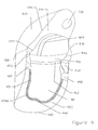
- FIG. 1 there is shown an exploded view of one embodiment of a helmet and facial shield assembly 10 of the instant invention.
- the helmet assembly 10 includes a helmet shell 600, a helmet liner 100, an outer filter protector 500, a filter cover support 300, a headband assembly 175 and a facial shield 400 which comprises a lens 401 and a cuff (or seal) 450.
- the headband 175 is used to seat the helmet 10 on the head of the wearer 590.
- the headband 175 is fairly conventional and is, also, optional. That is, a different head engaging support mechanism can be utilized or it can be omitted, if preferred.
- the headband 175 includes the head-encircling band 176 which is adjustable to comfortably fit the head size of the individual wearer.
- An adjustment latch 177 permits the headband 176 to be shortened or lengthened in a conventional manner.
- the headband 176 includes suitable attachment arms 179 for attachment to the helmet liner 100 by means of suitable fasteners 180 which can be screws, staples, or the like.
- the helmet liner 100 is, typically, formed of a lightweight material, such as polypropylene or LPPE, for example. Helmet liner 100 is configured to conform, generally, to the shape of the upper portion of the wearer's head but to be spaced away from the top of the head of the wearer by the appropriate spaces 101 and 102 (see Figure 3 ) which can be formed in the helmet, foam pads or the like.
- the frontal portion of the helmet liner 100 is designed to span the area between the forehead of the wearer 590 wherein surface 120 acts as the front portion of the headband 175 or is in juxtaposition sufficiently close to minimize airflow therebetween.
- a surface 130 extends to the outer edge 140 of the helmet liner 100 which may attach to the lower perimeter of the helmet shell 600, if so desired.
- the spanning effect may also be accomplished in whole or in part by foam inserts, if so desired.
- a plurality of holes 150 extend upwardly through the surface 130 of the helmet liner 100 to provide for airflow therethrough and toward the contained volume about the face or the wearer 590.
- the helmet liner 100 has an accordion-like area 110 (better seen in Figure 3A ) which permits the helmet liner 100 to flex and better conform to the wearer's head.
- the helmet liner 100 is sufficiently sturdy to support a cooling or air moving mechanism such as a respirator helmet 600 (earlier called "helmet shell”) or the like as known in the prior art.
- a respirator helmet 600 headlier called "helmet shell”
- the respirator helmet liner may be attached to the helmet liner 100 by a snap in groove, 195 around the perimeter of the liner or any other conventional means, but does not form part of the claimed invention.
- a fan covering (not shown) can be joined to or integrally formed to provide a protective and contouring cover for fan mechanism of any conventional type as, for example, described in U.S. Patent Nos. D460,584 and 6,792,944 .
- air flow channels can be defined and maintained around the helmet assembly 10 whereby an optional fan mechanism can provide a cooling and filtered air flow to the wearer of the helmet assembly 10.
- a filter 700 typically, but not limitatively, fabricated of electrostatically charged fibrous plastic material (e.g. melt blown polypropylene) is configured to conform to the outer shape of the helmet shell 600 and is adapted to fit fairly snugly thereto.
- electrostatically charged fibrous plastic material e.g. melt blown polypropylene
- the filter may be so designed as to be self supporting. The level or degree of filtration of air which enters or leaves the helmet shell 600 can be controlled by appropriate selection of the material of the filter 700,
- Filter 700 is, typically, mounted to the helmet shell 600 with a force friction fit and by snaps around the perimeter of the helmet shell 600 as illustrated (in Fig. 1 ) by side and rear snaps 710 and 711.
- any suitable fastener can be utilized.
- the top edge of lens 401 is attached to the perimeter of the helmet shell 600, the helmet liner 100, or the filter cover support 300, if so equipped.
- the filter protector 500 is provided to cover the filter 700.
- the filter protector 500 can be fabricated of a material which is the same as (or similar to) helmet liner 100, if so desired.
- the filter protector 500 prevents damage to the filter 700 and, as well, prevents persons (including the helmet wearer) from touching the possibly contaminated surface of filter 700.
- the filter protector 500 is attached to the helmet shell 600, typically, by a force-fit or any other technique.
- the rear deck (or tail) 187 of the helmet liner 100 engages the rear edge of helmet shell 600 and provides additional stability to the apparatus.
- the facial lens 401 fabricated of an impermeable, flexible and transparent material such as polycarbonate, or the like, is adapted to be mounted to and bear against the outer front surface of filter cover support, as described infra.
- the juxtaposition of the inner surface of the lens 401 and the outer surface of the filter cover support provides a seal there between.
- a sealing means 410 as described infra or other suitable means may be provided to enhance the seal.
- the cuff 450 is fabricated of a sheet of pliant material such as rayon or thin plastic or meltblown polypropylene.
- the cuff 450 also serves as a protective barrier to prevent particulate material from being transmitted to or from the wearer 590 to or from the ambient.
- the cuff 450 is attached to the lens 401 along a seam (also referred to as joinder edge, curved edge and curved end) 425.
- the mid-portion of cuff 450 is adapted to be tucked under the chin of the wearer 590.
- FIG. 3A there is shown an enlarged view of a portion of the view of the apparatus shown in Figure 3 .
- This enlarged view shows the arrangement of the holes 150, and the accordion-like area 110.
- support tabs 452 and 453 are held in close proximity to the extension of liner surface 130.
- the support tabs maintain the upper extensions 461 and 462 of cuff free edge 451 in close proximity to the wearer's head, as better seen in Figure 5 .
- facial shield 400 comprising lens 401 and protective cuff 450 can be joined together as a subassembly and placed over the helmet shell 600, in concert with liner 100 or spanning means to define an enclosed volume about the face of the wearer 590 thereby providing or enhancing the filtering and protecting functions described.
- the M-shaped cuff 450 includes the enlarged portion 460 at the mid-portion thereof. This "bump” or “nose” portion is provided in order to provide a secure engagement under and with the chin of the wearer of the helmet.
- Suitable connectors (or attachments) 403,404 and 405, such as sections of hook-and-loop material, holes for engaging snap posts or an adhesive strip may be applied near the upper edge 402 of lens 401.
- These connectors (or adhesive strip) can be used to attach the upper edge 402 of lens 401 to the front of the helmet liner 100, helmet 600 or filter protector support 300 (see Figures 1 and 4 ).
- a strip 410 of sealing material such as foam, a rubber tube or other compressible strip which can engage the front of the liner 100 or helmet 600 providing an enhanced seal thereto.
- the seal is a thin strip 410 of pretensioned elastic applied flat to lens 401 and adhered along one side to create (see Fig. 7 ) a fixed edge 412 and a free edge 411 such that when the lens 401 is bent the free edge 411 will seek a smaller radius of curvature, with an arc length closer to its untensioned length, than the fixed edge 412. This causes the surface 413 to tend toward perpendicular to the surface of lens 401.
- an inexpensive gasket is produced with a spanning capability equivalent to the width of surface 413.
- the facial shield 400 can be used with many types and shapes of helmets which incorporate a suitable connector or attachment mechanism.
- the cuff 450 is separated from the lens 401 (except at the joinder edge 425). Concurrently, the lens 401 is curved into a generally semi-circular configuration to surround the wearer's head.
- the connectors 403 and 404 (similar connection 405 is seen in Figure 6 ) attached to a counterpart connector on the front of the filter cover support 300 (not shown in Fig. 6 ).
- the lens 401 assumes a curvilinear configuration in front of the face to the wearer 590 of the helmet assembly 10.
- the cuff 450 in particular the nose 460 (see Figures 7A, 7B and 7C ) is placed under the chin of the wearer 590 to enhance the gripping of the chin by the cuff and the protection provided thereby.
- the edge 451 of the cuff 450 otherwise engages the neck and throat area of the wearer 590, as best seen in Figure 5 .
- the cuff 450 also engages the sides of the head of the wearer 590 and forms a protective surface therearound.
- the flexible support tabs 452 and 453 are arranged to cause the cuff 450 to maintain the preferred shape surrounding the head of the wearer 590, as described supra. Specifically they interact with the tension created along the edge 451 by the insertion of the wearers face to draw the upper extension 462 (and similarly 461 shown in Figure 6 ) of the free edge 451 into contact or close proximity of the temple area of the wearers head thus extending away from the joinder edge 425 into abutment with the upper or temporal portion of the head of the wearer 590.
- the optional slots 454 and 455 are provided to accept and engage a portion of the edge of the helmet liner 100, if desired.
- FIG 6 there is shown a perspective view of the lens and cuff attachment to be used with the helmet shell 100 shown in prior Figures 1 , 2 and 3 .
- the lens 401 is fabricated of a thin sheet of transparent polycarbonate (or similar) plastic.
- a suitable thickness is about 0.254 mm (0.01 inches) thick although thicker or thinner materials may be used.
- the cuff 450 is fabricated of a suitably supple material such as but not limited to rayon, meltblown polypropylene, latex rubber or the like and is about 0.254 mm (0.01 inches) thick dependant on the characteristics of the material.
- the lens 401 and cuff 450 are joined together at the curved free edge 425 by any suitable means such as gluing, stitching or the like.
- the free or upper edge 402 of lens 401 is shaped to properly mate with the front edge of the helmet liner 100 and/or filter protector support 300, as described supra.
- the free edge 451 of the cuff 451 in a preferred embodiment, is formed in an undulating, generally, M-shape with nose 460, better seen in Figures 7A, 7B and 7C .
- Support tabs 452 and 453 can be provided at the upper ends of the cuff 450 adjacent to the respective ends of the curved edge or end 425.
- the support tabs 452, 453 permit advantageous fitting of the cuff 450 to helmet.
- the tabs 452 and 453 are flexible about an axis parallel to the flat surface of the tab 452, 453 but less so in other directions.
- Figures 7A, 7B and 7C there are shown additional designs of the shield combination 400 of lens 401 and cuff 450, which are assisting in the appreciation of the invention.
- Figures 7A, 7B and 7C demonstrate the ability of these devices to be manufactured in a flat or two-dimensional configuration which is more easily achieved with automated production equipment.
- the lens 401 includes an adhesive band 408 attached at the upper edge 402 thereof.
- the adhesive band 408 replaces the hook-and-loop connectors 402, 403 and 405, holes 402A, 403A and 405A or other features are used to assist in alignment.
- the adhesive band 408 can be a multiple use adhesive for re-adhering the shield to the helmet, if desired.
- the adhesive band 408 is a tacky material so that the shield 400 can be removed from the helmet and discarded after use.
- the flexible supports 452 and 453 include the slots 454 and 455 therein.
- flexible gores 406 and 407 are included between the ends of the cuff 450 and the support tabs 452 and 452, respectively.
- the flexible gores permit some stretchability or elasticity in the structure of cuff 450.
- the gores can be fabricated of any suitable stretchable material such as spandex or latex rubber.
- FIG 7B there is shown another design of the facial shield 400.
- the lens 401 similar to the lens 401 in Figure 7A in that it includes an adhesive band 408 and/or attachment features 402, 403 and 405 at the edge thereof.
- the nose 460 is provided along the free edge 451 of the cuff 450.
- the cuff 450A has elongated end portions 470 and 471 which extend beyond the edge 402 and band 408 of the lens 401.
- An elastic band (or cord) 480 is affixed to the ends 470 and 471 in any suitable fashion.
- the elastic band 480 can be stretched to pass over the helmet, head and/or nape of the neck of the wearer and then contract to form a reasonably snug but comfortable fit of the cuff 450A to the wearer.
- This structure allows the entire cuff to be made of a less expensive non-stretchable material such as SMS polypropylene or a cellulose non-woven.
- a tie, drawstring or other securing means can be used to secure the helmet/shield apparatus to the wearer.
- the lens 401 and cuff 450 thus, provide a protective barrier for the face of the wearer.
- FIG 7C there is shown another design of the facial shield 400.
- the lens 401 and adhesive band 408 are similar to those shown in Figure 7B .
- the cuff 450A with the elongated ends 470 and 471 is shown.
- the ends 470 and 471 include openings 490 and 491, respectively therethrough.
- the openings (or holes) 490 and 491 can be utilized to engage suitable mounting devices, such as knob 115 shown on the helmet liner 100 in Figur 3 .
- helmet liner 100 Alternatively, a cord, elastic band, or other suitable securing components attached to helmet liner 100 can be utilized, as well.
- the entire cuff 450B can be made of an extremely stretchable material with an elasticity of greater than 300%, such as latex or silicone rubber.
- the free edge of the cuff 450B can assume any shape.
- the support tabs 452 and 453 or features similar to 612 and 613 or 610, 611 and 620 would provide means to draw the free edge into communication with the wearers head. As these materials tend to be expensive or uncomfortable against the wearers face this is considered less desirable.
- the lens and cuff assembly (shield combination )400 may be attached to a hood 800 such as is described in US Patent No. 5,054,480; Bare, et al noted supra.
- the hood 800 is designed for use with a similar helmet structure as previously described.
- the cuff 450 defines a smaller space volume about the face of the wearer which is being easier to restrict contaminant entry thereto.
- the filter protector 300 as described supra is omitted and the hood 800 encloses the wearer's head, as well as the helmet.
- At least a portion 810 of the hood can be constructed of a permeable material such as open cell foam, felt or meltblown polypropylene so as to provide airflow therethrough and into filter 600 (see Figure 1 ).
- the permeable portion 810 may be constructed of an electrostatically charged meltblown polypropylene or other filter media thereby acting as a prefilter for filter 600, or in some instances as a filter in lieu of filter 600.
- the lens and cuff assembly 400 may be attached to a support structure allowing it to form the contained volume about the wearers face with out requiring a ridged supporting structure or helmet.
- lens 400 is similar to previous configurations in that cuff 450C is attached to lens 401 about edge 425, the free edge 451 of cuff 450C contains nose 460, support tabs 452 and 453 and stretchable gores 406 and 407 are included, if so desired.
- An extension 941 to cuff 450C has free edge 947 extending from edge 451 to create a closed profile which encircles the wearer's head.
- Headband 920 is attached to free edge 947 at joinders 946 and 947 by sewing or other conventional means. This arrangement causes the headband to rest against the wearer's forehead thereby stabilizing the hood on the wearer's head.
- a second strap 925 is installed to extend across the top of the wearer's head, if desired.
- a second ply 940 of material is attached to the upper edge 402 of lens 401.
- the second ply is attached to cuff extension 941 along edge 945 by sewing or other conventional means to create a contained volume about the wearers face and head, if desired.
- An opening 950 is provided in cuff extension 942 for attachment of an air supply means.
- the areas 470A respectively, adjacent to the free edge 451 of the cuff 450 may be cut in a pattern of interlocking lines (or strips) which will allow some give or stretch in a normally non-stretchable material such as SMS meltblown polypropylene, cellulose non-woven, or the like as described supra.
- the elastic recovery capability of this patterned area may be enhanced by the adhesion of elastic fibers of hot melt adhesive or the like, if so desired.
Landscapes
- Helmets And Other Head Coverings (AREA)
- Respiratory Apparatuses And Protective Means (AREA)
Claims (11)
- Casque de protection comprenant : une protection faciale (400) comprenant :une première feuille (401) en un matériau qui est imperméable, flexible et transparent,une deuxième feuille (450) en un matériau qui est souple,les première et deuxième feuilles (401, 450) de matériau comportant chacune une première portion de leur périmètre ayant sensiblement la même configuration de bord courbe (425), les premières portions des première et deuxième feuilles (401, 450) de matériau étant jointes entre elles de telle sorte que la protection faciale (400) puisse reposer à plat,les première et deuxième feuilles (401, 450) de matériau comportant chacune une deuxième portion de leur périmètre qui est séparable l'une de l'autre, caractérisé pardes pattes de support souples (452, 453) prévues au niveau des extrémités supérieures de la deuxième feuille (450) à côté des extrémités respectives du bord courbe ou du bord de jonction (425), les pattes de support souples (452, 453) étant agencés de façon à faire en sorte que la deuxième feuille (450) conserve une forme préférée entourant la tête d'un utilisateur (500) en agissant en interaction avec une tension créée le long d'un bord libre (451) de la deuxième feuille (450) par l'insertion du visage de l'utilisateur pour tirer une extension supérieure (462) du bord libre (451) en contact ou à proximité rapprochée de la région de la tempe de la tête de l'utilisateur, s'éloignant ainsi du bord courbe ou du bord de jonction (425) pour venir en butée avec une portion supérieure ou temporale de la tête de l'utilisateur (500).
- Casque selon la revendication 1, dans lequel
la première feuille de matériau (401) a un bord sensiblement droit (402) le long de la deuxième portion. - Casque selon la revendication 1, dans lequel
la deuxième feuille (450) a un bord courbe (451) le long de la deuxième portion (425). - Casque selon la revendication 1, comprenant
une structure de support pour supporter la protection faciale (400). - Casque selon la revendication 4, dans lequel la structure de support comprend des moyens de fixation (179) pour fixer la protection faciale (400) à au moins une section de la structure de support.
- Casque selon la revendication 4, dans lequel
la structure de support comprend une structure de casque (10). - Casque selon la revendication 4, dans lequel
la deuxième portion de la deuxième feuille (450) a une forme générale de "M" ondulé. - Casque selon la revendication 2, dans lequel
une portion de la deuxième feuille (450) adjacente au bord libre (451) est découpée selon un motif en chevrons inter-verrouillé permettant à la portion découpée de s'allonger, dans lequel de préférence
des fibres élastiques sont liées à la portion découpée pour améliorer sa récupération élastique. - Casque selon la revendication 2, dans lequel une portion de la deuxième feuille est élastique.
- Casque selon la revendication 5, dans lequel
la structure de support comprend des plis en accordéon pour améliorer sa souplesse. - Casque selon la revendication 10, dans lequel
la structure de support coopère avec les première et deuxième feuilles de matériau pour définir une région fermée autour du visage de l'utilisateur.
Applications Claiming Priority (1)
| Application Number | Priority Date | Filing Date | Title |
|---|---|---|---|
| US12/313,649 US8453262B2 (en) | 2008-11-24 | 2008-11-24 | Personal environmental protection apparatus |
Publications (3)
| Publication Number | Publication Date |
|---|---|
| EP2189074A2 EP2189074A2 (fr) | 2010-05-26 |
| EP2189074A3 EP2189074A3 (fr) | 2011-10-12 |
| EP2189074B1 true EP2189074B1 (fr) | 2015-01-28 |
Family
ID=41630684
Family Applications (1)
| Application Number | Title | Priority Date | Filing Date |
|---|---|---|---|
| EP09014578.0A Active EP2189074B1 (fr) | 2008-11-24 | 2009-11-23 | Appareil respiratoire |
Country Status (6)
| Country | Link |
|---|---|
| US (1) | US8453262B2 (fr) |
| EP (1) | EP2189074B1 (fr) |
| JP (1) | JP5789892B2 (fr) |
| CN (1) | CN101732807B (fr) |
| CA (1) | CA2683259C (fr) |
| ES (1) | ES2535050T3 (fr) |
Families Citing this family (31)
| Publication number | Priority date | Publication date | Assignee | Title |
|---|---|---|---|---|
| US9271872B2 (en) * | 2008-02-26 | 2016-03-01 | Illinois Tool Works Inc. | Welding helmet air flow barrier |
| US8453262B2 (en) | 2008-11-24 | 2013-06-04 | Pabban Development, Inc. | Personal environmental protection apparatus |
| JP5887850B2 (ja) * | 2011-11-11 | 2016-03-16 | Dicプラスチック株式会社 | ヘルメット |
| US10470505B2 (en) * | 2014-05-07 | 2019-11-12 | Medline Industries, Inc. | Protective apparel system with impervious protection |
| KR101509612B1 (ko) * | 2014-07-11 | 2015-04-09 | 김종기 | 방독면용 외측렌즈 장착기구 |
| US20160066643A1 (en) * | 2014-09-10 | 2016-03-10 | Douglas SQUAIR | Cover assembly for face-shield bracket assembly and safety hat |
| US20180103711A1 (en) * | 2016-03-08 | 2018-04-19 | Mike P. ABRAHAMSON | Helmet with fan |
| CN107581694A (zh) * | 2016-07-06 | 2018-01-16 | 沈阳韩秋平科技有限公司 | 一种用于防尘头罩的波纹管 |
| US10750800B2 (en) | 2018-01-26 | 2020-08-25 | Stryker Corporation | Surgical apparel system |
| WO2020006243A1 (fr) | 2018-06-27 | 2020-01-02 | Stryker Corporation | Système de vêtement de protection doté d'un ensemble lentille |
| US11793261B2 (en) | 2018-10-24 | 2023-10-24 | Stryker Corporation | Surgical helmet assembly having an adjustment mechanism |
| US11547169B2 (en) | 2019-01-25 | 2023-01-10 | Stryker Corporation | Surgical apparel system |
| US10420386B1 (en) | 2019-01-25 | 2019-09-24 | Stryker Corporation | Medical garment including a shield |
| US12295447B2 (en) | 2019-01-25 | 2025-05-13 | Stryker Corporation | Personal protection system including medical garment with a shield |
| US12414591B2 (en) | 2019-05-02 | 2025-09-16 | Stryker Corporation | Surgical helmet assembly with a reconfigurable chin bar |
| USD936905S1 (en) | 2019-07-31 | 2021-11-23 | Stryker Corporation | Surgical hood |
| USD979145S1 (en) | 2019-07-31 | 2023-02-21 | Stryker Corporation | Surgical helmet |
| US11219254B2 (en) | 2020-03-13 | 2022-01-11 | Pabban Development, Inc. | Personal protection system and method |
| CN111450440A (zh) * | 2020-05-20 | 2020-07-28 | 博瑞生物医疗科技(深圳)有限公司 | 一种新型冠状病毒医用防护头盔 |
| PL238257B1 (pl) * | 2020-06-26 | 2021-08-02 | Lubelska Polt | Opaska nadmuchowa |
| US11369155B2 (en) * | 2020-07-24 | 2022-06-28 | Market Union Co., Ltd. | Removable face mask |
| WO2022026737A1 (fr) * | 2020-07-30 | 2022-02-03 | Richard Newbold | Systèmes, dispositifs et/ou procédés de gestion de ventilation d'aéronef |
| EP3967169A1 (fr) * | 2020-09-15 | 2022-03-16 | 3M Innovative Properties Company | Protège-menton, ensemble et kit de pièces correspondants et procédé de modification d'un protège-menton |
| US20220143429A1 (en) * | 2020-11-11 | 2022-05-12 | Pengsuorn Thomas Chea | Face Shield Assembly with Positive Pressure Airflow |
| CA3199911A1 (fr) * | 2020-12-03 | 2022-06-09 | Robert Ranson | Dispositif d'extension de recouvrement de crane pour ecran facial |
| KR102443458B1 (ko) * | 2020-12-08 | 2022-09-16 | 주식회사 오토스윙 | 헤드 커버 결합형 헤드 밴드 |
| US11278750B1 (en) * | 2021-02-17 | 2022-03-22 | Donald Acomb | PAPR frame |
| US11318333B1 (en) | 2021-04-17 | 2022-05-03 | Christopher T. Ellerbrake | Respiratory protection system |
| IL312384A (en) | 2021-10-27 | 2024-06-01 | Pabban Dev Inc | Personal protection system and method |
| KR102465075B1 (ko) * | 2021-12-16 | 2022-11-09 | 대한민국 | Ict기반 다기능 스마트 헬멧 |
| CN115531757B (zh) * | 2022-09-15 | 2023-07-25 | 甘肃省人民医院 | 一种可更换的口鼻部及眼部手术防护系统 |
Family Cites Families (24)
| Publication number | Priority date | Publication date | Assignee | Title |
|---|---|---|---|---|
| US4920960A (en) * | 1987-10-02 | 1990-05-01 | Tecnol, Inc. | Body fluids barrier mask |
| US4805639A (en) | 1987-11-09 | 1989-02-21 | Caresystems, Inc. | Medical cap with face shield |
| US4965887A (en) | 1987-11-12 | 1990-10-30 | John A. Paoluccio | Face protector for splash and spatter protection |
| US4856535A (en) | 1987-11-25 | 1989-08-15 | Forbes Christopher B | Protective face shield |
| US4945574A (en) | 1988-02-09 | 1990-08-07 | Dhl Research And Development Corporation | Protective mask |
| JPH04816U (fr) * | 1989-12-28 | 1992-01-07 | ||
| US5054480A (en) | 1990-06-14 | 1991-10-08 | Bio Medical Devices, Inc. | Personal air filtration and control system |
| US6568392B1 (en) * | 1995-09-11 | 2003-05-27 | 3M Innovative Properties Company | Flat-folded personal respiratory protection devices and processes for preparing same |
| US5711033A (en) | 1995-10-05 | 1998-01-27 | Bio-Medical Devices, Inc. | Air filtration and control system including head gear |
| US5878742A (en) | 1997-09-11 | 1999-03-09 | Figueredo; Joseph P. | Airvisor delivery system |
| US6016805A (en) * | 1998-03-10 | 2000-01-25 | 3M Innovative Properties Company | Face seal for respirator |
| US6394090B1 (en) * | 1999-02-17 | 2002-05-28 | 3M Innovative Properties Company | Flat-folded personal respiratory protection devices and processes for preparing same |
| CN2401206Y (zh) * | 1999-12-14 | 2000-10-18 | 李勇 | 一次性防溅护目口罩 |
| USD460584S1 (en) | 2001-05-07 | 2002-07-16 | Pabban Development, Inc. | Helmet with air flow rib structure |
| US6792944B1 (en) | 2002-02-26 | 2004-09-21 | Pabban Development Inc. | Air filtration and control system including headgear |
| CA2422025A1 (fr) * | 2002-03-12 | 2003-09-12 | Bombardier Inc. | Casque avec masque respiratoire a passages d'air |
| CN2623269Y (zh) * | 2003-05-06 | 2004-07-07 | 山西新华化工厂 | 防护口罩 |
| US7055521B1 (en) * | 2003-08-13 | 2006-06-06 | Johnson Ronald A | Ventilated mask for outdoor use |
| US6918141B2 (en) | 2003-09-23 | 2005-07-19 | Pabbon Development, Inc. | Protective headgear system |
| US7703456B2 (en) * | 2003-12-18 | 2010-04-27 | Kimberly-Clark Worldwide, Inc. | Facemasks containing an anti-fog / anti-glare composition |
| JP3113958U (ja) * | 2005-06-22 | 2005-09-22 | 健史 望月 | めがねマスク |
| US20070277294A1 (en) * | 2006-05-30 | 2007-12-06 | Green Lawrence J | Protective headgear system with filter protector |
| US8020552B2 (en) * | 2007-02-26 | 2011-09-20 | Microtek Medical, Inc. | Helmets and methods of making and using the same |
| US8453262B2 (en) | 2008-11-24 | 2013-06-04 | Pabban Development, Inc. | Personal environmental protection apparatus |
-
2008
- 2008-11-24 US US12/313,649 patent/US8453262B2/en active Active
-
2009
- 2009-10-19 CA CA2683259A patent/CA2683259C/fr active Active
- 2009-11-20 JP JP2009265166A patent/JP5789892B2/ja active Active
- 2009-11-23 EP EP09014578.0A patent/EP2189074B1/fr active Active
- 2009-11-23 ES ES09014578.0T patent/ES2535050T3/es active Active
- 2009-11-24 CN CN200910225003.4A patent/CN101732807B/zh active Active
Also Published As
| Publication number | Publication date |
|---|---|
| EP2189074A3 (fr) | 2011-10-12 |
| JP2010121263A (ja) | 2010-06-03 |
| CA2683259A1 (fr) | 2010-05-24 |
| HK1144564A1 (zh) | 2011-02-25 |
| JP5789892B2 (ja) | 2015-10-07 |
| EP2189074A2 (fr) | 2010-05-26 |
| CN101732807A (zh) | 2010-06-16 |
| ES2535050T3 (es) | 2015-05-04 |
| US20100125934A1 (en) | 2010-05-27 |
| US8453262B2 (en) | 2013-06-04 |
| CN101732807B (zh) | 2016-04-20 |
| CA2683259C (fr) | 2016-10-04 |
Similar Documents
| Publication | Publication Date | Title |
|---|---|---|
| EP2189074B1 (fr) | Appareil respiratoire | |
| EP1862199B1 (fr) | Système de protection de la tête avec protège-filtre | |
| EP0468188B1 (fr) | Système de filtration et de contrÔle d'air | |
| JP5320457B2 (ja) | コンバーチブル型の頭部被覆部材を包含するレスピレータシステム | |
| CN100496320C (zh) | 保护性头盔系统 | |
| EP3061502B1 (fr) | Casque de protection respiratoire non motorisé et masque avec une prévention contre une vitre embueé | |
| US20210298387A1 (en) | Protective mask accessories | |
| KR20230023805A (ko) | 안면 커버 시스템 | |
| US20220110386A1 (en) | Full face protective shield | |
| CN211960990U (zh) | 一种防雾型呼吸面罩 | |
| KR102003183B1 (ko) | 안면마스크 | |
| HK1144564B (en) | Respirator apparatus | |
| US20220369737A1 (en) | Medical Face Protective Device With Optimum Protection | |
| WO2023187627A1 (fr) | Dispositif de protection de visage médical à protection optimale | |
| GB2597479A (en) | Protective hood | |
| HK1110818B (en) | Protective headgear system with filter protector | |
| WO2014138058A1 (fr) | Ensemble protecteur pour la tête présentant une pièce extérieure amovible résistante aux impacts |
Legal Events
| Date | Code | Title | Description |
|---|---|---|---|
| PUAI | Public reference made under article 153(3) epc to a published international application that has entered the european phase |
Free format text: ORIGINAL CODE: 0009012 |
|
| AK | Designated contracting states |
Kind code of ref document: A2 Designated state(s): AT BE BG CH CY CZ DE DK EE ES FI FR GB GR HR HU IE IS IT LI LT LU LV MC MK MT NL NO PL PT RO SE SI SK SM TR |
|
| AX | Request for extension of the european patent |
Extension state: AL BA RS |
|
| PUAL | Search report despatched |
Free format text: ORIGINAL CODE: 0009013 |
|
| AK | Designated contracting states |
Kind code of ref document: A3 Designated state(s): AT BE BG CH CY CZ DE DK EE ES FI FR GB GR HR HU IE IS IT LI LT LU LV MC MK MT NL NO PL PT RO SE SI SK SM TR |
|
| AX | Request for extension of the european patent |
Extension state: AL BA RS |
|
| RIC1 | Information provided on ipc code assigned before grant |
Ipc: A42B 3/28 20060101ALI20110905BHEP Ipc: A42B 3/22 20060101AFI20110905BHEP |
|
| 17P | Request for examination filed |
Effective date: 20120329 |
|
| 17Q | First examination report despatched |
Effective date: 20120703 |
|
| GRAP | Despatch of communication of intention to grant a patent |
Free format text: ORIGINAL CODE: EPIDOSNIGR1 |
|
| INTG | Intention to grant announced |
Effective date: 20140806 |
|
| GRAS | Grant fee paid |
Free format text: ORIGINAL CODE: EPIDOSNIGR3 |
|
| GRAA | (expected) grant |
Free format text: ORIGINAL CODE: 0009210 |
|
| AK | Designated contracting states |
Kind code of ref document: B1 Designated state(s): AT BE BG CH CY CZ DE DK EE ES FI FR GB GR HR HU IE IS IT LI LT LU LV MC MK MT NL NO PL PT RO SE SI SK SM TR |
|
| REG | Reference to a national code |
Ref country code: GB Ref legal event code: FG4D |
|
| REG | Reference to a national code |
Ref country code: CH Ref legal event code: EP |
|
| REG | Reference to a national code |
Ref country code: IE Ref legal event code: FG4D |
|
| REG | Reference to a national code |
Ref country code: DE Ref legal event code: R096 Ref document number: 602009029193 Country of ref document: DE Effective date: 20150312 |
|
| REG | Reference to a national code |
Ref country code: AT Ref legal event code: REF Ref document number: 707846 Country of ref document: AT Kind code of ref document: T Effective date: 20150315 |
|
| REG | Reference to a national code |
Ref country code: ES Ref legal event code: FG2A Ref document number: 2535050 Country of ref document: ES Kind code of ref document: T3 Effective date: 20150504 |
|
| REG | Reference to a national code |
Ref country code: AT Ref legal event code: MK05 Ref document number: 707846 Country of ref document: AT Kind code of ref document: T Effective date: 20150128 |
|
| REG | Reference to a national code |
Ref country code: NL Ref legal event code: VDEP Effective date: 20150128 |
|
| REG | Reference to a national code |
Ref country code: LT Ref legal event code: MG4D |
|
| PG25 | Lapsed in a contracting state [announced via postgrant information from national office to epo] |
Ref country code: LT Free format text: LAPSE BECAUSE OF FAILURE TO SUBMIT A TRANSLATION OF THE DESCRIPTION OR TO PAY THE FEE WITHIN THE PRESCRIBED TIME-LIMIT Effective date: 20150128 Ref country code: HR Free format text: LAPSE BECAUSE OF FAILURE TO SUBMIT A TRANSLATION OF THE DESCRIPTION OR TO PAY THE FEE WITHIN THE PRESCRIBED TIME-LIMIT Effective date: 20150128 Ref country code: FI Free format text: LAPSE BECAUSE OF FAILURE TO SUBMIT A TRANSLATION OF THE DESCRIPTION OR TO PAY THE FEE WITHIN THE PRESCRIBED TIME-LIMIT Effective date: 20150128 Ref country code: NO Free format text: LAPSE BECAUSE OF FAILURE TO SUBMIT A TRANSLATION OF THE DESCRIPTION OR TO PAY THE FEE WITHIN THE PRESCRIBED TIME-LIMIT Effective date: 20150428 Ref country code: BG Free format text: LAPSE BECAUSE OF FAILURE TO SUBMIT A TRANSLATION OF THE DESCRIPTION OR TO PAY THE FEE WITHIN THE PRESCRIBED TIME-LIMIT Effective date: 20150428 Ref country code: SE Free format text: LAPSE BECAUSE OF FAILURE TO SUBMIT A TRANSLATION OF THE DESCRIPTION OR TO PAY THE FEE WITHIN THE PRESCRIBED TIME-LIMIT Effective date: 20150128 |
|
| PG25 | Lapsed in a contracting state [announced via postgrant information from national office to epo] |
Ref country code: IS Free format text: LAPSE BECAUSE OF FAILURE TO SUBMIT A TRANSLATION OF THE DESCRIPTION OR TO PAY THE FEE WITHIN THE PRESCRIBED TIME-LIMIT Effective date: 20150528 Ref country code: NL Free format text: LAPSE BECAUSE OF FAILURE TO SUBMIT A TRANSLATION OF THE DESCRIPTION OR TO PAY THE FEE WITHIN THE PRESCRIBED TIME-LIMIT Effective date: 20150128 Ref country code: PL Free format text: LAPSE BECAUSE OF FAILURE TO SUBMIT A TRANSLATION OF THE DESCRIPTION OR TO PAY THE FEE WITHIN THE PRESCRIBED TIME-LIMIT Effective date: 20150128 Ref country code: AT Free format text: LAPSE BECAUSE OF FAILURE TO SUBMIT A TRANSLATION OF THE DESCRIPTION OR TO PAY THE FEE WITHIN THE PRESCRIBED TIME-LIMIT Effective date: 20150128 Ref country code: LV Free format text: LAPSE BECAUSE OF FAILURE TO SUBMIT A TRANSLATION OF THE DESCRIPTION OR TO PAY THE FEE WITHIN THE PRESCRIBED TIME-LIMIT Effective date: 20150128 Ref country code: GR Free format text: LAPSE BECAUSE OF FAILURE TO SUBMIT A TRANSLATION OF THE DESCRIPTION OR TO PAY THE FEE WITHIN THE PRESCRIBED TIME-LIMIT Effective date: 20150429 |
|
| REG | Reference to a national code |
Ref country code: DE Ref legal event code: R097 Ref document number: 602009029193 Country of ref document: DE |
|
| PG25 | Lapsed in a contracting state [announced via postgrant information from national office to epo] |
Ref country code: CZ Free format text: LAPSE BECAUSE OF FAILURE TO SUBMIT A TRANSLATION OF THE DESCRIPTION OR TO PAY THE FEE WITHIN THE PRESCRIBED TIME-LIMIT Effective date: 20150128 Ref country code: DK Free format text: LAPSE BECAUSE OF FAILURE TO SUBMIT A TRANSLATION OF THE DESCRIPTION OR TO PAY THE FEE WITHIN THE PRESCRIBED TIME-LIMIT Effective date: 20150128 Ref country code: SK Free format text: LAPSE BECAUSE OF FAILURE TO SUBMIT A TRANSLATION OF THE DESCRIPTION OR TO PAY THE FEE WITHIN THE PRESCRIBED TIME-LIMIT Effective date: 20150128 Ref country code: EE Free format text: LAPSE BECAUSE OF FAILURE TO SUBMIT A TRANSLATION OF THE DESCRIPTION OR TO PAY THE FEE WITHIN THE PRESCRIBED TIME-LIMIT Effective date: 20150128 Ref country code: RO Free format text: LAPSE BECAUSE OF FAILURE TO SUBMIT A TRANSLATION OF THE DESCRIPTION OR TO PAY THE FEE WITHIN THE PRESCRIBED TIME-LIMIT Effective date: 20150128 |
|
| REG | Reference to a national code |
Ref country code: FR Ref legal event code: PLFP Year of fee payment: 7 |
|
| PLBE | No opposition filed within time limit |
Free format text: ORIGINAL CODE: 0009261 |
|
| STAA | Information on the status of an ep patent application or granted ep patent |
Free format text: STATUS: NO OPPOSITION FILED WITHIN TIME LIMIT |
|
| 26N | No opposition filed |
Effective date: 20151029 |
|
| PG25 | Lapsed in a contracting state [announced via postgrant information from national office to epo] |
Ref country code: SI Free format text: LAPSE BECAUSE OF FAILURE TO SUBMIT A TRANSLATION OF THE DESCRIPTION OR TO PAY THE FEE WITHIN THE PRESCRIBED TIME-LIMIT Effective date: 20150128 |
|
| PG25 | Lapsed in a contracting state [announced via postgrant information from national office to epo] |
Ref country code: MC Free format text: LAPSE BECAUSE OF FAILURE TO SUBMIT A TRANSLATION OF THE DESCRIPTION OR TO PAY THE FEE WITHIN THE PRESCRIBED TIME-LIMIT Effective date: 20150128 Ref country code: LU Free format text: LAPSE BECAUSE OF FAILURE TO SUBMIT A TRANSLATION OF THE DESCRIPTION OR TO PAY THE FEE WITHIN THE PRESCRIBED TIME-LIMIT Effective date: 20151123 |
|
| REG | Reference to a national code |
Ref country code: CH Ref legal event code: PL |
|
| PG25 | Lapsed in a contracting state [announced via postgrant information from national office to epo] |
Ref country code: LI Free format text: LAPSE BECAUSE OF NON-PAYMENT OF DUE FEES Effective date: 20151130 Ref country code: CH Free format text: LAPSE BECAUSE OF NON-PAYMENT OF DUE FEES Effective date: 20151130 |
|
| REG | Reference to a national code |
Ref country code: IE Ref legal event code: MM4A |
|
| PG25 | Lapsed in a contracting state [announced via postgrant information from national office to epo] |
Ref country code: IE Free format text: LAPSE BECAUSE OF NON-PAYMENT OF DUE FEES Effective date: 20151123 |
|
| REG | Reference to a national code |
Ref country code: FR Ref legal event code: PLFP Year of fee payment: 8 |
|
| PG25 | Lapsed in a contracting state [announced via postgrant information from national office to epo] |
Ref country code: HU Free format text: LAPSE BECAUSE OF FAILURE TO SUBMIT A TRANSLATION OF THE DESCRIPTION OR TO PAY THE FEE WITHIN THE PRESCRIBED TIME-LIMIT; INVALID AB INITIO Effective date: 20091123 Ref country code: SM Free format text: LAPSE BECAUSE OF FAILURE TO SUBMIT A TRANSLATION OF THE DESCRIPTION OR TO PAY THE FEE WITHIN THE PRESCRIBED TIME-LIMIT Effective date: 20150128 |
|
| PG25 | Lapsed in a contracting state [announced via postgrant information from national office to epo] |
Ref country code: CY Free format text: LAPSE BECAUSE OF FAILURE TO SUBMIT A TRANSLATION OF THE DESCRIPTION OR TO PAY THE FEE WITHIN THE PRESCRIBED TIME-LIMIT Effective date: 20150128 |
|
| PG25 | Lapsed in a contracting state [announced via postgrant information from national office to epo] |
Ref country code: TR Free format text: LAPSE BECAUSE OF FAILURE TO SUBMIT A TRANSLATION OF THE DESCRIPTION OR TO PAY THE FEE WITHIN THE PRESCRIBED TIME-LIMIT Effective date: 20150128 Ref country code: MT Free format text: LAPSE BECAUSE OF FAILURE TO SUBMIT A TRANSLATION OF THE DESCRIPTION OR TO PAY THE FEE WITHIN THE PRESCRIBED TIME-LIMIT Effective date: 20150128 |
|
| REG | Reference to a national code |
Ref country code: FR Ref legal event code: PLFP Year of fee payment: 9 |
|
| PG25 | Lapsed in a contracting state [announced via postgrant information from national office to epo] |
Ref country code: MK Free format text: LAPSE BECAUSE OF FAILURE TO SUBMIT A TRANSLATION OF THE DESCRIPTION OR TO PAY THE FEE WITHIN THE PRESCRIBED TIME-LIMIT Effective date: 20150128 Ref country code: PT Free format text: LAPSE BECAUSE OF FAILURE TO SUBMIT A TRANSLATION OF THE DESCRIPTION OR TO PAY THE FEE WITHIN THE PRESCRIBED TIME-LIMIT Effective date: 20150128 |
|
| REG | Reference to a national code |
Ref country code: DE Ref legal event code: R082 Ref document number: 602009029193 Country of ref document: DE Representative=s name: KILBURN & STRODE LLP, NL |
|
| PGFP | Annual fee paid to national office [announced via postgrant information from national office to epo] |
Ref country code: ES Payment date: 20231211 Year of fee payment: 15 |
|
| PGFP | Annual fee paid to national office [announced via postgrant information from national office to epo] |
Ref country code: IT Payment date: 20231110 Year of fee payment: 15 |
|
| PGFP | Annual fee paid to national office [announced via postgrant information from national office to epo] |
Ref country code: BE Payment date: 20231121 Year of fee payment: 15 |
|
| REG | Reference to a national code |
Ref country code: BE Ref legal event code: MM Effective date: 20241130 |
|
| PG25 | Lapsed in a contracting state [announced via postgrant information from national office to epo] |
Ref country code: IT Free format text: LAPSE BECAUSE OF NON-PAYMENT OF DUE FEES Effective date: 20241123 |
|
| PG25 | Lapsed in a contracting state [announced via postgrant information from national office to epo] |
Ref country code: BE Free format text: LAPSE BECAUSE OF NON-PAYMENT OF DUE FEES Effective date: 20241130 |
|
| REG | Reference to a national code |
Ref country code: ES Ref legal event code: FD2A Effective date: 20260107 |
|
| PGFP | Annual fee paid to national office [announced via postgrant information from national office to epo] |
Ref country code: DE Payment date: 20251022 Year of fee payment: 17 |
|
| PGFP | Annual fee paid to national office [announced via postgrant information from national office to epo] |
Ref country code: GB Payment date: 20251016 Year of fee payment: 17 |
|
| PGFP | Annual fee paid to national office [announced via postgrant information from national office to epo] |
Ref country code: FR Payment date: 20251023 Year of fee payment: 17 |
|
| PG25 | Lapsed in a contracting state [announced via postgrant information from national office to epo] |
Ref country code: ES Free format text: LAPSE BECAUSE OF NON-PAYMENT OF DUE FEES Effective date: 20241124 |