EP2189114A1 - Vorrichtung zur Fixierung der weiblichen Brust für die diagnostische Bildgebung und Intervention - Google Patents
Vorrichtung zur Fixierung der weiblichen Brust für die diagnostische Bildgebung und Intervention Download PDFInfo
- Publication number
- EP2189114A1 EP2189114A1 EP09154868A EP09154868A EP2189114A1 EP 2189114 A1 EP2189114 A1 EP 2189114A1 EP 09154868 A EP09154868 A EP 09154868A EP 09154868 A EP09154868 A EP 09154868A EP 2189114 A1 EP2189114 A1 EP 2189114A1
- Authority
- EP
- European Patent Office
- Prior art keywords
- breast
- patient
- fixation
- force
- fixing
- Prior art date
- Legal status (The legal status is an assumption and is not a legal conclusion. Google has not performed a legal analysis and makes no representation as to the accuracy of the status listed.)
- Withdrawn
Links
- 210000000481 breast Anatomy 0.000 title claims abstract description 48
- 238000002059 diagnostic imaging Methods 0.000 title description 2
- 210000000038 chest Anatomy 0.000 claims description 10
- 210000000779 thoracic wall Anatomy 0.000 claims description 4
- 238000002560 therapeutic procedure Methods 0.000 description 3
- 239000000463 material Substances 0.000 description 2
- 230000006978 adaptation Effects 0.000 description 1
- 238000001574 biopsy Methods 0.000 description 1
- 230000006835 compression Effects 0.000 description 1
- 238000007906 compression Methods 0.000 description 1
- 238000002591 computed tomography Methods 0.000 description 1
- 238000003745 diagnosis Methods 0.000 description 1
- 238000006073 displacement reaction Methods 0.000 description 1
- 239000013013 elastic material Substances 0.000 description 1
- 230000002349 favourable effect Effects 0.000 description 1
- 239000012530 fluid Substances 0.000 description 1
- 238000003384 imaging method Methods 0.000 description 1
- 238000012544 monitoring process Methods 0.000 description 1
- 210000002445 nipple Anatomy 0.000 description 1
- 230000005855 radiation Effects 0.000 description 1
- 238000005070 sampling Methods 0.000 description 1
- 230000000087 stabilizing effect Effects 0.000 description 1
- 230000001225 therapeutic effect Effects 0.000 description 1
Images
Classifications
-
- A—HUMAN NECESSITIES
- A61—MEDICAL OR VETERINARY SCIENCE; HYGIENE
- A61B—DIAGNOSIS; SURGERY; IDENTIFICATION
- A61B6/00—Apparatus or devices for radiation diagnosis; Apparatus or devices for radiation diagnosis combined with radiation therapy equipment
- A61B6/04—Positioning of patients; Tiltable beds or the like
- A61B6/0407—Supports, e.g. tables or beds, for the body or parts of the body
- A61B6/0414—Supports, e.g. tables or beds, for the body or parts of the body with compression means
Definitions
- the invention relates to a device for fixing the female breast, applicable in diagnostic imaging and interventional therapy.
- a device for fixing the breast serves to fix the breast in a position which is advantageous and reproducible for the imaging, diagnostic examination.
- This fixation may also be used for fixation in a tissue sampling (biopsy) or other type of suspicious tissue or therapy diagnosis.
- X-ray equipment To examine the female breast, various devices, such as X-ray equipment or CT scanners are known. Such a CT scanner is for example in the US 2006/0094950 A1 disclosed.
- a CT scanner Under a couch, on which a patient to be examined lies, there is an X-ray device with a rotating gantry which has an X-ray tube and a detector.
- the breast of the patient to be examined projects through an opening in the couch into the beam path of the x-ray device.
- the breast to be examined In order to generate constant conditions during the examination, the breast to be examined is pressed upwards with a stamp and brought into a predefined shape. By moving the stamp an adaptation to different breast sizes is possible.
- the compression of the breast is a breast wall near examination not possible.
- Another device for stabilizing the breast of the patient is in the US Pat.
- No. 6,418,188 B1 disclosed.
- a gummed tissue cup is slipped over the breast and pulled away from the patient by a cord. As a result, the breast is compressed in diameter and stretched in length. With this device, no exactly reproducible position and shape of the breast can be produced.
- vacuum fixation systems as in the EP 1864611 A1 disclosed, the breast is pulled by vacuum into a shell. This negative pressure can affect the fluid distribution in the tissue. Again, with hard shells an invasive diagnostic or therapeutic measure such as tissue removal is not possible. The size of the shell must be adapted to the size of the breast, making it difficult to handle.
- the object of the invention is to fix the breast of a patient during a diagnostic examination and / or a therapeutic procedure in a reproducible position and to detach it as far as possible from the thorax without negatively influencing the position and presentation of the tissue structures of the breast.
- a device according to the invention for fixing a female breast 31 of a patient 30 in a medical examination device comprises at least one elastic annular fixation 110, 114.
- This device tightly encloses the breast at its attachment to the chest wall. Furthermore, this fixation exerts a force in one direction away from the patient. As a result, the breast can be subtracted slightly from the chest wall. This makes it easier to To capture the entire area of the breast, for example with an X-ray machine.
- a net 113 is provided, which is attached to the elastic annular fixation 110, 114.
- This net also encloses the rest of the breast closely.
- a force is now exerted on the net in the direction away from the patient.
- the elastic annular fixation 110, 114 comprises a plurality of fixing loop pull cords. These can be adjusted individually and are preferably arranged at an angle of 90 degrees to each other. As a result, each paired against each other Fixierschlingen-drawstrings can be braced against each other.
- At least one motor is provided, which contracts the elastic annular fixation 110, 114.
- At least one motor is provided which pulls the elastic annular fixation 110, 114 or the net 113 away from the patient.
- the motor is connected to a force measuring and control device which shuts off the motor when a predetermined force is reached.
- the motor could be controlled via a control loop so that it exerts a constant force.
- Another aspect of the invention relates to an X-ray machine, in particular a CT scanner with a fixing device as described above.
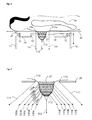
- FIG. 1 a device according to the invention is shown in an X-ray machine in lateral section.
- the patient 30 is stored on the patient couch 20.
- a spiral computer tomography gantry 10 The patient's breast 31 hangs through the breast section 21 into the receiving area of this gantry.
- the gantry 10 has within the gantry housing 29 an x-ray tube 15, which generates the fan beam 16. The radiation of this fan of rays penetrates the breast 31 and is captured by the detector 14.
- the gantry rotates through the Gantrycraft 13. Simultaneously with the rotation, a displacement in the direction of the patient, here in the vertical direction, is carried out via the gantry lifting drive 11, so that the breast is scanned spirally.
- the breast is fixed in a fixing device, which comprises at least one fixing loop 114 and a net 113.
- the fixing loop pull cords 111 the at least one fixing loop 114 can be reduced in size.
- the net 113 can be pulled away from the patient by the net pull cord 112.
- FIG. 2 is a particularly flexible adjustable device according to the invention shown.
- additional tensioning cords 119a to 119j are provided, each attached to the net and embracing the breast at its periphery.
- pull rings 120a-120e are formed.
- the circumference of the corresponding tension ring and thus also of the net can be reduced, thus increasing the pressure on the chest.
- the circumference of the net on the pull ring 120a can be reduced close to the patient. Reducing the circumference of the pull ring 120e near the nipple allows the tension cords 119e and 119f.
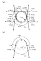
- FIG. 3 shows a plan view of the breast fixation device, as shown in FIG. 1 and in FIG. 2 is shown.
- deflection eyelets 115a, 115b, 115c, 115d are mounted within the breast section 21 of the patient table 20 .
- the fixation loop pull cords are preferably made of an elastic material, which in turn is so stiff that each retains the approximate shape of the cords as shown, even in the relaxed state.
- rings 116 are still provided which hold together the different fixing loops pull cords. By this Fixierschlingen pull cords, a circle 114 is approximately formed.
- the fixation loop pull cords are tightened in the direction of the arrow in a first step, so that the diameter of the circle 114 adapts to the size of the breast and closely surrounds it.
- the network attached to the loop of fixation loops in the form of a circle is then pulled away from the patient.
- the invention can also be realized with a single Fixierschlingen-Zugschnüre this must enclose the entire chest. It is more favorable to use two fixation loop pull cords arranged on opposite sides of the breast.
- the device shown here with four Fixierschlingen-Zugschnüren allows a particularly good fixation and a uniform pressure of the cords to the chest.
- FIG. 4 shows a detail of the plan view of the breast fixation device. Only one fixation loop pull cord 111b is shown here. The other fixation loop pull cords have been omitted for clarity.
- the fixation loop pull cord 111b is passed through the rings 116 around the chest. Through the rings 116 and other Fixierschlingen pull cords are guided so that they stabilize each other. Instead of the rings 116 also any other connecting parts can be used, which hold together the individual cords loosely together. In principle, it is also possible to attach to these rings again more pull cords, which pull these rings away from the chest. As a result, a bias on the Fixierschlingen-Zugschnüre be exercised.
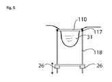
- FIG. 5 shows a further variant of the invention.
- the breast 31 is enclosed by an elastic fixation ring 110.
- This fixation ring includes, for example, an elastic plastic material or a rubber material.
- the elastic fixing ring 110 is attached to a positioning unit, here comprising the two guide rods 118 and the lifting drive 26.
- at least one force gauge 117 is provided, which monitors the tension of the elastic fixing ring or the force exerted on it, so that no excessive force is exerted on the breast.
- the elastic fixation ring 110 is contracted in a first step, so that it adapts to the diameter of the breast and firmly encloses it.
- this elastic fixation ring 110 is pulled away by the patient by means of the positioning unit.
- a net can also be pulled over the breast, similar to that described in the first embodiment of the invention. In this case, then advantageously the network itself is pulled away in the direction of the patient.
Landscapes
- Health & Medical Sciences (AREA)
- Life Sciences & Earth Sciences (AREA)
- Medical Informatics (AREA)
- Engineering & Computer Science (AREA)
- Radiology & Medical Imaging (AREA)
- Biomedical Technology (AREA)
- Biophysics (AREA)
- Nuclear Medicine, Radiotherapy & Molecular Imaging (AREA)
- Optics & Photonics (AREA)
- Pathology (AREA)
- Physics & Mathematics (AREA)
- High Energy & Nuclear Physics (AREA)
- Heart & Thoracic Surgery (AREA)
- Molecular Biology (AREA)
- Surgery (AREA)
- Animal Behavior & Ethology (AREA)
- General Health & Medical Sciences (AREA)
- Public Health (AREA)
- Veterinary Medicine (AREA)
- Apparatus For Radiation Diagnosis (AREA)
Abstract
Description
- Die Erfindung betrifft eine Vorrichtung zur Fixierung der weiblichen Brust, anwendbar bei der diagnostischen Bildaufnahme und der interventionellen Therapie. Eine derartige Vorrichtung dient zur Fixierung der Brust in einer für die bildgebende, diagnostische Untersuchung vorteilhaften und reproduzierbaren Position. Diese Fixierung kann darüber hinaus auch für eine Fixierung bei einer Gewebeprobenentnahme (Biopsie) oder einer anderen Art der Diagnose eines verdächtigen Gewebes oder einer Therapie genutzt werden.
- Zur Untersuchung der weiblichen Brust sind verschiedene Geräte, wie Röntgengeräte oder auch CT-Scanner bekannt. Ein solcher CT-Scanner ist beispielsweise in der
US 2006/0094950 A1 offenbart. Unter einer Liege, auf der eine zu untersuchende Patientin liegt, befindet sich eine Röntgenvorrichtung mit einer rotierenden Gantry, welche eine Röntgenröhre und einen Detektor aufweist. Die zu untersuchende Brust der Patientin ragt durch eine Öffnung in der Liege in den Strahlengang der Röntgenvorrichtung. Um nun während der Untersuchung konstante Verhältnisse zu erzeugen, wird die zu untersuchende Brust mit einem Stempel nach oben gedrückt und in eine vordefinierte Form gebracht. Durch eine Verschiebung des Stempels ist eine Anpassung an unterschiedliche Brustgrößen möglich. Allerdings ist durch die Kompression der Brust eine brustwandnahe Untersuchung nicht möglich. Eine andere Vorrichtung zur Stabilisierung der Brust der Patientin ist in derUS 6,418,188 B1 offenbart. Ein Becher aus gummiartigem Gewebe wird über die Brust gestülpt und mittels einer Schnur von der Patientin weggezogen. Dadurch wird die Brust im Durchmesser komprimiert und in die Länge gezogen. Mit dieser Vorrichtung ist keine exakt reproduzierbare Lage und Form der Brust herstellbar. Durch Vakuumfixierungssysteme wie in derEP 1864611 A1 offenbart, wird die Brust durch Unterdruck in eine Schale gezogen. Dieser Unterdruck kann die Flüssigkeitsverteilung im Gewebe beeinflussen. Auch hier ist bei harten Schalen eine invasive diagnostische oder therapeutische Maßnahme wie Gewebeentnahme nicht möglich. Die Größe der Schale muss an die Größe der Brust angepasst werden, was die Handhabbarkeit erschwert. - Der Erfindung liegt die Aufgabe zu Grunde, die Brust einer Patientin während einer diagnostischen Untersuchung und/oder einem therapeutischen Eingriff in einer reproduzierbaren Position zu fixieren und möglichst weit vom Brustkorb zu lösen, ohne die Lage und Darstellung der Gewebestrukturen der Brust negativ zu beeinflussen.
- Diese Aufgabe wird durch eine Vorrichtung nach Anspruch 1 gelöst. Vorteilhafte Ausgestaltungen der Erfindung sind in den Unteransprüchen angegeben.
- Eine erfindungsgemäße Vorrichtung zur Fixierung einer weiblichen Brust 31 einer Patientin 30 in einem medizinischen Untersuchungsgerät umfasst wenigstens eine elastische ringförmige Fixierung 110, 114. Diese umschließt die Brust an ihrem Ansatz an der Brustwand eng. Weiterhin wird durch diese Fixierung eine Kraft in einer Richtung von der Patientin weg ausgeübt. Dadurch kann die Brust geringfügig von der Brustwand abgezogen werden. Somit ist es einfacher möglich, den gesamten Bereich der Brust beispielsweise mit einem Röntgengerät zu erfassen.
- In einer besonders vorteilhaften Ausgestaltung der Erfindung ist ein Netz 113 vorgesehen, welches an der elastischen ringförmigen Fixierung 110, 114 befestigt ist. Auch dieses Netz umschließt die übrige Brust eng. Hier wird nun eine Kraft auf das Netz in Richtung von der Patientin weg ausgeübt. Somit ergibt sich ein Zug auf das Netz selbst und auf die damit verbundene elastische ringförmige Fixierung.
- Es vorteilhaft wenn die elastische ringförmige Fixierung 110, 114 mehrere Fixierschlingen-Zugschnüre umfasst. Diese können einzelne eingestellt werden und sind vorzugsweise in einem Winkel von 90 Grad zueinander angeordnet. Dadurch können jeweils paarweise gegeneinander angeordnete Fixierschlingen-Zugschnüre gegeneinander verspannt werden.
- Vorteilhafterweise ist wenigstens ein Motor vorgesehen, welche die elastische ringförmige Fixierung 110, 114 zusammenzieht.
- Weiterhin ist es vorteilhaft, wenn wenigstens ein Motor vorgesehen ist, der die elastische ringförmige Fixierung 110, 114 beziehungsweise das Netz 113 von der Patientin weg zieht.
- Besonders vorteilhaft ist es, wenn der Motor mit einer Kraftmess- und Steuereinrichtung verbunden ist, welche den Motor beim Erreichen einer vorgegebenen Kraft abschaltet. Alternativ hierzu könnte der Motor über eine Regelschleife derart geregelt werden, dass er eine konstante Kraft ausübt.
- Ein weiterer Aspekt der Erfindung betrifft ein Röntgengerät, insbesondere einen CT Scanner mit einer Fixiervorrichtung wie oben beschrieben.
- Die Erfindung wird nachstehend ohne Beschränkung des allgemeinen Erfindungsgedankens anhand von Ausführungsbeispielen unter Bezugnahme auf die Zeichnungen exemplarisch beschrieben.
-
Figur 1 zeigt eine erfindungsgemäße Vorrichtung -
Figur 2 zeigt eine besonders flexibel einstellbare erfindungsgemäße Vorrichtung -
Figur 3 zeigt eine Draufsicht auf die Brust-Fixiervorrichtung. -
Figur 4 zeigt ein Detail der Draufsicht auf die Brust-Fixiervorrichtung. -
Figur 5 zeigt eine weitere Variante der Erfindung - In
Figur 1 ist eine erfindungsgemäße Vorrichtung in einem Röntgengerät im seitlichen Schnitt dargestellt. Die Patientin 30 ist auf der Patientenliege 20 gelagert. Unterhalb der Patientin befindet sich eine Spiral-Computertomographen Gantry 10. Die Brust 31 der Patientin hängt durch den Brustausschnitt 21 in den Aufnahmebereich dieser Gantry. Die Gantry 10 hat innerhalb des Gantrygehäuses 29 eine Röntgenröhre 15, welche den Strahlenfächer 16 erzeugt. Die Strahlung dieses Strahlenfächers durchdringt die Brust 31 und wird von dem Detektor 14 aufgefangen. Um die gesamte Brust abzubilden, lässt die Gantry sich durch das Gantrydrehlager 13 drehen. Gleichzeitig mit der Drehung wird über den Gantryhubantrieb 11 eine Verschiebung in Richtung der Patientin, hier in vertikaler Richtung, durchgeführt, so dass die Brust spiralförmig abgetastet wird. Erfindungsgemäß wird die Brust in einer Fixiervorrichtung fixiert, welche wenigstens eine Fixierschlinge 114 sowie ein Netz 113 umfasst. Mittels der Fixierschlingen-Zugschnüre 111 kann die wenigstens eine Fixierschlinge 114 verkleinert werden. - Weiterhin kann das Netz 113 durch die Netz-Zugschnur 112 von der Patientin weggezogen werden.
- In
Figur 2 ist eine besonders flexibel einstellbare Vorrichtung entsprechend der Erfindung dargestellt. Hier sind zusätzliche Spannschnüre 119a bis 119j vorgesehen, welche jeweils am Netz befestigt sind und die Brust an ihrem Umfang umfassen. Dadurch werden Zugringe 120a -120e gebildet. Durch Zug an einer Spannschnur in Pfeilrichtung kann hier der Umfang des entsprechenden Zugringes und somit auch des Netzes verringert und somit der Druck auf die Brust erhöht werden. So kann beispielsweise durch gleichzeitigen Zug auf die Schnüre 119a und 119j der Umfang des Netzes am Zugring 120a nahe an der Patientin verringert werden. Eine Verringerung des Umfangs des Zugringes 120e in der Nähe der Brustwarze erlauben die Spannschnüre 119e und 119f. Der Umfang der dazwischen liegenden Zugringe 120b, 120c, 120d mit den anderen hier dargestellten Spannschnüren 119b, 119i; 119c, 119h; 119d, 119g verändern. In dieser Figur sind beispielhaft 5 Paare von Spannschnüren dargestellt. Grundsätzlich ist aber jede andere Anzahl von Spannschnüren realisierbar. Ebenso ist es möglich, für einen Spannring anstatt einem Paar von Spannschnüren jede andere Anzahl von Spannschnüren, beispielsweise eine Spannschnur oder auch vier Spannschnüre einzusetzen. -
Figur 3 zeigt eine Draufsicht auf die Brust-Fixiervorrichtung, wie sie inFigur 1 und inFigur 2 dargestellt ist. Innerhalb des Brustausschnitts 21 der Patientenliege 20 sind Umlenkösen 115a, 115b, 115c, 115d angebracht. Diese führen die Fixierschlingen-Zugschnüre 111a, 111b, 111c, 111d. Die Fixierschlingen-Zugschnüre bestehen vorzugsweise aus einem elastischen Material, welches wiederum so steif ist, dass jedes auch im spannungsfreien Zustand die ungefähre Form der Schnüre wie dargestellt beibehält. Weiterhin sind noch Ringe 116 vorgesehen, welche die verschiedenen Fixierschlingen Zugschnüre zusammenhalten. Durch diese Fixierschlingen-Zugschnüre wird näherungsweise ein Kreis 114 gebildet. - Zur Fixierung werden in einem ersten Schritt die Fixierschlingen-Zugschnüre in Pfeilrichtung angezogen, so dass sich der Durchmesser des Kreises 114 an die Größe der Brust anpasst und diese eng umschließt. In einem zweiten Schritt wird dann das an den Fixierschlingen-Zugschnüren in Form eines Kreises befestigte Netz von der Patientin weggezogen. Anstelle der hier dargestellten vier Fixierschlingen-Zugschnüre ist auch jede andere Zahl von Fixierschlingen-Zugschnüren möglich. Grundsätzlich kann die Erfindung auch mit einer einzigen Fixierschlingen-Zugschnüre realisiert werden hierzu muss sie die gesamte Brust umschließen. Günstiger ist es, zwei Fixierschlingen-Zugschnüre, welche auf gegenüberliegenden Seiten der Brust angeordnet sind, zu verwenden. Die hier dargestellte Vorrichtung mit vier Fixierschlingen-Zugschnüren ermöglicht eine besonders gute Fixierung und einem gleichmäßigen Andruck der Schnüre an die Brust.
-
Figur 4 zeigt ein Detail der Draufsicht auf die Brust-Fixiervorrichtung. Es ist hier nur eine Fixierschlingen-Zugschnur 111b dargestellt. Die anderen Fixierschlingen-Zugschnüre wurden der Übersichtlichkeit halber weggelassen. Die Fixierschlingen-Zugschnur 111b wird durch die Ringe 116 um die Brust geführt. Durch die Ringe 116 werden auch andere Fixierschlingen-Zugschnüre geführt, so dass diese sich gegenseitig stabilisieren. Anstelle der Ringe 116 können auch beliebige andere Verbindungsteile eingesetzt werden, welche die einzelnen Schnüre lose aneinander zusammenhalten. Grundsätzlich ist es auch möglich, an diesen Ringen wieder weitere Zugschnüre zu befestigen, welche diese Ringe von der Brust weg ziehen. Dadurch kann eine Vorspannung auf die Fixierschlingen-Zugschnüre ausgeübt werden. Weiterhin kann damit die ganze Vorrichtung auf einfache Weise wieder geöffnet werden, sobald die Zugkraft von den Fixierschlingen-Zugschnüren nicht mehr besteht. Um eine automatische Öffnung zu erreichen, könnten auch Zugfedern an diesen Ringen angreifen, so dass diese nach außen, von der Brust weg gezogen werden. Um eine saubere Führung der Fixierschlingen-Zugschnüre zu erreichen, sind noch weitere Umlenkösen 115b und 115d vorgesehen. Diese ermöglichen beispielsweise eine Umlenkung der Fixierschlingen-Zugschnüre von der Patientin weg und aus dem Arbeitsbereich der Gantry. Eine solche Umlenkung nach unten ist in derFigur 1 dargestellt. -
Figur 5 zeigt eine weitere Variante der Erfindung. Hierbei wird die Brust 31 durch einen elastischen Fixierungsring 110 umschlossen. Dieser Fixierungsring umfasst beispielsweise ein elastisches Kunststoffmaterial oder auch ein Gummimaterial. Der elastische Fixierungsring 110 ist an einer Positioniereinheit, hier umfassend die beiden Führungsstangen 118 sowie dem Hubantrieb 26 befestigt. Weiterhin ist wenigstens ein Kraftmesser 117 vorgesehen, welcher die Spannung des elastischen Fixierungsring oder die auf diesen ausgeübte Kraft überwacht, so dass auf die Brust keine zu große Kraft ausgeübt wird. Zur Fixierung der Brust wird in einem ersten Schritt der elastische Fixierungsring 110 zusammengezogen, so dass er sich dem Durchmesser der Brust anpasst und diese fest umschließt. Dann wird in einem zweiten Schritt dieser elastische Fixierungsring 110 von der Patientin mittels der Positioniereinheit weggezogen. Auch hier findet bevorzugt eine Überwachung der Kraft statt. Grundsätzlich ist möglich, das zusammenziehen, beziehungsweise das wegziehen von der Patientin so lange durchzuführen, bis eine maximale Kraft erreicht ist. Eine andere Alternative wäre eine konstante Kraftregelung, bei der beispielsweise der Hubantrieb 26 permanent eine konstante Kraft auf die Brust ausübt. Bei dieser Ausführungsform kann auch ein Netz über die Brust gezogen werden, ähnlich wie dies bei der ersten Ausführungsform der Erfindung beschrieben ist. In diesem Falle wird dann vorteilhafterweise das Netz selbst in Richtung von der Patientin weggezogen. -
- 10
- Gantry
- 11
- Gantryhubantrieb
- 13
- Gantrydrehlager
- 14
- Detektor
- 15
- Röntgenröhre
- 16
- Strahlenfächer
- 20
- Patientenliege
- 21
- Brustausschnitt
- 24
- Gantryaufhängung
- 26
- Hubantrieb
- 30
- Patientin
- 31
- Brust
- 110
- elastischer Fixierungsring
- 111
- Fixierschlinge Zugschnur
- 112
- Netz-Zugschnur
- 113
- Netz
- 114
- Fixierschlingen - Kreis
- 115
- Umlenköse
- 116
- Ring
- 117
- Kraftmesser
- 118
- Führungsstange
- 119
- Spannschnur
- 120
- Zugring
Claims (7)
- Vorrichtung zur Fixierung einer weiblichen Brust (31) einer Patientin (30) in einem medizinischen Untersuchungsgerät umfassend eine elastische ringförmige Fixierung (110, 114), welche die Brust an ihrem Ansatz an der Brustwand eng umschließt und auf die eine Kraft in einer Richtung von der Patientin weg ausgeübt wird.
- Vorrichtung nach Anspruch 1,
dadurch gekennzeichnet, dass
ein Netz (113) vorgesehen ist, welches an der elastischen ringförmigen Fixierung (110, 114) befestigt ist, und die übrige Brust eng umschließt, wobei eine Kraft auf das Netz in Richtung von der Patientin weg ausgeübt wird, um die Brust zu komprimieren und von der Brustwand abzuziehen. - Vorrichtung nach Anspruch 1 oder 2,
dadurch gekennzeichnet, dass
die elastische ringförmige Fixierung (110, 114) mehrere Fixierschlingen-Zugschnüre (111a, 111b, 111c, 111d) umfasst. - Vorrichtung nach einem der vorhergehenden Ansprüche,
dadurch gekennzeichnet, dass
wenigstens ein Motor vorgesehen ist, welcher die elastische ringförmige Fixierung (110, 114) zusammenzieht. - Vorrichtung nach einem der vorhergehenden Ansprüche,
dadurch gekennzeichnet, dass
wenigstens ein Motor vorgesehen ist, welcher die elastische ringförmige Fixierung (110, 114) und/oder das Netz (113) von der Patientin weg zieht. - Vorrichtung nach Anspruch 4 oder 5,
dadurch gekennzeichnet, dass
der wenigstens eine Motor mit einer Kraftmess- und Steuereinrichtung verbunden ist, welche den Motor beim Erreichen einer vorgegebenen Kraft abschaltet oder mit einer Regelschleife über den Motor eine konstante Kraft ausübt. - Röntgengerät, insbesondere CT-Scanner mit einer Vorrichtung zur Fixierung einer weiblichen Brust (31) einer Patientin (30) entsprechend einem der vorhergehenden Ansprüche.
Applications Claiming Priority (1)
| Application Number | Priority Date | Filing Date | Title |
|---|---|---|---|
| DE102008058587 | 2008-11-22 |
Publications (1)
| Publication Number | Publication Date |
|---|---|
| EP2189114A1 true EP2189114A1 (de) | 2010-05-26 |
Family
ID=40846425
Family Applications (1)
| Application Number | Title | Priority Date | Filing Date |
|---|---|---|---|
| EP09154868A Withdrawn EP2189114A1 (de) | 2008-11-22 | 2009-03-11 | Vorrichtung zur Fixierung der weiblichen Brust für die diagnostische Bildgebung und Intervention |
Country Status (2)
| Country | Link |
|---|---|
| US (1) | US20100128843A1 (de) |
| EP (1) | EP2189114A1 (de) |
Cited By (1)
| Publication number | Priority date | Publication date | Assignee | Title |
|---|---|---|---|---|
| DE102010052603A1 (de) * | 2010-11-25 | 2012-05-31 | Artemis Imaging Gmbh | Patientenliege |
Families Citing this family (9)
| Publication number | Priority date | Publication date | Assignee | Title |
|---|---|---|---|---|
| US20100080349A1 (en) * | 2008-09-29 | 2010-04-01 | Mir Medical Imaging Research Holding Gmbh | Modular System for Diagnosis and Surgical Operation on a Breast |
| DE102008049711A1 (de) * | 2008-09-30 | 2010-04-15 | Siemens Aktiengesellschaft | Lagerungsvorrichtung, Patientenlagerungstisch und medizinisches Gerät |
| DE102013113276A1 (de) * | 2013-11-29 | 2015-06-03 | Hubert Noras | Patientenliege für die NMR-Mammographie |
| US9326739B2 (en) * | 2014-04-28 | 2016-05-03 | Cheryl A. Galambos McLaughlin | Mammogram table |
| US10603003B2 (en) * | 2016-04-14 | 2020-03-31 | Dedicating2Imaging, LLC | CT systems for imaging of the breast |
| CN113509650A (zh) * | 2021-07-14 | 2021-10-19 | 河南省肿瘤医院 | 一种胸部肿瘤治疗用定位板 |
| JP7327849B1 (ja) | 2022-02-08 | 2023-08-16 | 隆太郎 和田 | X線を良く透過させて散乱を低減する医療用テーブル |
| WO2023153345A1 (ja) * | 2022-02-08 | 2023-08-17 | 隆太郎 和田 | 被ばくと防護負荷を低減する防護機器・器具 |
| DE102022207880A1 (de) * | 2022-07-29 | 2024-02-01 | Siemens Healthcare Gmbh | Brustfixierungselement |
Citations (5)
| Publication number | Priority date | Publication date | Assignee | Title |
|---|---|---|---|---|
| EP0435837A1 (de) * | 1989-11-23 | 1991-07-03 | Planmed Oy | Verfahren und Vorrichtung zur Regelung der Bewegung, Verschiebung eines Röntgenmammographiegeräts |
| US6418188B1 (en) | 2001-06-14 | 2002-07-09 | Juanita L. Broadnax | Radiation breast cup and method |
| US20050070817A1 (en) * | 2003-09-30 | 2005-03-31 | Mueller Richard L. | Lavage assist device |
| US20060094950A1 (en) | 1999-11-18 | 2006-05-04 | Ruola Ning | Apparatus and method for cone beam computed tomography breast imaging |
| EP1864611A1 (de) | 2005-04-01 | 2007-12-12 | Keizi Shibuya | Brustuntersuchungssystem |
Family Cites Families (44)
| Publication number | Priority date | Publication date | Assignee | Title |
|---|---|---|---|---|
| US4015836A (en) * | 1975-07-31 | 1977-04-05 | General Electric Company | Mammography table |
| US4709382A (en) * | 1984-11-21 | 1987-11-24 | Picker International, Inc. | Imaging with focused curved radiation detectors |
| US5415169A (en) * | 1989-11-21 | 1995-05-16 | Fischer Imaging Corporation | Motorized mammographic biopsy apparatus |
| US5569266A (en) * | 1991-03-11 | 1996-10-29 | Fischer Imaging Corporation | Magnetic resonance imaging device useful for guiding a medical instrument |
| US5273435B1 (en) * | 1992-07-16 | 1995-12-05 | Wisconsin Med College Inc | Tumor localization phantom |
| US5386447A (en) * | 1992-09-23 | 1995-01-31 | Fischer Imaging Corporation | Mammographic screening and biopsy apparatus |
| US5490513A (en) * | 1992-09-28 | 1996-02-13 | Fonar Corporation | Multiple patient breast scanning on a magnetic resonance imaging apparatus |
| JPH07303633A (ja) * | 1994-05-11 | 1995-11-21 | Mitsubishi Electric Corp | X線乳房撮影装置 |
| US5528043A (en) * | 1995-04-21 | 1996-06-18 | Thermotrex Corporation | X-ray image sensor |
| US5609827A (en) * | 1995-05-02 | 1997-03-11 | Beekley Corporation | Biopsy specimen container |
| US5757878A (en) * | 1996-08-16 | 1998-05-26 | Analogic Corporation | Detector arrangement for x-ray tomography system |
| US6358246B1 (en) * | 1999-06-25 | 2002-03-19 | Radiotherapeutics Corporation | Method and system for heating solid tissue |
| US6242743B1 (en) * | 1998-08-11 | 2001-06-05 | Mosaic Imaging Technology, Inc. | Non-orbiting tomographic imaging system |
| JP2000116631A (ja) * | 1998-10-16 | 2000-04-25 | Toshiba Corp | X線診断装置 |
| JP3866431B2 (ja) * | 1999-02-17 | 2007-01-10 | 株式会社東芝 | X線ct装置 |
| US6684097B1 (en) * | 1999-04-22 | 2004-01-27 | University Of Miami | Intraoperative monitoring of temperature-induced tissue changes with a high-resolution digital x-ray system during thermotherapy |
| US6480565B1 (en) * | 1999-11-18 | 2002-11-12 | University Of Rochester | Apparatus and method for cone beam volume computed tomography breast imaging |
| US6463122B1 (en) * | 2000-08-21 | 2002-10-08 | Bio-Imaging Resource, Inc. | Mammography of computer tomography for imaging and therapy |
| US6516045B2 (en) * | 2001-05-04 | 2003-02-04 | The Regents Of The University Of California | Device and method for determining proportions of body materials |
| US6674835B2 (en) * | 2001-10-12 | 2004-01-06 | General Electric Co. | Methods and apparatus for estimating a material composition of an imaged object |
| US6671975B2 (en) * | 2001-12-10 | 2004-01-06 | C. William Hennessey | Parallel kinematic micromanipulator |
| DE10207623B4 (de) * | 2002-02-22 | 2004-05-06 | Siemens Ag | Verfahren für die Computertomographie sowie Computertomographie (CT)-Gerät |
| US20040254461A1 (en) * | 2002-03-20 | 2004-12-16 | Ackerman William H. | Acoustic beam shaping by pulse power modulation at constant amplitude |
| US7065393B2 (en) * | 2002-07-11 | 2006-06-20 | Cedara Software Corp. | Apparatus, system and method of calibrating medical imaging systems |
| US20040082856A1 (en) * | 2002-07-16 | 2004-04-29 | Alfred E. Mann Institute For Biomedical Engineering, University Of Southern California | Support bra for ultrasonic breast scanner |
| US6904119B2 (en) * | 2002-10-02 | 2005-06-07 | Shimadzu Corporation | Radiographic apparatus |
| US7809422B2 (en) * | 2002-11-08 | 2010-10-05 | Art Advanced Research Technologies Inc. | Method and apparatus for optical imaging |
| US6982424B2 (en) * | 2003-06-02 | 2006-01-03 | Ge Medical Systems Global Technology Company, Llc | X-ray and CT image detector |
| US7291841B2 (en) * | 2003-06-16 | 2007-11-06 | Robert Sigurd Nelson | Device and system for enhanced SPECT, PET, and Compton scatter imaging in nuclear medicine |
| DE102004042790A1 (de) * | 2004-09-03 | 2006-03-09 | Siemens Ag | Röntgeneinrichtung |
| CA2588904A1 (en) * | 2004-12-02 | 2006-06-08 | Smith & Nephew, Inc. | Radio frequency identification for medical devices |
| US7564945B2 (en) * | 2005-02-11 | 2009-07-21 | University Of Florida Research Foundation, Inc. | System including computed tomography device for image guided treatment |
| US20070064867A1 (en) * | 2005-09-20 | 2007-03-22 | Hansen Timothy B | Apparatus and method to acquire data for reconstruction of images pertaining to functional and anatomical structure of the breast |
| US7742796B2 (en) * | 2005-10-25 | 2010-06-22 | General Electric Company | Breast immobilization device and method of imaging the breast |
| WO2007111669A2 (en) * | 2005-12-22 | 2007-10-04 | Visen Medical, Inc. | Combined x-ray and optical tomographic imaging system |
| CN101370429A (zh) * | 2006-01-17 | 2009-02-18 | 成象诊断系统公司 | 具有可变患者定位功能的激光成像设备 |
| US7871406B2 (en) * | 2006-08-04 | 2011-01-18 | INTIO, Inc. | Methods for planning and performing thermal ablation |
| US20080037703A1 (en) * | 2006-08-09 | 2008-02-14 | Digimd Corporation | Three dimensional breast imaging |
| US7715523B2 (en) * | 2006-09-28 | 2010-05-11 | Lafferty Peter R | System and apparatus for rapid stereotactic breast biopsy analysis |
| JP4857070B2 (ja) * | 2006-10-11 | 2012-01-18 | キヤノン株式会社 | 乳房撮影用x線ct装置 |
| US20080221443A1 (en) * | 2007-03-07 | 2008-09-11 | Ritchie Paul G | Integrated Imaging and Biopsy System with Ancillary Device Authentication |
| US7597104B2 (en) * | 2007-03-23 | 2009-10-06 | Zheng Mike Q | Method and device for immobilization of the human breast in a prone position for radiotherapy |
| US7453978B1 (en) * | 2007-06-25 | 2008-11-18 | University Of Tennessee Research Foundation | Variable resolution x-ray CT detector with multi-axis tilt |
| US20090080604A1 (en) * | 2007-08-23 | 2009-03-26 | Fischer Medical Technologies, Inc. | Computed tomography breast imaging and biopsy system |
-
2009
- 2009-03-11 EP EP09154868A patent/EP2189114A1/de not_active Withdrawn
- 2009-03-11 US US12/401,906 patent/US20100128843A1/en not_active Abandoned
Patent Citations (5)
| Publication number | Priority date | Publication date | Assignee | Title |
|---|---|---|---|---|
| EP0435837A1 (de) * | 1989-11-23 | 1991-07-03 | Planmed Oy | Verfahren und Vorrichtung zur Regelung der Bewegung, Verschiebung eines Röntgenmammographiegeräts |
| US20060094950A1 (en) | 1999-11-18 | 2006-05-04 | Ruola Ning | Apparatus and method for cone beam computed tomography breast imaging |
| US6418188B1 (en) | 2001-06-14 | 2002-07-09 | Juanita L. Broadnax | Radiation breast cup and method |
| US20050070817A1 (en) * | 2003-09-30 | 2005-03-31 | Mueller Richard L. | Lavage assist device |
| EP1864611A1 (de) | 2005-04-01 | 2007-12-12 | Keizi Shibuya | Brustuntersuchungssystem |
Cited By (1)
| Publication number | Priority date | Publication date | Assignee | Title |
|---|---|---|---|---|
| DE102010052603A1 (de) * | 2010-11-25 | 2012-05-31 | Artemis Imaging Gmbh | Patientenliege |
Also Published As
| Publication number | Publication date |
|---|---|
| US20100128843A1 (en) | 2010-05-27 |
Similar Documents
| Publication | Publication Date | Title |
|---|---|---|
| EP2168484B1 (de) | Röntgengerät zur Brustuntersuchung mit einer in eine Patientenliege integrierten Gantry | |
| DE102011007065B4 (de) | Empfangsspule und Lokalspule für Magnetresonanzanwendungen | |
| DE202011004071U1 (de) | Kompressionsplatte für Tomosynthese | |
| DE102012101142A1 (de) | Verfahren zur Erfassung der Morphologie einer Brust | |
| DE102012204814B4 (de) | Ein zusammenklappbares Kompressionsgerät und Röntgengerät | |
| WO2011138294A1 (de) | Kompressionsplatte für tomosynthese | |
| DE60015389T2 (de) | Gerät zur kompression der nackenwirbelsäule zur medizinischen bildgebung | |
| EP2642926A1 (de) | Strahlenschutzvorrichtung | |
| DE102018216365A1 (de) | Umhüllung für eine MR-Lokalspule | |
| DE10146915B4 (de) | Vefahren und Bildgebungsgerät für eine 3D-Untersuchung am Patienten in aufrechter oder teilweise aufrechter Körperhaltung | |
| EP3223699B1 (de) | Patientenliege für eine kernresonanztomographie-untersuchung | |
| DE102008011157B4 (de) | Medizinisches Röntgensystem | |
| EP2919654B1 (de) | Röntgenologischer arbeitsplatz | |
| DE102011083837B4 (de) | Medizinische Bildgebungsvorrichtung mit einer Druckkammer zur Dämpfung von Vibrationen | |
| DE102015219520A1 (de) | Tomographieanlage und Verfahren für großvolumige 3D-Aufnahmen | |
| DE102010040956B4 (de) | Vorrichtung für einen Tunnel einer Gantry eines bildgebenden medizinischen Gerätes | |
| EP2964087B1 (de) | Patientenliege für die nmr-mammographie | |
| DE102011078677A1 (de) | Medizinisches Röntgengerät | |
| DE112019007825T5 (de) | Struktur eines Endoskops | |
| DE202015105111U1 (de) | HF-Spule für MR-Messungen in einem oralen Bereich und HF-Spulensystem | |
| DE202015000499U1 (de) | Röntgengerät mit C-Arm und dessen Strahlungsschutzvorrichtung | |
| EP2623029B1 (de) | Hilfsvorrichtung zur Untersuchung eines Hüftgelenks | |
| DE102012209692B3 (de) | Verfahren zum Betrieb einer Computertomographieanlage und Computertomographieanlage | |
| WO2016074829A1 (de) | Vorrichtung und verfahren für ein diagnosegerät | |
| DE10122311A1 (de) | Vorrichtung zur ferngesteuerten Navigation medizinscher Instrumente im Körper von Patienten während gleichzeitiger computertomographischer (CT-)Untersuchung |
Legal Events
| Date | Code | Title | Description |
|---|---|---|---|
| PUAI | Public reference made under article 153(3) epc to a published international application that has entered the european phase |
Free format text: ORIGINAL CODE: 0009012 |
|
| AK | Designated contracting states |
Kind code of ref document: A1 Designated state(s): AT BE BG CH CY CZ DE DK EE ES FI FR GB GR HR HU IE IS IT LI LT LU LV MC MK MT NL NO PL PT RO SE SI SK TR |
|
| AX | Request for extension of the european patent |
Extension state: AL BA RS |
|
| 17P | Request for examination filed |
Effective date: 20101126 |
|
| AKX | Designation fees paid |
Designated state(s): AT BE BG CH CY CZ DE DK EE ES FI FR GB GR HR HU IE IS IT LI LT LU LV MC MK MT NL NO PL PT RO SE SI SK TR |
|
| D17P | Request for examination filed (deleted) | ||
| REG | Reference to a national code |
Ref country code: DE Ref legal event code: 8566 |
|
| STAA | Information on the status of an ep patent application or granted ep patent |
Free format text: STATUS: THE APPLICATION IS DEEMED TO BE WITHDRAWN |
|
| 18D | Application deemed to be withdrawn |
Effective date: 20101127 |