EP2189142A2 - Cadre de ressort et corps de ressort destinés au soutien d'un matelas, par exemple - Google Patents
Cadre de ressort et corps de ressort destinés au soutien d'un matelas, par exemple Download PDFInfo
- Publication number
- EP2189142A2 EP2189142A2 EP09014090A EP09014090A EP2189142A2 EP 2189142 A2 EP2189142 A2 EP 2189142A2 EP 09014090 A EP09014090 A EP 09014090A EP 09014090 A EP09014090 A EP 09014090A EP 2189142 A2 EP2189142 A2 EP 2189142A2
- Authority
- EP
- European Patent Office
- Prior art keywords
- spring
- spring body
- frame according
- spring frame
- elastic
- Prior art date
- Legal status (The legal status is an assumption and is not a legal conclusion. Google has not performed a legal analysis and makes no representation as to the accuracy of the status listed.)
- Withdrawn
Links
Images



Classifications
-
- A—HUMAN NECESSITIES
- A61—MEDICAL OR VETERINARY SCIENCE; HYGIENE
- A61G—TRANSPORT, PERSONAL CONVEYANCES OR ACCOMMODATION SPECIALLY ADAPTED FOR PATIENTS OR DISABLED PERSONS; OPERATING TABLES OR CHAIRS; CHAIRS FOR DENTISTRY; FUNERAL DEVICES
- A61G7/00—Beds specially adapted for nursing; Devices for lifting patients or disabled persons
- A61G7/05—Parts, details or accessories of beds
- A61G7/057—Arrangements for preventing bed-sores or for supporting patients with burns, e.g. mattresses specially adapted therefor
- A61G7/0573—Arrangements for preventing bed-sores or for supporting patients with burns, e.g. mattresses specially adapted therefor with mattress frames having alternately movable parts
-
- A—HUMAN NECESSITIES
- A61—MEDICAL OR VETERINARY SCIENCE; HYGIENE
- A61G—TRANSPORT, PERSONAL CONVEYANCES OR ACCOMMODATION SPECIALLY ADAPTED FOR PATIENTS OR DISABLED PERSONS; OPERATING TABLES OR CHAIRS; CHAIRS FOR DENTISTRY; FUNERAL DEVICES
- A61G2203/00—General characteristics of devices
- A61G2203/30—General characteristics of devices characterised by sensor means
- A61G2203/34—General characteristics of devices characterised by sensor means for pressure
-
- A—HUMAN NECESSITIES
- A61—MEDICAL OR VETERINARY SCIENCE; HYGIENE
- A61G—TRANSPORT, PERSONAL CONVEYANCES OR ACCOMMODATION SPECIALLY ADAPTED FOR PATIENTS OR DISABLED PERSONS; OPERATING TABLES OR CHAIRS; CHAIRS FOR DENTISTRY; FUNERAL DEVICES
- A61G7/00—Beds specially adapted for nursing; Devices for lifting patients or disabled persons
- A61G7/05—Parts, details or accessories of beds
- A61G7/057—Arrangements for preventing bed-sores or for supporting patients with burns, e.g. mattresses specially adapted therefor
- A61G7/05715—Arrangements for preventing bed-sores or for supporting patients with burns, e.g. mattresses specially adapted therefor with modular blocks, or inserts, with layers of different material
Definitions
- the invention relates to a spring frame and a spring body for supporting z.
- a mattress especially for nursing beds and domestic beds, but also z.
- a cushion for upholstered furniture and motor vehicle seats or an unpadded edition for example, in light vehicle seats and training equipment for rehabilitation.
- beds and upholstered furniture have a spring frame with steel springs or a wooden slatted base on which a mattress, or a cushion rests.
- a spring frame with steel springs or a wooden slatted base on which a mattress, or a cushion rests.
- This is basically an air mattress.
- the invention is therefore based on the object to provide a spring frame available that allows a pneumatic, well-ventilated storage with a relatively flat structure.
- the above object is achieved in that are mounted on a supporting base pneumatic spring body having an elastic sheath and total or in groups on at least one flexible pressure distribution element are resilient, at least one spring body provided with a valve means gas inlet and / or - has outlet. On the pressure distribution element, a mattress, a cushion or an unpadded pad can be placed.
- the pneumatic spring body replace or supplement the steel springs or resilient wooden slats of the known spring frame, wherein in a particular case a large number of relatively small or different sized, pneumatic spring body can be provided which preferably contain air as gas.
- a pneumatic bearing which can optionally provide a uniform pressure distribution or different pressure zones. Both the spaces between the pneumatic spring bodies and via passageways can be provided for ventilation. Because of the advantageous pneumatic spring characteristics of the spring frame sufficient as a support a relatively thin, well ventilated mattress or padding, which can also have zones of different spring stiffness, such. B. in the EP 01 126 837 A described mattress.
- a pressure distribution element is selected in an embodiment, for. B. in the form of a strong knitted or woven fabric, leather or plastic film, which simultaneously meets the requirements of an unpadded edition, so that they can be omitted.
- Such spring frame are z. B. in vehicle seats and exercise equipment, especially in rehabilitation, used, possibly also with a treadmill as a pressure distribution element and / or edition.
- the elastic shell of the pneumatic spring body is preferably designed so that even in case of failure of the gas or air pressure a certain comfort due to the mechanical spring properties of the elastic sheaths is maintained.
- the spring properties can be selected by selecting the material, eg. As polyurethane (PU) or other suitable thermoplastic, different wall thicknesses, the design of the elastic shell, z. B. in the form of a cylinder or truncated cone with or without folding, affect the void volume and the nature of the valve device.
- a connecting line between the cavities of certain spring bodies or groups of spring bodies increases the compressed gas volume under load of a spring body and leads under otherwise identical conditions to a flatter spring characteristic. Such a characteristic is usually perceived as pleasant.
- Throttles or throttle valves in the valve means of the pneumatic spring body can be provided when the pneumatic spring body to respond with delay to load changes.
- Check valves are used to automatically replenish air leaks when the elastic sheath of a pneumatic spring body expands again after loading.
- the new spring frame is also suitable for active control of the spring properties, at least part of the pneumatic spring body.
- they can be connected to a common pressure line and common signal and control lines and provided with pressure sensors.
- Controllable inlet and vent valves are expediently actuated by piezoelectric elements and can be controlled by a processor via a bus system.
- Such a control system can accommodate the varying weight of patients and respond very quickly to movements of a person in bed.
- An especially suitable for use in the spring frame according to the invention pneumatic spring body which is mainly intended for large loads, has an elastic sheath in the outer shape of one or more superimposed in the loading direction superimposed, preferably round cushions, each with the inner cavities adjacent Cushion are delimited by a single or multi-layer partition, but communicate via a connection opening.
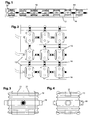
- Fig. 1 one of several rows of pneumatic spring body 10 is shown, one of which in 3 and 4 shown in larger scale as a single item.
- the spring body 10 are fixed on a base 12 in the form of a plate, batten or spring bar and connected to each other at the top by a highly flexible pressure distribution element 14.
- the spring body 10 are connected to the adjacent spring bodies in the series and in each case also with the adjacent spring bodies of the adjacent rows by connecting lines 16.
- the air or other gas containing inner cavities of the spring body 10 communicate with each other.
- the pressure increase is much lower and the spring characteristic correspondingly flatter than in an arrangement of spring bodies which are not connected to each other via connecting lines 16.
- the spring body 10 can individually, in groups or in total, possibly including connecting lines 16, produced in two halves and then welded in a lying transverse to the central longitudinal axis, middle part plane.
- valve devices may be arranged, for. As throttles or throttle valves to delay under load of a spring body 10, the displacement of air from the cavity.
- pressure relief valves could be used at individual points or generally.
- controllable valves can be used, which, for. B. be programmatically controlled so that depending on the load distribution and thus recognizable position or sitting position of a person closed certain spring body and thereby hardened and brought by opening the valve connecting them and possibly vented or slightly more pressurized air.
- each individual or defined groups of spring bodies 10 may preferably also be such that all the spring body 10 in series to a bypassed at all compressed air line in each case via a z.
- B. actuatable by piezoelectric elements control valve can be connected, wherein the control is done by a bus system and the control valves in series connecting signal line. To this Way can be set in each of the spring body 10, a certain pressure and thus a certain spring characteristic.
- the z. B. cooperate with a projection in the upper region of the shell or a fixed portion of the flexible pressure distribution element 14, limit the travel.
- spring bodies 10 Before discussing further forms of spring bodies 10 below, it should be pointed out that it is expedient to fix the spring bodies 10 at least relative to one another, if possible also relative to the base 12 and the pressure distributor element 14.
- the in Fig. 1 to 4 shown spring body formed both on its underside and on its upper side with two depressions 21, in which on the base 12 and on the flexible pressure distribution element 14 mounted, nozzle-shaped projections engage.
- the connecting lines 16, despite existing flexibility and tensile and compressive load in the longitudinal direction can be made relatively rigid, so that they also represent mechanically effective couplings between the spring bodies 10.
- spring body 10 extends through the middle of its inner cavity through a ventilation duct 22 which has at the bottom and top connection to through holes in the base 12 and in the pressure distribution element 14.
- a ventilation duct 22 which has at the bottom and top connection to through holes in the base 12 and in the pressure distribution element 14.
- the ventilation duct 22 with a concertina-like Folded to be equally adaptable in length to the same extent.
- the execution of the spring body 10 after Fig. 6 is similar to the post Fig. 5 but formed with a horizontal fold, radially inner wall 24 does not form a ventilation channel, but a compression spring which enhances the spring action of the outer shell of the spring body.
- a second pneumatic spring can be formed. It is considered advantageous that the proposed spring body 10 act not only due to the enclosed gas volume as a gas spring, but also as a mechanical spring due to the elastic properties of the correspondingly shaped shell.
- the mechanical spring properties are preferably dimensioned so that even in case of failure of the internal pressure due to the mechanical spring action a tolerable minimum comfort is maintained.
- a spring-loaded expansion vessel 26 connected to the interior of the spring body 10 is shown. Also in this way can be increased when the spring body 10 compressed gas volume.
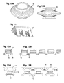
- the embodiment according to Fig. 7A , B is a spring body 10 having a substantially tapered outer shape, wherein the peripheral wall is formed with annular circumferential, horizontal folds or waves.
- a hollow body is particularly easy to compress under vertical load, so that the spring properties are determined in this case essentially by the air pressure in the closed interior.
- Fig. 8 The parallel, substantially horizontal folds of the outer shell extend undulating around the circumference. This improves the tilting rigidity.
- the embodiment aims in the same direction Fig. 9A , B, where the cylindrical shell wall of the spring body 10 shown there is formed with a plurality of radially outwardly facing, regularly arranged and equal sized pyramid tips.
- Fig. 10A , B proved, in which the sheath of the spring body 10 has approximately the shape of a disc and is provided to influence the spring characteristics on both sides around with radially extending depressions, optionally with reduced thickness.
- the spring body 10 according to Fig. 11 designed by uneven formation of its likewise provided with a folding envelope so that its upper part with respect to its lower part with increasing pressurization and under load performs a pivoting movement.
- z. B a peripheral edge lowered or raised.
- Fig. 12A B shows a series of spring bodies 10, which sit with their lower portion astride a serving as a base 12 bar and each extending through a transverse to the bar, in cross-section approximately C-shaped bracket 28, which the underside of the bar and Spring body 10 surrounds and engages in depressions in opposite side walls of the shell, are reliably held on the bar.
- the connection lines 16 extend here between the lower portions of the spring body 10. To simplify the drawing, the flexible pressure distribution element 14 and its connection with the top of the spring body 10 has been omitted.
- FIG. 13A B is another series of pneumatic spring body shown sitting next to each other firmly on a serving as a base 12 bar, but in this case are connected in the upper regions by connecting lines 16.
- the spring bodies 10 are fixed at the top and bottom relative to one another and do not necessarily need to be engaged with the flexible pressure distribution element 14. This is just as shown, placed on projections on the top of the spring body 10.
- the lower portion of the spring body 10 is shaped so that it surrounds the marginal edges of the bar 12 and firmly clamps the bar 12 upon pressure of the inner cavity.
- the lower part of the spring body 10 could be formed by a solid clamp, which can clamp the strip 12 by inherent elasticity and is firmly and tightly connected to the bellows of the pressurizable gas pressure on the top.
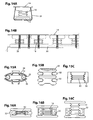
- Fig. 14A B is different from the one after Fig. 13A B, characterized in that the lower portions of the series of spring bodies 10 form a continuous tube 30 which engages over its entire length serving as a base 12 bar at its longitudinal edges and clamps.
- the inner cavity of the tube 30 is in communication with the immediately molded accordion-like sheaths of the spring body 10.
- Their connection to the flexible pressure distribution element 14 may, for. B. as in the execution Fig. 1 be designed.
- FIG. 10 Another design feature for a variety of juxtaposed spring bodies 10 may be that preferably tabs are integrally formed in the head or foot area, the z. B. holes and matching hooks for direct connection of adjacent spring body 10 or by fastening means z. B. are to be connected in the manner of screws or rivets.
- the tilting of the spring body can alternatively or additionally be prevented by the introduction of foam plastic in the interstices, in addition, a damping of the suspension can be achieved.
- the inner cavity except air or another gas may contain an open-cell foam body made of elastic material. This supports the mechanical spring action of the shell and delays the compression of the escape of the air contained in the pores, so has a similar effect as a throttle valve.
- the flexible envelope wall can also be combined on the outside with at least one elastic support body 32 which is compressible under load.
- He can z. B. have the shape of a round in cross-section, oval or rectangular ring, which sits in an outer annular groove of the shell wall of the spring body 10. In this way, one obtains a spring element 10, in which the function of the flexibility concentrated on the shell wall and the function of the mechanical spring action on the or the support body 32.
- Fig. 15A shows such a spring body 10 with support body 32.
- the flexible sheath connects a rigid upper part 34 and a rigid lower part 36. Both are formed on their outside with recesses for positive connection with the base 12 and with the flexible pressure distribution element 14.
- the upper and lower parts 34, 36 may consist of an elastic material and be provided with radial slots in the radially outer regions. Under load, the radial fingers formed thereby can yield axially and spring back. It is understood that such a shell-shaped lower part 36 and possibly also a corresponding upper part 34 also in a spring body 10 according to Fig. 7A , B can be used. The same applies to the execution after Fig. 15B with two annular support bodies 32.
- an elastic support body 32 surrounds the enveloping wall of a spring body 10 provided with horizontal folds.
- the latter can z. B. may be foamed in the existing elastic foam support body 32.
- the support body 32 is compressed as well as the flexible shell wall, which limits the inner cavity of the spring body 10.
- Fig. 16A , B, C shown surrounds a tubular, provided with cavities, made of elastic foam support body 32 the accordion-like folded spring body 10 without intervening between the folds of the shell wall.
- the upper and lower parts of the spring body 10 each have a larger diameter than the middle, folded part.
- the cylindrical support body 32 is located axially between the upper and lower part.
- the folded center region expands and the top raises accordingly Fig. 16C from the support body 32.
- With increasingly stronger load of the spring body 10 then comes the upper part according to Fig. 16B on the support body 32 to the plant, and then this is also compressed, as in Fig. 16A shown.
- FIG. 17 an embodiment in which a group of pneumatic spring bodies 10 is foamed into a mattress 37.
- the mattress can also assume the function of the pressure distribution element, so that under favorable conditions, only a thin mattress or a thin cushion needs to be placed or glued onto the mattress 37 containing the pneumatic spring body 10. If necessary, but also a pressure distribution element 14 can be inserted.
- the execution after Fig. 18 only differs from the after Fig. 17 in that the group of pneumatic spring bodies 10 are inserted into corresponding recesses, which also take into account the connecting lines 16, in the mattress 37.
- the foam surrounding the spring body 10 of the mattress 37 dampens any vibrations.
- the pressure distribution element 14 may be a highly flexible plate, but then not usually well suited for positive connection with the spring body. In addition, it must also have as many air vents 41 with regard to ventilation. It is therefore recommended As a rule, the pressure distribution element 14 of a plurality of small, in each case stable and provided with sufficient air passages 41 parts mosaic-like, wherein the in FIGS. 19 and 20 38, plate-shaped parts are connected by articulated and / or flexible intermediate parts 40.
- the intermediate part may consist of a two plate-shaped parts 38 connecting hinge pin. More mobility provide intermediate parts 40 with two ball joint-like recesses into which spherical projections on the plate-shaped parts 38 are latched.
- kinematic reversal and intermediate parts 40 can engage with spherical ends in spherical shell-shaped recesses in the plates 38.
- Fig. 20 shows a preferred embodiment in which the rectangular plate-shaped parts 38 in rows and columns next to each other and then four or at the edges of two adjacent plate-shaped parts 38 at the corner where they meet, are connected by a flexible intermediate part 40, the z , B. engages with pin-shaped projections in holes 43 in the adjacent corner regions of the plate-shaped parts 38.
- the intermediate parts 40 may be provided with air passages and mounted on the top or bottom of the plate-shaped parts 38.
- Fig. 20 shows different versions.
- the embodiment according to Fig. 21 shows a spring frame, similar to the embodiments according to Fig. 13 and 14 is constructed. Since the spring body 10 are connected to each other in the upper region by connecting lines 16, the lower, tubular portion 30 may be separated from the inner cavity of the spring body 10 and its application of compressed air only serve to firmly clamp the base bar 12.
- a special feature of the embodiment according to Fig. 21 is that in several places a pneumatic height adjustment 42 is available for the base, with a Pressure beaufschlagbares lifting element 44 and the stroke limiting stop 20 has.
- the lifting element 44 may have a similar structure as the spring body 10th
- Fig. 22 shows one opposite Fig. 21 modified, pneumatic device for adjusting the height of the base 12 on a larger scale.
- the base 12 rests at a plurality of locations on each of a pneumatic lifting element 46 and is raised when it is pressurized.
- An upper lifting element 48 arranged above the lower lifting element 46 serves to clamp the base 12.
- the lower and the upper lifting elements 46, 48 may be accommodated in a common holder 47. They could also be used as a pneumatic spring body 10 of a spring frame, especially at high loads, because their shell is not simply a bellows, but consists of superimposed, tight and tightly interconnected, discus or pillow-shaped shells whose interiors on the outside sealed communication openings 49 communicate in the adjacent walls. These prevent buckling of the enveloping wall over its entire height, even if the superimposed hulls are of different sizes and / or have different cross sections. It therefore requires no outer rings or other reinforcements to prevent bulging.
- pneumatic lifting elements also serve to put the base 12 in controlled vibration.
- a lower lifting element 50 and an upper lifting element 52 act by alternately pressurized vibrating on a pivotally connected to the holder and the base drive member 53, the up and out pivotal movement is transmitted via an articulated coupling to the base 12.
- the shape of the Lifting elements 50, 52 is suitably chosen so that its movable end moves arcuately.
- both the spring body 10 shown and described only as an example as well as the base 12 and the pressure distribution elements 14 can be further modified many times, but the functions highlighted here remain preserved. The same applies to the control of the internal pressure of the spring body 10 and lifting elements 44, 46, 48, 50, 52. So these z. B. in addition to a vacuum or vacuum line to be connected to accelerate a lowering process.
Landscapes
- Health & Medical Sciences (AREA)
- Nursing (AREA)
- Life Sciences & Earth Sciences (AREA)
- Animal Behavior & Ethology (AREA)
- General Health & Medical Sciences (AREA)
- Public Health (AREA)
- Veterinary Medicine (AREA)
- Mattresses And Other Support Structures For Chairs And Beds (AREA)
- Invalid Beds And Related Equipment (AREA)
Applications Claiming Priority (1)
| Application Number | Priority Date | Filing Date | Title |
|---|---|---|---|
| DE200810058552 DE102008058552A1 (de) | 2008-11-21 | 2008-11-21 | Federrahmen und Federkörper zur Abstützung z. B. einer Matratze |
Publications (2)
| Publication Number | Publication Date |
|---|---|
| EP2189142A2 true EP2189142A2 (fr) | 2010-05-26 |
| EP2189142A3 EP2189142A3 (fr) | 2012-03-07 |
Family
ID=41651347
Family Applications (1)
| Application Number | Title | Priority Date | Filing Date |
|---|---|---|---|
| EP09014090A Withdrawn EP2189142A3 (fr) | 2008-11-21 | 2009-11-11 | Cadre de ressort et corps de ressort destinés au soutien d'un matelas, par exemple |
Country Status (2)
| Country | Link |
|---|---|
| EP (1) | EP2189142A3 (fr) |
| DE (1) | DE102008058552A1 (fr) |
Cited By (3)
| Publication number | Priority date | Publication date | Assignee | Title |
|---|---|---|---|---|
| AT509583B1 (de) * | 2010-10-25 | 2011-10-15 | Peter Dipl Ing Larsson | Betteinsatz |
| CN109223377A (zh) * | 2018-10-12 | 2019-01-18 | 合肥工业大学 | 一种可调节角度的护理床垫 |
| CN118021097A (zh) * | 2024-03-12 | 2024-05-14 | 深圳雅兰家具有限公司 | 一种弹簧床垫 |
Citations (1)
| Publication number | Priority date | Publication date | Assignee | Title |
|---|---|---|---|---|
| EP1126837A1 (fr) | 1998-10-08 | 2001-08-29 | Enerkom (Pty) Limited | Acide fulvique et utilisation de celui-ci pour le traitement de divers etats pathologiques |
Family Cites Families (11)
| Publication number | Priority date | Publication date | Assignee | Title |
|---|---|---|---|---|
| US2804118A (en) * | 1954-09-13 | 1957-08-27 | Irvin L Bayerkohler | Pneumatic bellows type jacks |
| US3299447A (en) * | 1965-02-09 | 1967-01-24 | Artnell Company | Suspension system for mattresses and the like |
| DE3249598A1 (de) * | 1982-10-27 | 1984-09-20 | Hülsta Werke Hüls KG, 4424 Stadtlohn | Liege |
| US4782542A (en) * | 1985-11-04 | 1988-11-08 | Michiko Tsuchiya | Pneumatic mat with safety apparatus |
| US6047424A (en) * | 1995-08-04 | 2000-04-11 | Hill-Rom, Inc. | Bed having modular therapy devices |
| US6086041A (en) * | 1997-04-07 | 2000-07-11 | Mccord Winn Textron Inc. | Multi-valve module having a ceramic piezoelectric actuator |
| CH691249A5 (fr) * | 2000-05-26 | 2001-06-15 | Marcantonio Del Drago | Dispositif d'appui, notamment matelas, sommier ou pour siège. |
| DE10148569A1 (de) * | 2001-10-01 | 2003-05-08 | Thomas Hilfen Hilbeg Gmbh & Co | Unterfederung für Matratzen oder dergleichen und Verwendung einer solchen Unterfederung |
| CN101090654B (zh) * | 2004-02-13 | 2012-03-14 | 约翰·W.·威尔金森 | 离散单元人体支撑以及用其提供动态按摩的方法 |
| WO2006023479A2 (fr) * | 2004-08-16 | 2006-03-02 | Hill-Rom Services, Inc. | Surface porteuse cellulaire dynamique destinee a des personnes |
| US7657956B2 (en) * | 2006-08-04 | 2010-02-09 | Hill-Rom Services, Inc. | Patient support |
-
2008
- 2008-11-21 DE DE200810058552 patent/DE102008058552A1/de not_active Withdrawn
-
2009
- 2009-11-11 EP EP09014090A patent/EP2189142A3/fr not_active Withdrawn
Patent Citations (1)
| Publication number | Priority date | Publication date | Assignee | Title |
|---|---|---|---|---|
| EP1126837A1 (fr) | 1998-10-08 | 2001-08-29 | Enerkom (Pty) Limited | Acide fulvique et utilisation de celui-ci pour le traitement de divers etats pathologiques |
Cited By (4)
| Publication number | Priority date | Publication date | Assignee | Title |
|---|---|---|---|---|
| AT509583B1 (de) * | 2010-10-25 | 2011-10-15 | Peter Dipl Ing Larsson | Betteinsatz |
| AT509583A4 (de) * | 2010-10-25 | 2011-10-15 | Peter Dipl Ing Larsson | Betteinsatz |
| CN109223377A (zh) * | 2018-10-12 | 2019-01-18 | 合肥工业大学 | 一种可调节角度的护理床垫 |
| CN118021097A (zh) * | 2024-03-12 | 2024-05-14 | 深圳雅兰家具有限公司 | 一种弹簧床垫 |
Also Published As
| Publication number | Publication date |
|---|---|
| EP2189142A3 (fr) | 2012-03-07 |
| DE102008058552A1 (de) | 2010-05-27 |
Similar Documents
| Publication | Publication Date | Title |
|---|---|---|
| EP2029080B1 (fr) | Coussin pour supporter des patients et éviter les escarres de décubitus | |
| EP2403383B1 (fr) | Meuble de repos, notamment meuble pour dormir ou s'allonger | |
| DE202005002906U1 (de) | Polsterfedereinrichtung | |
| EP1904338A1 (fr) | Structures de coussin pneumatiques | |
| DE112016001684T5 (de) | Matratze | |
| EP2225973B1 (fr) | Ressort de matelas | |
| DE60123571T2 (de) | Befestigung für gekoppelte Wellenfedern von Sitz- oder Liegemöbeln | |
| DE3602173C2 (fr) | ||
| WO2011061317A1 (fr) | Élément de soutien déformable, et système de couchage | |
| DE102008058552A1 (de) | Federrahmen und Federkörper zur Abstützung z. B. einer Matratze | |
| EP2229078A1 (fr) | Structure support pour matelas | |
| DE102012202062B4 (de) | Lokalspule für die Magnetresonanzbildgebung | |
| DE10306039B4 (de) | Wassermatratze, insbesondere für ein Wasserbett | |
| EP1371308B1 (fr) | Elément de ressort | |
| WO2020127608A1 (fr) | Dispositif d'aide au positionnement destiné à des examens médicaux | |
| EP1753322B1 (fr) | Coussins pneumatiques pour s'asseoir, s'adosser et s'allonger | |
| DE102006037080B4 (de) | Polsterschicht | |
| DE19715375A1 (de) | Matratze | |
| DE102012217738B4 (de) | Bett | |
| EP0646341A1 (fr) | Grille de support pour meuble d'assise ou de couchage, et éléments de support | |
| EP4176772B1 (fr) | Système de couchage | |
| EP4537709A1 (fr) | Élément ressort, ensemble ressort et rembourrage | |
| EP3972457A1 (fr) | Arrangement pour meuble pour une pièce de mobilier | |
| DE202012007543U1 (de) | Dynamische Sitzvorrichtung | |
| EP3749143B1 (fr) | Siège |
Legal Events
| Date | Code | Title | Description |
|---|---|---|---|
| PUAI | Public reference made under article 153(3) epc to a published international application that has entered the european phase |
Free format text: ORIGINAL CODE: 0009012 |
|
| AK | Designated contracting states |
Kind code of ref document: A2 Designated state(s): AT BE BG CH CY CZ DE DK EE ES FI FR GB GR HR HU IE IS IT LI LT LU LV MC MK MT NL NO PL PT RO SE SI SK SM TR |
|
| AX | Request for extension of the european patent |
Extension state: AL BA RS |
|
| PUAL | Search report despatched |
Free format text: ORIGINAL CODE: 0009013 |
|
| AK | Designated contracting states |
Kind code of ref document: A3 Designated state(s): AT BE BG CH CY CZ DE DK EE ES FI FR GB GR HR HU IE IS IT LI LT LU LV MC MK MT NL NO PL PT RO SE SI SK SM TR |
|
| AX | Request for extension of the european patent |
Extension state: AL BA RS |
|
| RIC1 | Information provided on ipc code assigned before grant |
Ipc: A61G 7/057 20060101AFI20120130BHEP |
|
| STAA | Information on the status of an ep patent application or granted ep patent |
Free format text: STATUS: THE APPLICATION IS DEEMED TO BE WITHDRAWN |
|
| 18D | Application deemed to be withdrawn |
Effective date: 20120908 |