EP2189206B1 - Filterelement mit Haltebändern aus Hochtemperaturpolymer und Herstellungsverfahren - Google Patents
Filterelement mit Haltebändern aus Hochtemperaturpolymer und Herstellungsverfahren Download PDFInfo
- Publication number
- EP2189206B1 EP2189206B1 EP09176386.2A EP09176386A EP2189206B1 EP 2189206 B1 EP2189206 B1 EP 2189206B1 EP 09176386 A EP09176386 A EP 09176386A EP 2189206 B1 EP2189206 B1 EP 2189206B1
- Authority
- EP
- European Patent Office
- Prior art keywords
- filter element
- filtration media
- thermoplastic polyimide
- amorphous thermoplastic
- retention strap
- Prior art date
- Legal status (The legal status is an assumption and is not a legal conclusion. Google has not performed a legal analysis and makes no representation as to the accuracy of the status listed.)
- Active
Links
Images

Classifications
-
- B—PERFORMING OPERATIONS; TRANSPORTING
- B01—PHYSICAL OR CHEMICAL PROCESSES OR APPARATUS IN GENERAL
- B01D—SEPARATION
- B01D46/00—Filters or filtering processes specially modified for separating dispersed particles from gases or vapours
- B01D46/52—Particle separators, e.g. dust precipitators, using filters embodying folded corrugated or wound sheet material
- B01D46/521—Particle separators, e.g. dust precipitators, using filters embodying folded corrugated or wound sheet material using folded, pleated material
- B01D46/523—Particle separators, e.g. dust precipitators, using filters embodying folded corrugated or wound sheet material using folded, pleated material with means for maintaining spacing between the pleats or folds
-
- B—PERFORMING OPERATIONS; TRANSPORTING
- B01—PHYSICAL OR CHEMICAL PROCESSES OR APPARATUS IN GENERAL
- B01D—SEPARATION
- B01D46/00—Filters or filtering processes specially modified for separating dispersed particles from gases or vapours
- B01D46/0001—Making filtering elements
-
- B—PERFORMING OPERATIONS; TRANSPORTING
- B01—PHYSICAL OR CHEMICAL PROCESSES OR APPARATUS IN GENERAL
- B01D—SEPARATION
- B01D46/00—Filters or filtering processes specially modified for separating dispersed particles from gases or vapours
- B01D46/24—Particle separators, e.g. dust precipitators, using rigid hollow filter bodies
- B01D46/2403—Particle separators, e.g. dust precipitators, using rigid hollow filter bodies characterised by the physical shape or structure of the filtering element
- B01D46/2411—Filter cartridges
- B01D46/2414—End caps including additional functions or special forms
-
- B—PERFORMING OPERATIONS; TRANSPORTING
- B01—PHYSICAL OR CHEMICAL PROCESSES OR APPARATUS IN GENERAL
- B01D—SEPARATION
- B01D2265/00—Casings, housings or mounting for filters specially adapted for separating dispersed particles from gases or vapours
- B01D2265/06—Details of supporting structures for filtering material, e.g. cores
Definitions
- the field of the invention relates generally to high temperature filter elements, and more particularly to high temperature filter elements that include high temperature polymer retaining straps.
- Some known filter elements have pleated filtration media for filtering particulates from a particulate laden fluid stream moving in one direction through the filter element.
- Some known particulate laden fluid streams include hot gas streams associated with coal-fired boilers, cement kilns, and asphalt plants. Such hot gas streams may have extended periods of time in which the gas stream temperatures range from approximately 135°C to 260°C (approximately 275°F to 500°F).
- filter elements are often subjected to cleaning fluid pulses moving for short periods of time through the filtration media in a direction opposite to the direction that the particulate laden fluid stream moves. Such filter elements are referred to as "pulse pleat" filter elements.
- some filter elements In order to prevent the filtration media from excessive movement during exposure to the cleaning fluid pulses, some filter elements have retention straps that encircle portions of the pulse pleat filter element.
- Some known retention straps for pulse pleat filter elements are difficult to install onto a filter element and may not remain in the relative axial location that they are initially placed. For example, some known retention straps must be manually wrapped about the filtration media of the filter element. Such retention straps are typically tightened manually and the ends of the retention straps are overlapped. The ends of the retention strap are then adhered or fastened together while a desired tension is manually maintained on the retention strap.
- Maintaining the retention straps in a pre-determined relative axial location along the filter element facilitates protecting the filtration media from excessive movement during exposure to the cleaning fluid pulses. This is typically accomplished by the use of known adhesives. However, some of the adhesives used on the retention straps may have shortened life expectancies, particularly at elevated temperatures of about 190°C to 260°C (about 375°F to 500°F) that are used in some hot gas streams industrial applications
- a filter element for removing particles from a particulate laden fluid stream.
- the filter element includes a filtration media formed into a tubular configuration and that a plurality of circumferentially spaced apart pleats.
- the filter element also includes at least one melt-extruded retention strap extending circumferentially around the filtration media to limit radial movement of the filtration media at operating temperatures up to about 260°C.
- Each melt-extruded retention strap is formed from a melt extrudable amorphous thermoplastic polyimide.
- a method of fabricating a filter element for removing particles from a particulate laden fluid stream includes providing a filtration media formed into a tubular configuration and including a plurality of circumferentially spaced apart pleats. The method also includes extruding an amorphous thermoplastic polyimide circumferentially around a portion of the filtration media to form a retention strap that extends circumferentially around the filtration media to limit radial movement of the filtration media at operating temperatures up to about 260°C.
- US 2008/0072553 discloses a filter cartridge having at least one retention device fabricated from melt extrudable polymer material configured to facilitate extending a life expectancy of the filter cartridge when operationally exposed to operating temperature ranges from 135°C to 204°C (275°F to 400°F).
- a filter element that includes high temperature polymer retention straps and a method of manufacturing the filter element is described below in detail.
- the filter element is suitable for use in hot gas industrial filtration applications up to about 260°C (about 500°F).
- the retention straps are formed from extruded amorphous thermoplastic polyimide polymers or from blends of amorphous thermoplastic polyimide polymers with polyetherimide polymers or polyetheretherketone polymers.
- the retention straps provide for a rigid stable condition of the pleated media under mechanical forces found in pulse-jet filter baghouse environments.
- the extruded polymer retention straps keep the individual pleats of the filter media separate and stable.
- the stability of the pleated media from the melt extruded retaining straps increases the filter media life and performance by reducing flex and stress.
- FIG. 1 is a schematic perspective view of an exemplary filter element 20
- Figure 2 is a schematic side view of filter element 20
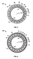
- Figure 3 is a cross-sectional schematic view of filter element 20.
- Filter element 20 may be used to remove particulates from a particulate laden fluid stream that flows in one direction through filter element 20.
- filter element 20 is particularly suitable for use in air pollution control applications that includes, but is not limited to, a bag house substantially removing particulate matter from a flue gas stream associated with a coal-fired furnace.
- filter element 20 is operably attached to a tube sheet 22 positioned within the plenum of the baghouse.
- filter element 20 may be used in any application that requires particulate removal from a fluid stream.
- filter element 20 is a "pulse pleat" type of filter element that is periodically subjected to pulsed cleaning fluid flowing in an opposite direction to the direction that the particulate-laden fluid stream flows.
- pulsed cleaning fluid is compressed, high-pressure, substantially particulate-free air.
- the pulsed cleaning fluid is any fluid that facilitates operation of filter element 20 as described herein.
- Filter element 20 may be subjected to over 300,000 cleaning pulses over its service life of approximately 3 years.
- Filter element 20 includes filtration media 24 that is formed into a tubular configuration that is generally cylindrical, with a longitudinal central axis A.
- Filtration media 24 includes a plurality of pleats 26 which are circumferentially spaced about a periphery 25 of filter element 20.
- Each pleat 26 includes a tip 42 formed at its radially outermost location and a pair of sides 44 extending radially inward from each of tips 42.
- a mounting structure 62 is located at a first axial end portion of filter element 20.
- Mounting structure 62 facilitates mounting and sealing filter element 20 at an opening 64 that is formed in tube sheet 22. Opening 64 facilitates flow of particulate-laden fluid and pulse fluid streams through filter element 20.
- An end cap 66 is located at an axially opposite second axial end portion of filter element 20.
- mounting structure 62 and end cap 66 are made of metal materials that include, but are not limited to, a galvanized steel material.
- structure 62 and end cap 66 are fabricated of any material that facilitates operation of filter element 20 as described herein.
- Filtration media 24 is positioned and maintained in the generally tubular configuration by mounting structure 62 and end cap 66.
- a permeable support 68 is located radially inward of filtration media 24 to prevent inward collapse of filtration media 24 during exposure to the particulate-laden fluid stream that is to be filtered.
- Pleats 26 in filtration media 24 are not necessarily stiff and strong, thus, without a means of restraint, pleats 26 are prone to radially outward movement during a flow of a cleaning fluid pulse through media 24. Excessive radial outward movement of filtration media 24 may reduce a filtration effectiveness of filter element 20. Adjacent pleats 26 may also collapse and temporarily engage one another during a cleaning pulse or during a typical filtration cycle. When adjacent pleats 26 engage one another, there is a chance that the cleaning pulse or filtration operation will not be completely effective because gas flow through that portion of filtration media 24 may be temporarily blocked.
- Filter element 20 includes a plurality of retention straps 82 to restrain filtration media 24 about periphery 25 to facilitate reducing excessive radial movement of filtration media 24 or collapse of pleats 26.
- Retention straps 82 extend around periphery 25 of filter element, and are positioned equidistant along the length of filter element 20. Retention straps 82 limit radial movement of filtration media 24 in the radially outward direction when subjected to the periodic cleaning fluid stream, and thus, limit the possibility of pleat blow-out or catastrophic deformation.
- Retention straps 82 also establish a pre-determined spacing apart and maintaining adjacent pleats 26 at the pre-determined spacing around periphery 25 of filter element 20.
- each retention strap 82 is fabricated from a melt-extrudable polymer material capable of withstanding relatively high-temperature operation, in one embodiment, of up to about 260°C (about 500°F), and in another embodiment from about 190°C to about 260°C (about 375°F to about 500°F).
- a melt-extrudable polymer material capable of withstanding relatively high-temperature operation, in one embodiment, of up to about 260°C (about 500°F), and in another embodiment from about 190°C to about 260°C (about 375°F to about 500°F).
- Such materials have sufficient strength, fatigue resistance, chemical resistance and temperature resistance to limit excessive radial movement of filtration media 24 during a cleaning pulse and maintaining tips 42 of pleats 26 at a pre-determined spacing.
- melt-extrudable polymer material facilitates extending a pre-determined service life of retention strap 82 within environments that have elevated operating temperatures up to about 260°C (about 500°F), for example, from about 190°C to about 260°C (about 375°F to about 500°F).
- retention strap 82 facilitates extending a pre-determined service life within severe operating environments that further include, but are not limited to, routine exposure to moisture and aggressive chemicals.
- retention strap 82 is fabricated from melt-extrudable amorphous thermoplastic polyimide polymers, comprising blends or copolymers, of melt-extrudable amorphous thermoplastic polyimide polymers and other high temperature polymers, selected from the group consisting of polyetherimides and polyetherertherketones (PEEK).
- melt-extrudable amorphous thermoplastic polyimide polymers comprising blends or copolymers, of melt-extrudable amorphous thermoplastic polyimide polymers and other high temperature polymers, selected from the group consisting of polyetherimides and polyetherertherketones (PEEK).
- a blend of amorphous thermoplastic polyimide and polyetherimide or PEEK includes about 40 percent to less than about 100 percent, by weight, of the amorphous thermoplastic polyimide, in another embodiment, the blend includes about 60 percent to less than about 100 percent, by weight, of the amorphous thermoplastic polyimide, and in another embodiment, the blend includes about 80 percent to less than about 100 percent, by weight, of the amorphous thermoplastic polyimide.
- Melt-extrudable amorphous thermoplastic polyimide polymers are commercially available from SABIC Innovative Plastics IP BV under the trademark EXTEM®.
- Melt-extrudable polyetherimide polymers are commercially available from SABIC Innovative Plastics IP BV under the trademark ULTEM®.
- PEEK polymers are commercially available from Victrex plc.
- One particularly suitable copolymer of amorphous thermoplastic polyimide and melt-extrudable polyetherimide is EXTEM® EXUM VH0173 copolymer commercially available from SABIC Innovative Plastics IP BV.
- Table 1 lists the physical properties of EXTEM® EXUM VH0173 copolymer. TABLE 1 PROPERTY UNIT VH0173 Tensile Modulus MPa 3430 Tensile Strength @ Yield MPa 96.3 Elongation @ Break % 42.7 Flexural Modulus MPa 2840 Flexural Stress @ Yield MPa 147 Heat Deflection Temp. °C 243 Notched Izod Ft-lb/in 1.94 Rev-notched Impact Strength Ft-lb/in 32.0 Rev-notched % Ductility % 80
- retention strap 82 can withstand over 300,000 cleaning pulses and continue to function while continuously immersed in an environment that has a temperature up to about 260°C (about 500°F) with a service life of approximately three years without losing its strength and without moving axially along filter element 20 from the position it was initially placed.
- Retention strap 82 extends around periphery 25 and engages and is adhered to tips 42 of pleats 26. Also, retention strap 82 can be adhered to sides 44 of pleats 26. Such engagement minimizes radially outward movement of tips 42 of pleats 26 to facilitate maintaining pleats 26 at their pre-determined spacing without collapsing against one another during exposure to the pressure and flow of the cleaning fluid stream. Such adherence facilitates retention strap 82 remaining in the relative axial location it was originally placed throughout its service life.
- retention strap 82 is applied to filter element 20 during an extrusion operation.
- Retention strap 82 is adhered to filtration media 24 during the extrusion operation so it does not move along periphery 25 of filter element 20 in a direction parallel to axis A.
- a plurality of portions 84 of retention strap 82 are formed which extend at least partially into a region between each of adjacent pleats 26. Forming portions 84 facilitates forming some structure between pleats 26 thereby mitigating a tendency for adjacent pleats 26 from engaging each other and collapsing.
- portions 84 permit retention strap 82 to engage and adhere to tips 42 and/or sides 44 of pleats 26 as described above so that retention strap 82 remains in the pre-determined axial position.
- the polymer material of retention strap 82 is cooled until hardened so that retention strap 82 has a hardness and strength sufficient to withstand the operating environment it will be exposed to during its service life.
- the mitigation of longitudinal movement along periphery 25 of retention strap 82 facilitates the elimination of mechanical wear and abrasion of filtration media 24. Such abrasion may typically be caused by excessive and deleterious longitudinal and radial movement between strap 82 and media 24 during standard flow operations and pulsed operations as described herein.
- FIG. 4 is a cross-sectional schematic view of an alternative filter element 90.
- Filter element 90 is similar to filter element 20 with the exception that filter element 90 includes an alternative retention strap 92 according to another embodiment of the invention.
- Retention strap 92 includes a reinforcement structure 94 that is fabricated with any suitable material including, for example, a woven glass fiber mat, and other suitable textiles.
- Reinforcement structure 94 is introduced during the extrusion operation. For example, in the exemplary embodiment, reinforcement structure 94 is introduced approximately immediately subsequent to formation of a single extrusion pass by pressing structure 94 into the polymer extrudate. Alternatively, structure 94 is introduced between any two separate extrusion passes.
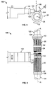
- FIG 5 is a schematic side view of an exemplary polymer application apparatus 100 that can be used to fabricate filter elements 20 and 90 (shown in Figures 1-4 ).
- Figure 6 is a schematic overhead view of polymer application apparatus 100.
- Polymer application apparatus 100 includes an extruder 102, a pivotable application roller 104 positioned in opposition to extruder 102, a cutoff mechanism 106 positioned between extruder 102 and roller 104, and an application barrel 120 coupled in flow communication with a source of hot, melted high-temperature melt-extrudable polymer material.
- apparatus 100 also includes a reinforcement applicator for applying reinforcing structure 94 (shown in Figure 4 ).
- Polymer application apparatus 100 also includes a support mechanism 122 that holds and rotates filter element 20 during application of an extruded retention strap 82.
- Support mechanism 122 includes a mounting structure holder 124 and an end cap holder 126.
- Mounting structure holder 124 is sized to fit within and supports mounting structure 62 of filter element 20 with a friction fit.
- End cap holder 126 is sized to support end cap 66 of filter element 20 via a friction fit.
- Support mechanism 122 positions filter element 20 so longitudinal central axis A of filter element 20 extends in a direction normal to a barrel 120 of extruder 102.
- Either or both of the holders 124 or 126 are rotatably coupled with a drive mechanism to rotate supported filter element 20 under barrel 120 of extruder 102, in a clockwise direction as illustrated by the arrow R illustrated in Figure 5 .
- a method of fabricating filter element 20 with retention strap 82 includes providing filtration media 24 formed into a plurality of pleats 26 having a substantially tubular configuration with a pre-determined circumferential spacing between each of the plurality of pleats 26. The method also includes attaching at least one retention strap 82 to filtration media 24.
- Filter element 20 is held in proximity to extruder 102 by a support mechanism 122.
- the filter element 20 is rotated under barrel 120 of extruder 102 while a band of amorphous thermoplastic polyimide polymer extrudate 144 is applied to periphery 25 of filter element 20.
- Application roller 104 is loaded to a pre-determined force so portions 84 of the polymer extrudate 144 is forced in between adjacent pleats 26 of filtration media 24.
- Application roller 104 also forces polymer extrudate 144 to contact tips 42 and sides 44 of pleats 26 to engage and adhere to filtration media 24.
- Polymer extrudate 144 is subsequently cooled to harden to form retention strap 82.
- reinforcement structure 94 is introduced into retention strap 92.
- One method of introducing reinforcement structure 94 into retention strap 92 is to apply a first layer of polymer extrudate 144 to periphery 25. Reinforcement structure 94 is introduced into extrudate 144 by the optional reinforcement applicator. Application roller 104 depresses textile reinforcement structure 94 into the first layer of polymer extrudate 144. Subsequent layers of polymer extrudate 144 are then formed over and around reinforcement structure 94.
- cutoff mechanism 106 When circumferentially opposite ends of polymer extrudate 144 overlap, cutoff mechanism 106 is activated to sever polymer extrudate 144 moving substantially parallel to axis A as illustrated by the double arrows in Figure 5 .
- Application roller 104 then forms a unified one-piece retention strap 82 (or 90) that substantially remains in the pre-determined axial position and facilitates support of pleats 26 and prevention of engagement between adjacent pleats 26.
Landscapes
- Chemical & Material Sciences (AREA)
- Chemical Kinetics & Catalysis (AREA)
- Physics & Mathematics (AREA)
- Geometry (AREA)
- Filtering Materials (AREA)
- Extrusion Moulding Of Plastics Or The Like (AREA)
- Filtering Of Dispersed Particles In Gases (AREA)
- Macromolecular Compounds Obtained By Forming Nitrogen-Containing Linkages In General (AREA)
Claims (12)
- Filterelement (20), aufweisend:ein Filtrationsmedium (24), das zu einer rohrartigen Anordnung geformt ist und mehrere in Umfangsrichtung in Abstand angeordnete Falten (26) aufweist; undeine Befestigungsstruktur (62) an einem ersten axialen Ende des Filterelementes; undeine Endkappe (66) an einem zweiten axialen Ende des Filterelementes, wobei sich das Filtrationsmedium (24) zwischen der Befestigungsstruktur und der Endkappe erstreckt; undwenigstens ein sich in Umfangsrichtung um das Filtrationsmedium erstreckendes schmelzextrudiertes Halteband (82), um eine radiale Bewegung des Filtrationsmediums bei Betriebstemperaturen bis zu ca. 260 °C (500 °F) zu begrenzen, wobei das wenigstens eine schmelzextrudierte Halteband (82) ein schmelzextrudierbares amorphes thermoplastisches Polyimid aufweist,wobei das amorphe thermoplastische Polyimid ein Copolymer von einem oder ein Gemisch von einem amorphen thermoplastischen Polyimidpolymer und einem weiteren aus der aus Polyetherimidpolymeren und Polyetherketonpolymeren bestehenden Gruppe ausgewählten Polymer aufweist.
- Filterelement (20) nach Anspruch 1, wobei das Copolymer oder das Gemisch ca. 40 bis weniger als ca. 100 Gewichtsprozent von dem amorphen thermoplastischen Polyimidpolymer aufweist.
- Filterelement (20) nach Anspruch 1, wobei das Copolymer oder das Gemisch ca. 80 bis weniger als ca. 100 Gewichtsprozent von dem amorphen thermoplastischen Polyimidpolymer aufweist.
- Filterelement (20) nach einem der vorstehenden Ansprüche, wobei wenigstens eine von den mehreren Falten (26) ein Paar im Wesentlichen schräger Seiten (44) aufweist, die wenigstens eine Spitze (42) ausbilden, wobei das Halteband (82) mit wenigstens einer von den Spitzen (42) verbunden ist.
- Filterelement (20) nach Anspruch 4, wobei das wenigstens eine Halteband (82) mit wenigstens einer von den in Wesentlichen schrägen Seiten (44) verbunden ist.
- Filterelement (20) nach einem der Ansprüche 1 bis 5, wobei das wenigstens eine Halteband (82) einen sich zwischen benachbarten Falten (26) erstreckenden Anteil aufweist.
- Filterelement (20) nach einem der vorstehenden Ansprüche, wobei das wenigstens eine Halteband (82) ferner eine Verstärkungsstruktur (94) aufweist.
- Filterelement (20) nach Anspruch 1, wobei sich das wenigstens eine schmelzextrudierte Halteband (82) in Umfangsrichtung um das Filtrationsmedium (24) erstreckt, um eine radiale Bewegung des Filtrationsmediums bei Betriebstemperaturen von ca. 190 °C (375 °F) bis ca. 260 °C (500 °F) zu begrenzen.
- Verfahren zum Herstellen eines Filterelementes (20), wobei das Verfahren die Schritte aufweist:Bereitstellen eines Filtrationsmediums (24), das zu einer rohrartigen Anordnung geformt ist und mehrere in Umfangsrichtung in Abstand angeordnete Falten (26) aufweist; undAnkoppeln einer Befestigungsstruktur (62) an einem ersten axialen Ende des Filterelementes; undAnkoppeln einer Endkappe (66) an einem zweiten axialen Ende des Filterelementes, wobei sich das Filtrationsmedium (24) zwischen der Befestigungsstruktur und der Kappe erstreckt; undExtrudieren eines amorphen thermoplastischen Polyimids in Umfangsrichtung um einen Abschnitt des Filtrationsmediums, um ein Halteband auszubilden, das sich in Umfangsrichtung um das Filtrationsmedium erstreckt, um eine radiale Bewegung des Filtrationsmediums bei Betriebstemperaturen bis zu ca. 260 °C (500 °F) zu begrenzen.wobei das amorphe schmelzextrudierte thermoplastische ein Copolymer von einem oder ein Gemisch von einem amorphen thermoplastischen Polyimidpolymer und einem weiteren aus der aus Polyetherimidpolymeren und Polyetherketonpolymeren bestehenden Gruppe ausgewählten Polymer aufweist.
- Verfahren nach Anspruch 9, wobei wenigstens eine von den mehreren Falten (26) ein Paar im Wesentlichen schräger Seiten (44) aufweist, die wenigstens eine Spitze (42) ausbilden, wobei das Extrudieren eines amorphen thermoplastischen Polyimidpolymers um einen Abschnitt des Filtrationsmediums das Extrudieren eines amorphen thermoplastischen Polyimidpolymers um einen Abschnitt des Filtrationsmediums dergestalt umfasst, dass es das Halteband (82, 92) an wenigsten einer der Spitzen (42) ankoppelt.
- Verfahren nach Anspruch 10, wobei das Extrudieren eines amorphen thermoplastischen Polyimidpolymers um einen Abschnitt des Filtrationsmediums das Extrudieren eines amorphen thermoplastischen Polyimidpolymers um einen Abschnitt des Filtrationsmediums dergestalt umfasst, dass es das Halteband (82, 92) an wenigstem eine von den schrägen Seiten (44) der mehreren Falten (26) ankoppelt.
- Verfahren nach Anspruch 9 oder Anspruch 10, wobei das Extrudieren eines amorphen thermoplastischen Polyimids in Umfangsrichtung um einen Abschnitt des Filtrationsmediums das Extrudieren eines amorphen thermoplastischen Polyimids in Umfangsrichtung um einen Abschnitt des Filtrationsmediums dergestalt umfasst, dass der Haltestreifen (82) einen sich zwischen benachbarten Falten (26) erstreckenden Abschnitt aufweist.
Applications Claiming Priority (1)
| Application Number | Priority Date | Filing Date | Title |
|---|---|---|---|
| US12/275,988 US8021456B2 (en) | 2008-11-21 | 2008-11-21 | Filter element with high temperature polymer retaining straps and method of manufacture |
Publications (3)
| Publication Number | Publication Date |
|---|---|
| EP2189206A2 EP2189206A2 (de) | 2010-05-26 |
| EP2189206A3 EP2189206A3 (de) | 2012-05-09 |
| EP2189206B1 true EP2189206B1 (de) | 2013-09-25 |
Family
ID=41716345
Family Applications (1)
| Application Number | Title | Priority Date | Filing Date |
|---|---|---|---|
| EP09176386.2A Active EP2189206B1 (de) | 2008-11-21 | 2009-11-18 | Filterelement mit Haltebändern aus Hochtemperaturpolymer und Herstellungsverfahren |
Country Status (4)
| Country | Link |
|---|---|
| US (1) | US8021456B2 (de) |
| EP (1) | EP2189206B1 (de) |
| CN (1) | CN101898063B (de) |
| DK (1) | DK2189206T3 (de) |
Families Citing this family (2)
| Publication number | Priority date | Publication date | Assignee | Title |
|---|---|---|---|---|
| US20140360147A1 (en) * | 2013-06-05 | 2014-12-11 | Bha Altair, Llc | Filter element with high temperature polymer retaining straps and method of manufacture |
| US20150151236A1 (en) * | 2013-12-04 | 2015-06-04 | Bha Altair, Llc | Filter media and method of forming thereof |
Family Cites Families (26)
| Publication number | Priority date | Publication date | Assignee | Title |
|---|---|---|---|---|
| US3857688A (en) * | 1971-10-27 | 1974-12-31 | Ppg Industries Inc | Lead filter |
| US4154688A (en) * | 1978-01-27 | 1979-05-15 | Pall Corporation | Collapse-resistant corrugated filter element |
| US4402830A (en) * | 1982-01-13 | 1983-09-06 | Pall Corporation | Corrugated filter element with external spiral tape support |
| US4444575A (en) * | 1982-08-31 | 1984-04-24 | Rockwell International Corporation | Filter system |
| US5552048A (en) * | 1988-06-15 | 1996-09-03 | Pall Corporation | Two pleated filter composite having cushioning layers |
| US5316677A (en) * | 1990-06-25 | 1994-05-31 | Harmsco, Inc. | Pleated filtering sleeve for rotational flow filter systems |
| US5211846A (en) * | 1990-07-30 | 1993-05-18 | Pleatco Electronic & Filter Corp. | Replacement filter cartridge assembly |
| US5350513A (en) * | 1992-07-02 | 1994-09-27 | Calgon Carbon Corporation | Flexible-walled absorber |
| US5543047A (en) * | 1992-11-06 | 1996-08-06 | Pall Corporation | Filter with over-laid pleats in intimate contact |
| US5904846A (en) * | 1996-01-16 | 1999-05-18 | Corning Costar Corporation | Filter cartridge having track etched membranes and methods of making same |
| US5916435A (en) * | 1997-01-27 | 1999-06-29 | Porous Media Corporation | Conical coreless filter assembly and element |
| US6233790B1 (en) * | 1999-06-30 | 2001-05-22 | Bha Group Holdings, Inc. | Outer strap for air filter cartridge |
| US6508934B2 (en) * | 2000-12-15 | 2003-01-21 | Bha Group Holdings, Inc. | Filter cartridge with strap and method |
| US6911144B2 (en) * | 2000-12-15 | 2005-06-28 | Bha Group Holdings, Inc. | Filter cartridge with strap and method |
| US6752847B2 (en) * | 2001-11-30 | 2004-06-22 | Bha Group Holdings, Inc. | High temperature polymer filtration medium |
| US6955701B2 (en) * | 2002-03-28 | 2005-10-18 | Donaldson Company, Inc. | Filter element and use thereof; methods of manufacture |
| US20030192294A1 (en) * | 2002-04-16 | 2003-10-16 | Alan Smithies | Filter medium |
| WO2004039476A1 (en) * | 2002-10-28 | 2004-05-13 | Donaldson Company, Inc. | Air cleaner; replaceable filter cartridges; and, methods |
| US20040163372A1 (en) * | 2003-02-25 | 2004-08-26 | Nguyen Ledu Q. | Environmentally friendly air filter for an internal combustion engine |
| US6858052B2 (en) * | 2003-05-30 | 2005-02-22 | Bha Group, Inc. | Filter cartridge mounting structure |
| EP1666573B1 (de) * | 2003-08-06 | 2019-05-15 | Nissan Motor Company Limited | Reibungsarmer gleitmechanismus und reibungsverringerungsverfahren |
| US8202613B2 (en) * | 2005-05-18 | 2012-06-19 | Sumitomo Chemical Company, Limited | Multilayer pellet and method for producing the same |
| US9102103B2 (en) * | 2006-02-02 | 2015-08-11 | The Boeing Company | Thermoplastic composite parts having integrated metal fittings and method of making the same |
| US20080072553A1 (en) * | 2006-09-25 | 2008-03-27 | Alan Smithies | Method and apparatus for assembling a filter cartridge |
| US7985275B2 (en) * | 2006-10-02 | 2011-07-26 | General Electric Company | Filter media and devices for high temperature filtration and methods |
| US8343250B2 (en) * | 2007-05-02 | 2013-01-01 | E I Du Pont De Nemours And Company | Bag house filters and media |
-
2008
- 2008-11-21 US US12/275,988 patent/US8021456B2/en active Active
-
2009
- 2009-11-18 EP EP09176386.2A patent/EP2189206B1/de active Active
- 2009-11-18 DK DK09176386.2T patent/DK2189206T3/da active
- 2009-11-20 CN CN200910246418.XA patent/CN101898063B/zh active Active
Also Published As
| Publication number | Publication date |
|---|---|
| CN101898063B (zh) | 2013-03-13 |
| EP2189206A3 (de) | 2012-05-09 |
| US20100126130A1 (en) | 2010-05-27 |
| US8021456B2 (en) | 2011-09-20 |
| EP2189206A2 (de) | 2010-05-26 |
| DK2189206T3 (da) | 2013-11-25 |
| CN101898063A (zh) | 2010-12-01 |
Similar Documents
| Publication | Publication Date | Title |
|---|---|---|
| US6911144B2 (en) | Filter cartridge with strap and method | |
| US20080272048A1 (en) | Filter cartridge media retention system | |
| US8506667B2 (en) | Filters and methods for imparting structural support to pleated filter media | |
| US6508934B2 (en) | Filter cartridge with strap and method | |
| EP1908507A1 (de) | Verfahren und Vorrichtung zur Montage einer Filterkartusche | |
| CN102100992A (zh) | Ptfe折褶过滤元件 | |
| EP2189206B1 (de) | Filterelement mit Haltebändern aus Hochtemperaturpolymer und Herstellungsverfahren | |
| US20180290088A1 (en) | Self-supporting industrial air filter | |
| KR20120011792A (ko) | 코어리스 필터 카트리지 | |
| US20140360147A1 (en) | Filter element with high temperature polymer retaining straps and method of manufacture | |
| KR200295354Y1 (ko) | 필터 | |
| WO2000072942A1 (en) | Adjustable filter bag retainer |
Legal Events
| Date | Code | Title | Description |
|---|---|---|---|
| PUAI | Public reference made under article 153(3) epc to a published international application that has entered the european phase |
Free format text: ORIGINAL CODE: 0009012 |
|
| AK | Designated contracting states |
Kind code of ref document: A2 Designated state(s): AT BE BG CH CY CZ DE DK EE ES FI FR GB GR HR HU IE IS IT LI LT LU LV MC MK MT NL NO PL PT RO SE SI SK SM TR |
|
| AX | Request for extension of the european patent |
Extension state: AL BA RS |
|
| PUAL | Search report despatched |
Free format text: ORIGINAL CODE: 0009013 |
|
| AK | Designated contracting states |
Kind code of ref document: A3 Designated state(s): AT BE BG CH CY CZ DE DK EE ES FI FR GB GR HR HU IE IS IT LI LT LU LV MC MK MT NL NO PL PT RO SE SI SK SM TR |
|
| AX | Request for extension of the european patent |
Extension state: AL BA RS |
|
| RIC1 | Information provided on ipc code assigned before grant |
Ipc: B01D 46/24 20060101ALI20120403BHEP Ipc: B01D 46/52 20060101ALI20120403BHEP Ipc: B01D 46/00 20060101AFI20120403BHEP |
|
| 17P | Request for examination filed |
Effective date: 20121109 |
|
| GRAP | Despatch of communication of intention to grant a patent |
Free format text: ORIGINAL CODE: EPIDOSNIGR1 |
|
| INTG | Intention to grant announced |
Effective date: 20130508 |
|
| GRAS | Grant fee paid |
Free format text: ORIGINAL CODE: EPIDOSNIGR3 |
|
| GRAA | (expected) grant |
Free format text: ORIGINAL CODE: 0009210 |
|
| AK | Designated contracting states |
Kind code of ref document: B1 Designated state(s): AT BE BG CH CY CZ DE DK EE ES FI FR GB GR HR HU IE IS IT LI LT LU LV MC MK MT NL NO PL PT RO SE SI SK SM TR |
|
| REG | Reference to a national code |
Ref country code: GB Ref legal event code: FG4D |
|
| REG | Reference to a national code |
Ref country code: CH Ref legal event code: EP |
|
| REG | Reference to a national code |
Ref country code: AT Ref legal event code: REF Ref document number: 633491 Country of ref document: AT Kind code of ref document: T Effective date: 20131015 |
|
| REG | Reference to a national code |
Ref country code: IE Ref legal event code: FG4D |
|
| REG | Reference to a national code |
Ref country code: DE Ref legal event code: R096 Ref document number: 602009019025 Country of ref document: DE Effective date: 20131121 |
|
| REG | Reference to a national code |
Ref country code: DK Ref legal event code: T3 Effective date: 20131119 |
|
| PG25 | Lapsed in a contracting state [announced via postgrant information from national office to epo] |
Ref country code: SE Free format text: LAPSE BECAUSE OF FAILURE TO SUBMIT A TRANSLATION OF THE DESCRIPTION OR TO PAY THE FEE WITHIN THE PRESCRIBED TIME-LIMIT Effective date: 20130925 Ref country code: NO Free format text: LAPSE BECAUSE OF FAILURE TO SUBMIT A TRANSLATION OF THE DESCRIPTION OR TO PAY THE FEE WITHIN THE PRESCRIBED TIME-LIMIT Effective date: 20131225 Ref country code: LT Free format text: LAPSE BECAUSE OF FAILURE TO SUBMIT A TRANSLATION OF THE DESCRIPTION OR TO PAY THE FEE WITHIN THE PRESCRIBED TIME-LIMIT Effective date: 20130925 Ref country code: HR Free format text: LAPSE BECAUSE OF FAILURE TO SUBMIT A TRANSLATION OF THE DESCRIPTION OR TO PAY THE FEE WITHIN THE PRESCRIBED TIME-LIMIT Effective date: 20130925 |
|
| REG | Reference to a national code |
Ref country code: AT Ref legal event code: MK05 Ref document number: 633491 Country of ref document: AT Kind code of ref document: T Effective date: 20130925 |
|
| REG | Reference to a national code |
Ref country code: NL Ref legal event code: VDEP Effective date: 20130925 |
|
| REG | Reference to a national code |
Ref country code: LT Ref legal event code: MG4D |
|
| REG | Reference to a national code |
Ref country code: GB Ref legal event code: 732E Free format text: REGISTERED BETWEEN 20140130 AND 20140205 |
|
| PG25 | Lapsed in a contracting state [announced via postgrant information from national office to epo] |
Ref country code: FI Free format text: LAPSE BECAUSE OF FAILURE TO SUBMIT A TRANSLATION OF THE DESCRIPTION OR TO PAY THE FEE WITHIN THE PRESCRIBED TIME-LIMIT Effective date: 20130925 Ref country code: GR Free format text: LAPSE BECAUSE OF FAILURE TO SUBMIT A TRANSLATION OF THE DESCRIPTION OR TO PAY THE FEE WITHIN THE PRESCRIBED TIME-LIMIT Effective date: 20131226 Ref country code: LV Free format text: LAPSE BECAUSE OF FAILURE TO SUBMIT A TRANSLATION OF THE DESCRIPTION OR TO PAY THE FEE WITHIN THE PRESCRIBED TIME-LIMIT Effective date: 20130925 Ref country code: SI Free format text: LAPSE BECAUSE OF FAILURE TO SUBMIT A TRANSLATION OF THE DESCRIPTION OR TO PAY THE FEE WITHIN THE PRESCRIBED TIME-LIMIT Effective date: 20130925 |
|
| REG | Reference to a national code |
Ref country code: CH Ref legal event code: PUE Owner name: BHA ALTAIR, LLC, US Free format text: FORMER OWNER: BHA GROUP, INC., FR Ref country code: CH Ref legal event code: PFUS Owner name: BHA GROUP, INC., FR Free format text: FORMER OWNER: BHA GROUP HOLDINGS INC., US Ref country code: CH Ref legal event code: NV Representative=s name: E. BLUM AND CO. AG PATENT- UND MARKENANWAELTE , CH |
|
| RAP2 | Party data changed (patent owner data changed or rights of a patent transferred) |
Owner name: BHA GROUP, INC |
|
| PG25 | Lapsed in a contracting state [announced via postgrant information from national office to epo] |
Ref country code: BE Free format text: LAPSE BECAUSE OF FAILURE TO SUBMIT A TRANSLATION OF THE DESCRIPTION OR TO PAY THE FEE WITHIN THE PRESCRIBED TIME-LIMIT Effective date: 20130925 |
|
| PG25 | Lapsed in a contracting state [announced via postgrant information from national office to epo] |
Ref country code: EE Free format text: LAPSE BECAUSE OF FAILURE TO SUBMIT A TRANSLATION OF THE DESCRIPTION OR TO PAY THE FEE WITHIN THE PRESCRIBED TIME-LIMIT Effective date: 20130925 Ref country code: SK Free format text: LAPSE BECAUSE OF FAILURE TO SUBMIT A TRANSLATION OF THE DESCRIPTION OR TO PAY THE FEE WITHIN THE PRESCRIBED TIME-LIMIT Effective date: 20130925 Ref country code: IS Free format text: LAPSE BECAUSE OF FAILURE TO SUBMIT A TRANSLATION OF THE DESCRIPTION OR TO PAY THE FEE WITHIN THE PRESCRIBED TIME-LIMIT Effective date: 20140125 Ref country code: NL Free format text: LAPSE BECAUSE OF FAILURE TO SUBMIT A TRANSLATION OF THE DESCRIPTION OR TO PAY THE FEE WITHIN THE PRESCRIBED TIME-LIMIT Effective date: 20130925 Ref country code: RO Free format text: LAPSE BECAUSE OF FAILURE TO SUBMIT A TRANSLATION OF THE DESCRIPTION OR TO PAY THE FEE WITHIN THE PRESCRIBED TIME-LIMIT Effective date: 20130925 Ref country code: CZ Free format text: LAPSE BECAUSE OF FAILURE TO SUBMIT A TRANSLATION OF THE DESCRIPTION OR TO PAY THE FEE WITHIN THE PRESCRIBED TIME-LIMIT Effective date: 20130925 |
|
| RAP2 | Party data changed (patent owner data changed or rights of a patent transferred) |
Owner name: BHA ALTAIR, LLC |
|
| PG25 | Lapsed in a contracting state [announced via postgrant information from national office to epo] |
Ref country code: PL Free format text: LAPSE BECAUSE OF FAILURE TO SUBMIT A TRANSLATION OF THE DESCRIPTION OR TO PAY THE FEE WITHIN THE PRESCRIBED TIME-LIMIT Effective date: 20130925 Ref country code: ES Free format text: LAPSE BECAUSE OF FAILURE TO SUBMIT A TRANSLATION OF THE DESCRIPTION OR TO PAY THE FEE WITHIN THE PRESCRIBED TIME-LIMIT Effective date: 20130925 Ref country code: AT Free format text: LAPSE BECAUSE OF FAILURE TO SUBMIT A TRANSLATION OF THE DESCRIPTION OR TO PAY THE FEE WITHIN THE PRESCRIBED TIME-LIMIT Effective date: 20130925 Ref country code: CY Free format text: LAPSE BECAUSE OF FAILURE TO SUBMIT A TRANSLATION OF THE DESCRIPTION OR TO PAY THE FEE WITHIN THE PRESCRIBED TIME-LIMIT Effective date: 20130925 |
|
| REG | Reference to a national code |
Ref country code: DE Ref legal event code: R097 Ref document number: 602009019025 Country of ref document: DE |
|
| PG25 | Lapsed in a contracting state [announced via postgrant information from national office to epo] |
Ref country code: PT Free format text: LAPSE BECAUSE OF FAILURE TO SUBMIT A TRANSLATION OF THE DESCRIPTION OR TO PAY THE FEE WITHIN THE PRESCRIBED TIME-LIMIT Effective date: 20140127 |
|
| PG25 | Lapsed in a contracting state [announced via postgrant information from national office to epo] |
Ref country code: MC Free format text: LAPSE BECAUSE OF FAILURE TO SUBMIT A TRANSLATION OF THE DESCRIPTION OR TO PAY THE FEE WITHIN THE PRESCRIBED TIME-LIMIT Effective date: 20130925 |
|
| PLBE | No opposition filed within time limit |
Free format text: ORIGINAL CODE: 0009261 |
|
| STAA | Information on the status of an ep patent application or granted ep patent |
Free format text: STATUS: NO OPPOSITION FILED WITHIN TIME LIMIT |
|
| REG | Reference to a national code |
Ref country code: DE Ref legal event code: R081 Ref document number: 602009019025 Country of ref document: DE Owner name: BHA ALTAIR, LLC (N. D. GES. D. STAATES DELAWAR, US Free format text: FORMER OWNER: BHA GROUP HOLDINGS, INC., KANSAS CITY, MO., US Effective date: 20140709 |
|
| REG | Reference to a national code |
Ref country code: FR Ref legal event code: ST Effective date: 20140731 |
|
| REG | Reference to a national code |
Ref country code: IE Ref legal event code: MM4A |
|
| PG25 | Lapsed in a contracting state [announced via postgrant information from national office to epo] |
Ref country code: IT Free format text: LAPSE BECAUSE OF FAILURE TO SUBMIT A TRANSLATION OF THE DESCRIPTION OR TO PAY THE FEE WITHIN THE PRESCRIBED TIME-LIMIT Effective date: 20130925 |
|
| 26N | No opposition filed |
Effective date: 20140626 |
|
| REG | Reference to a national code |
Ref country code: DE Ref legal event code: R097 Ref document number: 602009019025 Country of ref document: DE Effective date: 20140626 |
|
| PG25 | Lapsed in a contracting state [announced via postgrant information from national office to epo] |
Ref country code: IE Free format text: LAPSE BECAUSE OF NON-PAYMENT OF DUE FEES Effective date: 20131118 |
|
| PG25 | Lapsed in a contracting state [announced via postgrant information from national office to epo] |
Ref country code: FR Free format text: LAPSE BECAUSE OF NON-PAYMENT OF DUE FEES Effective date: 20131202 |
|
| PG25 | Lapsed in a contracting state [announced via postgrant information from national office to epo] |
Ref country code: SM Free format text: LAPSE BECAUSE OF FAILURE TO SUBMIT A TRANSLATION OF THE DESCRIPTION OR TO PAY THE FEE WITHIN THE PRESCRIBED TIME-LIMIT Effective date: 20130925 |
|
| PG25 | Lapsed in a contracting state [announced via postgrant information from national office to epo] |
Ref country code: HU Free format text: LAPSE BECAUSE OF FAILURE TO SUBMIT A TRANSLATION OF THE DESCRIPTION OR TO PAY THE FEE WITHIN THE PRESCRIBED TIME-LIMIT; INVALID AB INITIO Effective date: 20091118 Ref country code: BG Free format text: LAPSE BECAUSE OF FAILURE TO SUBMIT A TRANSLATION OF THE DESCRIPTION OR TO PAY THE FEE WITHIN THE PRESCRIBED TIME-LIMIT Effective date: 20130925 Ref country code: LU Free format text: LAPSE BECAUSE OF NON-PAYMENT OF DUE FEES Effective date: 20131118 Ref country code: MK Free format text: LAPSE BECAUSE OF FAILURE TO SUBMIT A TRANSLATION OF THE DESCRIPTION OR TO PAY THE FEE WITHIN THE PRESCRIBED TIME-LIMIT Effective date: 20130925 |
|
| PG25 | Lapsed in a contracting state [announced via postgrant information from national office to epo] |
Ref country code: MT Free format text: LAPSE BECAUSE OF FAILURE TO SUBMIT A TRANSLATION OF THE DESCRIPTION OR TO PAY THE FEE WITHIN THE PRESCRIBED TIME-LIMIT Effective date: 20130925 |
|
| REG | Reference to a national code |
Ref country code: GB Ref legal event code: 732E Free format text: REGISTERED BETWEEN 20210826 AND 20210901 |
|
| REG | Reference to a national code |
Ref country code: DE Ref legal event code: R081 Ref document number: 602009019025 Country of ref document: DE Owner name: PARKER-HANNIFIN CORP., CLEVELAND, US Free format text: FORMER OWNER: BHA ALTAIR, LLC (N. D. GES. D. STAATES DELAWARE), FRANKLIN, TENN., US |
|
| P01 | Opt-out of the competence of the unified patent court (upc) registered |
Effective date: 20230524 |
|
| REG | Reference to a national code |
Ref country code: CH Ref legal event code: U11 Free format text: ST27 STATUS EVENT CODE: U-0-0-U10-U11 (AS PROVIDED BY THE NATIONAL OFFICE) Effective date: 20251201 |
|
| PGFP | Annual fee paid to national office [announced via postgrant information from national office to epo] |
Ref country code: DE Payment date: 20251128 Year of fee payment: 17 |
|
| PGFP | Annual fee paid to national office [announced via postgrant information from national office to epo] |
Ref country code: GB Payment date: 20251127 Year of fee payment: 17 |
|
| PGFP | Annual fee paid to national office [announced via postgrant information from national office to epo] |
Ref country code: DK Payment date: 20251125 Year of fee payment: 17 |
|
| PGFP | Annual fee paid to national office [announced via postgrant information from national office to epo] |
Ref country code: TR Payment date: 20251104 Year of fee payment: 17 |
|
| PGFP | Annual fee paid to national office [announced via postgrant information from national office to epo] |
Ref country code: CH Payment date: 20251201 Year of fee payment: 17 |