EP2189249B1 - Dispositif de machine-outil et machine-outil - Google Patents
Dispositif de machine-outil et machine-outil Download PDFInfo
- Publication number
- EP2189249B1 EP2189249B1 EP09171301.6A EP09171301A EP2189249B1 EP 2189249 B1 EP2189249 B1 EP 2189249B1 EP 09171301 A EP09171301 A EP 09171301A EP 2189249 B1 EP2189249 B1 EP 2189249B1
- Authority
- EP
- European Patent Office
- Prior art keywords
- control
- impact
- tool
- parameter
- handheld machine
- Prior art date
- Legal status (The legal status is an assumption and is not a legal conclusion. Google has not performed a legal analysis and makes no representation as to the accuracy of the status listed.)
- Not-in-force
Links
Images

Classifications
-
- B—PERFORMING OPERATIONS; TRANSPORTING
- B25—HAND TOOLS; PORTABLE POWER-DRIVEN TOOLS; MANIPULATORS
- B25D—PERCUSSIVE TOOLS
- B25D17/00—Details of, or accessories for, portable power-driven percussive tools
- B25D17/24—Damping the reaction force
-
- B—PERFORMING OPERATIONS; TRANSPORTING
- B25—HAND TOOLS; PORTABLE POWER-DRIVEN TOOLS; MANIPULATORS
- B25D—PERCUSSIVE TOOLS
- B25D2211/00—Details of portable percussive tools with electromotor or other motor drive
- B25D2211/06—Means for driving the impulse member
- B25D2211/068—Crank-actuated impulse-driving mechanisms
-
- B—PERFORMING OPERATIONS; TRANSPORTING
- B25—HAND TOOLS; PORTABLE POWER-DRIVEN TOOLS; MANIPULATORS
- B25D—PERCUSSIVE TOOLS
- B25D2216/00—Details of portable percussive machines with superimposed rotation, the rotational movement of the output shaft of a motor being modified to generate axial impacts on the tool bit
- B25D2216/0084—Mode-changing mechanisms
-
- B—PERFORMING OPERATIONS; TRANSPORTING
- B25—HAND TOOLS; PORTABLE POWER-DRIVEN TOOLS; MANIPULATORS
- B25D—PERCUSSIVE TOOLS
- B25D2250/00—General details of portable percussive tools; Components used in portable percussive tools
- B25D2250/195—Regulation means
-
- B—PERFORMING OPERATIONS; TRANSPORTING
- B25—HAND TOOLS; PORTABLE POWER-DRIVEN TOOLS; MANIPULATORS
- B25D—PERCUSSIVE TOOLS
- B25D2250/00—General details of portable percussive tools; Components used in portable percussive tools
- B25D2250/221—Sensors
Definitions
- the invention relates to a hand-held power tool device according to the preamble of claim 1.
- a hand-held power tool device is known from the GB 2 411 375 A known.
- the invention is based on a handheld power tool device having at least one impact device.
- the impact device has a control device, which is provided to control at least one impact characteristic with respect to the vibration and the impact effect.
- An "impact characteristic” is intended to be understood to mean an effect of an operation, wherein the control device is provided, in particular, for regulating the impact characteristic by means of a frequency change of the impact device and / or a speed change of an engine.
- the motor may be formed by a pneumatic motor or particularly advantageous by an electric motor.
- “provided” is to be understood in particular specially equipped, designed and / or programmed. Due to the inventive design of the power tool device can by means of the scheme the at least one impact characteristic, the impact device are largely optimized regardless of the properties of a workpiece.
- control device on a computing unit, which is at least provided to determine depending on at least one parameter, at least one feedback variable of the impact characteristic.
- a "computing unit” is to be understood in particular as meaning a microcontroller having a processor, a memory unit and an operating program stored in the memory unit and / or calculation routines and / or control routines stored in the memory unit.
- a "parameter” is to be understood as meaning a value and / or a value course which is dependent on internal and / or external influences and measured during operation and which is at least partially descriptive of the at least one impact parameter. Internal influences are in particular a temperature and / or a lubrication of parts of a hand tool.
- a feedback variable is to be understood as meaning calculated information about the impact characteristic, which can be used to control the impact parameter.
- the control can include various parameters in the control and be designed to be particularly flexible.
- control device a control routine, which is intended to control at least the impact characteristic based on at least one operating point.
- a "control routine” is to be understood, in particular, as a routine which carries out the calculations necessary for control during operation and outputs results.
- the control routine runs on a computer.
- An "operating point” is to be understood as an operating state in which at least one impact parameter in an operation is regulated to a predetermined value curve.
- the operating point preferably has a desired course and / or a desired value of the impact characteristic.
- control device on at least one measuring device, whereby the control device and the measuring device can be advantageously coordinated.
- the measuring device is intended to detect at least one parameter as a function of which the feedback variable of the impact characteristic is determined.
- the measuring device has at least one acceleration sensor, which is provided to detect at least one acceleration parameter of a handheld power tool.
- An “acceleration parameter” should be understood to mean a measured acceleration profile in at least one axis which is parallel to a main working direction.
- the acceleration parameter forms a particularly accurate parameter for a vibration of the handheld power tool.
- the measuring device further comprises at least one pressure sensor which is provided to detect a pressure parameter in a compression chamber of the impact device at least temporarily.
- a "pressure parameter” should be understood in particular to mean a measured relative pressure curve in the compression chamber.
- the pressure parameter is used in particular to determine an effect of the energy reflected from a workpiece particularly accurately.
- the term "at least temporarily” should be understood in particular to mean that a discontinuous detection of the pressure in the compression chamber can take place.
- at least one detection of the pressure parameter occurs at least in a period of time when the effect of the energy that reflects the workpiece occurs in the compression chamber.
- control device at least two Rule modes, which are intended to each provide at least one operating point.
- a "control mode” is to be understood as meaning a specific operating mode which aims at optimizing the control to at least one specific effect.
- the operating point is determined by a calculation routine based on the control mode.
- control device is provided in one of the control modes to regulate to a vibration-optimized operating point.
- vibration-optimized should be understood to mean an objectively and / or subjectively low-vibration hand-held power tool in an operation.
- a regulation to a low-energy vibration and / or to a vibration perceived by an operator as less uncomfortable can be optimized. This can allow the operator to work in a particularly comfortable manner.
- control device in one of the control modes to regulate an impact-optimized operating point.
- impact optimized should be understood to mean that the hand tool machine achieves the greatest possible performance in an enterprise. By means of the impact optimized working point a particularly effective work can be achieved.
- a selection element is proposed, which provides the operator with a choice of the control mode, whereby the operator can easily switch between different control modes.
- the invention proceeds from a handheld power tool with a handheld power tool device, wherein all, to those skilled appear reasonable hand tooling with a percussion device, such as impact drills, rotary hammers, impact drills, impact wrench, impact wrench, impact hammers, demolition hammers and / or multi-function tools, for operation with the power tool device would be conceivable, whereby a particularly effective and / or convenient to use hand tool can be provided.
- a percussion device such as impact drills, rotary hammers, impact drills, impact wrench, impact wrench, impact hammers, demolition hammers and / or multi-function tools
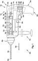
- FIG. 1 and FIG. 2 each show an embodiment of a hand tool 24a, 24b in a schematic representation with a hand tool device 10a, 10b according to the invention.
- a housing 32a, 32b of the power tool 24a, 24b shown broken so that the power tool device 10a, 10b in the interior of the power tool 24a, 24b is visible.
- FIG. 1 shows a handheld power tool device 10a with a percussion device 12a.
- the impact device 12a has an electric motor 34a, a crank mechanism 36a, a conversion element 38a, a drive piston 40a, a hammer tube 42a, a compression chamber 28a, a beater 44a, and a striker 46a.
- the electric motor 34a is rotatably connected to the crank mechanism 36a.
- the crank mechanism 36a converts a rotational movement of a shaft 50a of the electric motor 34a by means of the conversion element 38a into an oscillating linear movement 52a of the drive piston 40a along a main working direction 54a of the handheld power tool 24a.
- the drive piston 40a is guided by the hammer tube 42a.
- the hammer tube 42a surrounds the drive piston 40a in a circle.
- the driving piston 40a drives the racket 44a by means of a pressure of a gas, by means of air, in the compression chamber 28a.
- the beater 44a is disposed in the main working direction 54a in the hammer pipe 42a as viewed from the driving piston 40a and is also guided by the hammer pipe 42a.
- the racket 44a can, driven by the pressure, be moved between the drive piston 40a and the firing pin 46a. When the racket 44a hits the striker 46a, the racket 44a transmits a pulse to the striker 46a.
- the striker 46a is coupled to a tool 56a which is releasably disposed in a tool chuck 48a.
- the tool 56a is formed in this embodiment as a spiral drill bit. Other tools 56a that would appear meaningful to a person skilled in the art would also be possible.
- the electric motor 34a rotates the tool 56a about a rotation axis 60a by means of a shaft 58a.
- the rotation axis 60a is parallel to the main working direction 54a.
- Other configurations of the percussion mechanism that seem appropriate to a person skilled in the art, in particular for a percussion hammer, are possible.
- the impact device 12a has a control device 14a, which is intended to control two impact characteristics.
- the control device 14a is arranged, apart from two sensors 22a, 26a and a selector element 30a, together with power electronics 62a, which supply the electric motor 34a, on a circuit board 64a in a main handle-forming shaft 66a of the L-shaped housing 32a.
- the control device 14a has a computing unit 16a, which is designed as a microcontroller.
- the arithmetic unit 16a executes three routines during operation.
- a first calculation routine 68a is provided to determine a feedback variable of the impact characteristics depending on a parameter.
- a pressure waveform in the compression chamber 28a and an acceleration course of the housing 32a serve as parameters.
- a second calculation routine 70a determines an operating point that serves as a control reference.
- a control routine 18a is provided to control the impact characteristic to be controlled with respect to the operating point.
- the control routine 18a has calculation methods not shown in more detail, e.g. for a PID controller and a comparison method.
- the regulating device 14a has a measuring device 20a which is provided to detect two parameters.
- the measuring device 20a has an acceleration sensor 22a.
- the acceleration sensor 22a is disposed on the board 64a coupled to the housing 32a.
- the acceleration parameter contains information about a Vibration of the housing 32 a and information about an energy that reflects a workpiece not shown in detail. The vibrations are measured by the position of the acceleration sensor 22a close to an operator, not shown.
- the measuring device 20a For detecting the pressure parameter in the compression chamber 28a of the impact device 12a, the measuring device 20a has a pressure sensor 26a.
- the pressure sensor 26a is arranged in an end face 72a of the drive piston 40a pointing in the main working direction 54a and is connected to the circuit board 64a by means of an information carrier, in this case an electrical line 74a. At this point, the pressure sensor 26a can permanently detect the pressure curve in the compression chamber 28a.
- the pressure parameter includes information about energy that reflects a workpiece and information about the vibration of the housing 32a.
- control device 14a has two control modes. Depending on the control mode, different operating points are used for the control. The different operating points are optimized for different effects. One of the control modes is intended to control to a vibration optimized operating point. The other control mode is intended to control an impact optimized operating point.
- the handheld power tool device 10a has the selection element 30a, which provides the operator with a choice of the control modes.
- the selection element 30a is designed as a switch and arranged on a lower side 76a of the housing 32a.
- FIG. 2 a further embodiment of the invention is shown.
- the letter a in the reference numerals of the embodiment in the FIG. 1 by the letter b in the reference numerals of the embodiment in the FIG. 2 replaced.
- the following description is essentially limited to the differences from the embodiment in FIG. 1 , wherein with respect to the same components, features and functions on the description of the embodiment in the FIG. 1 can be referenced.
- FIG. 12 shows a handheld power tool apparatus 10b in which a pressure sensor 26b, unlike the first embodiment, is disposed on a side 78b of a hammer tube 42b.
- the pressure sensor 26b is connected to a compression chamber 28b of the hammer tube 42b by means of a pressure passage 82b, the pressure passage 82b being disposed in a guide portion of the hammer tube 42b in which a beater 44b of a beater 12b is guided so that the beater 44b is at least at an operating point closes the pressure channel 82b and thus protects the pressure sensor 26b.
- the pressure channel 82b is arranged so far away from a drive piston 40b that the pressure sensor 26b is protected from the maximum of the pressure curve during a maximum of the pressure curve by a racket 44b.
- the maximum of the pressure curve occurs when a distance 80b between the beater 44b and the drive piston 40b is minimal.
- the beater 44b closes an opening 82b in the hammer tube 42b to the pressure sensor 26b.
- the drive piston 40b can also close the pressure channel 82b.
Landscapes
- Engineering & Computer Science (AREA)
- Mechanical Engineering (AREA)
- Percussive Tools And Related Accessories (AREA)
Claims (3)
- Ensemble d'outil manuel motorisé présentant au moins un ensemble de percussion (12a, 12b), l'ensemble de percussion (12a, 12b) présentant un ensemble de régulation (14a, 14b) prévu pour réguler une grandeur caractéristique de percussion se rapportant aux vibrations et à l'effet de percussion,
l'ensemble de régulation (14a, 14b) présentant au moins un ensemble de mesure (20a, 20b) qui présente au moins un capteur d'accélération (22a, 22b) prévu pour saisir au moins un paramètre d'accélération d'un outil manuel motorisé (24a, 24b),
le paramètre d'accélération étant formé par la mesure de l'évolution de l'accélération suivant au moins un axe parallèle à une direction principale de travail de l'outil manuel motorisé (24a, 24b),
l'ensemble de régulation (14a, 14b) présentant une unité de calcul (16a, 16b),
caractérisé en ce que
l'ensemble de mesure (20a, 20b) présente en outre au moins un capteur de pression (26a, 26b) prévu pour saisir au moins une partie du temps un paramètre de pression qui règne dans une chambre de compression (28a, 28b) de l'ensemble de percussion (12a, 12b),
en ce que l'unité de calcul (16a, 16b) est prévue au moins pour déterminer au moins une grandeur de renvoi à la grandeur caractéristique de percussion en fonction d'au moins le paramètre d'accélération et le paramètre de pression,
en ce que l'ensemble de régulation (14a, 14b) présente une routine de régulation (18a, 18b) prévue pour réguler au moins la grandeur caractéristique de percussion par rapport à au moins un point de travail,
en ce que l'ensemble de régulation (14a, 14b) présente au moins deux modes de régulation prévus pour délivrer chacun au moins un point de travail et
en ce que l'ensemble de régulation (14a, 14b) est prévu pour réguler un point de travail optimisé en termes de vibrations dans l'un des modes de régulation, et pour réguler un point de travail en termes de percussion dans l'un des modes de régulation. - Ensemble d'outil manuel motorisé selon au moins la revendication 1, caractérisé par un élément de sélection (30a, 30b) qui offre à un opérateur une possibilité de sélection du mode de régulation.
- Outil manuel motorisé présentant un ensemble (10a, 10b) d'outil manuel motorisé selon l'une des revendications 1 et 2.
Applications Claiming Priority (1)
| Application Number | Priority Date | Filing Date | Title |
|---|---|---|---|
| DE102008044044A DE102008044044A1 (de) | 2008-11-25 | 2008-11-25 | Handwerkzeugmaschinenvorrichtung |
Publications (2)
| Publication Number | Publication Date |
|---|---|
| EP2189249A1 EP2189249A1 (fr) | 2010-05-26 |
| EP2189249B1 true EP2189249B1 (fr) | 2018-01-17 |
Family
ID=41278131
Family Applications (1)
| Application Number | Title | Priority Date | Filing Date |
|---|---|---|---|
| EP09171301.6A Not-in-force EP2189249B1 (fr) | 2008-11-25 | 2009-09-25 | Dispositif de machine-outil et machine-outil |
Country Status (3)
| Country | Link |
|---|---|
| EP (1) | EP2189249B1 (fr) |
| CN (1) | CN101733735B (fr) |
| DE (1) | DE102008044044A1 (fr) |
Families Citing this family (16)
| Publication number | Priority date | Publication date | Assignee | Title |
|---|---|---|---|---|
| DE102012206451B4 (de) * | 2012-04-19 | 2020-12-10 | Hilti Aktiengesellschaft | Handwerkzeugmaschine |
| WO2013174641A1 (fr) * | 2012-05-25 | 2013-11-28 | Robert Bosch Gmbh | Unité de percussion |
| DE102012208870A1 (de) * | 2012-05-25 | 2013-11-28 | Robert Bosch Gmbh | Schlagwerkeinheit |
| CN103573183A (zh) * | 2012-08-06 | 2014-02-12 | 周飞 | 一种改进的气动冲击钻 |
| DE102013208902B4 (de) | 2013-05-14 | 2023-12-14 | Robert Bosch Gmbh | Handwerkzeugvorrichtung |
| DE102013212635B4 (de) * | 2013-06-28 | 2024-05-08 | Robert Bosch Gmbh | Handwerkzeugmaschine |
| DE102014207434A1 (de) * | 2014-04-17 | 2015-10-22 | Robert Bosch Gmbh | Verfahren zum Betreiben einer Handwerkzeugmaschine, Handwerkzeugmaschine |
| DE102014212253A1 (de) * | 2014-06-26 | 2015-12-31 | Robert Bosch Gmbh | Schlagwerkvorrichtung |
| EP3028820A1 (fr) * | 2014-12-03 | 2016-06-08 | HILTI Aktiengesellschaft | Machine-outils portative et procédé de commande associé |
| EP3028821A1 (fr) * | 2014-12-03 | 2016-06-08 | HILTI Aktiengesellschaft | Procédé de contrôle pour une machine-outils portative |
| DE102015205172A1 (de) * | 2015-03-23 | 2016-09-29 | Robert Bosch Gmbh | Werkzeugmaschine, insbesondere Handwerkzeugmaschine, mit einer motorischen Antriebseinheit und mit zumindest einer Sensorvorrichtung |
| EP3290721A1 (fr) | 2016-08-30 | 2018-03-07 | HILTI Aktiengesellschaft | Capteur de distance sur un bec d'ancre |
| CN108543979A (zh) * | 2018-04-20 | 2018-09-18 | 郑牡兰 | 一种先进的模具设计和制造技术设备 |
| CN108637322A (zh) * | 2018-04-20 | 2018-10-12 | 李晓梅 | 一种数控加工设备 |
| CN108547471A (zh) * | 2018-04-20 | 2018-09-18 | 王云龙 | 一种安全消防组件 |
| CN110774236B (zh) * | 2019-11-20 | 2021-07-27 | 山东奥德燃气设备制造有限公司 | 一种压力可调的气动冲击工具 |
Family Cites Families (8)
| Publication number | Priority date | Publication date | Assignee | Title |
|---|---|---|---|---|
| DE2832169A1 (de) * | 1978-07-21 | 1980-01-31 | Hilti Ag | Motorisch betriebener bohrhammer |
| US6508315B1 (en) * | 2001-06-07 | 2003-01-21 | Steven James Lindsay | Small impact power tool |
| US6691798B1 (en) * | 2002-06-19 | 2004-02-17 | Steven James Lindsay | Variable hand pressure activated power tool |
| DE10309012B3 (de) * | 2003-03-01 | 2004-08-12 | Hilti Ag | Steuerverfahren einer axial schlagenden und drehenden Elektrohandwerkzeugmaschine |
| DE10316844A1 (de) * | 2003-04-11 | 2004-11-04 | Hilti Ag | Steuerung einer Elektrohandwerkzeugmaschine |
| GB2411375B (en) * | 2004-02-26 | 2008-04-09 | South West Highways Ltd | Vibration reduction system |
| DE102007000488A1 (de) * | 2007-09-12 | 2009-03-19 | Hilti Aktiengesellschaft | Handwerkzeugmaschine mit Luftfederschlagswerk, Linearmotor und Steuerverfahren |
| GB0804967D0 (en) * | 2008-03-18 | 2008-04-16 | Black & Decker Inc | Powered hammer with a vibration dampening mechanism |
-
2008
- 2008-11-25 DE DE102008044044A patent/DE102008044044A1/de not_active Withdrawn
-
2009
- 2009-09-25 EP EP09171301.6A patent/EP2189249B1/fr not_active Not-in-force
- 2009-11-24 CN CN200910225001.5A patent/CN101733735B/zh not_active Expired - Fee Related
Non-Patent Citations (1)
| Title |
|---|
| None * |
Also Published As
| Publication number | Publication date |
|---|---|
| EP2189249A1 (fr) | 2010-05-26 |
| DE102008044044A1 (de) | 2010-05-27 |
| CN101733735A (zh) | 2010-06-16 |
| CN101733735B (zh) | 2014-12-03 |
Similar Documents
| Publication | Publication Date | Title |
|---|---|---|
| EP2189249B1 (fr) | Dispositif de machine-outil et machine-outil | |
| EP2729280B1 (fr) | Dispositif à percussion | |
| DE102013224759A1 (de) | Werkzeugmaschinenvorrichtung | |
| CH702274A2 (de) | Handwerkzeugmaschinenvorrichtung. | |
| EP3056317B1 (fr) | Machine-outil portative | |
| DE102013212635A1 (de) | Handwerkzeugmaschinenvorrichtung | |
| EP2855098B1 (fr) | Unité de percussion | |
| EP2448715A1 (fr) | Machine-outil portative | |
| DE102013212626B4 (de) | Handwerkzeugmaschinenvorrichtung | |
| DE102009027444A1 (de) | Handwerkzeugmaschine | |
| EP3068585A1 (fr) | Machine-outil à main | |
| EP4377049A1 (fr) | Procédé de commande en boucle ouverte et en boucle fermée d'une machine-outil | |
| DE10209293A1 (de) | Pneumatisches Schlagwerk | |
| DE102010001683A1 (de) | Handwerkzeugmaschinenvorrichtung | |
| DE102020206450A1 (de) | Handwerkzeugmaschine | |
| DE102015006318A1 (de) | Kraftwerkzeug | |
| DE60103956T2 (de) | Schlagbohrmaschine | |
| WO2016059017A1 (fr) | Machine-outil portative de burinage | |
| DE102016218775A1 (de) | Handwerkzeugmaschinensystem | |
| EP4101595A1 (fr) | Procédé de détermination d'une propriété d'un outil, ainsi que machine-outil mobile | |
| DE102013211242A1 (de) | Schlagwerksteuer- und/oder -regelvorrichtung | |
| DE102016214844A1 (de) | Verfahren zu einem Betrieb einer tragbaren Werkzeugmaschine | |
| WO2012072326A1 (fr) | Mécanisme de percussion à marteau | |
| DE102013212592A1 (de) | Handwerkzeugmaschinenschaltvorrichtung | |
| EP3808506A1 (fr) | Machine-outil manuelle |
Legal Events
| Date | Code | Title | Description |
|---|---|---|---|
| PUAI | Public reference made under article 153(3) epc to a published international application that has entered the european phase |
Free format text: ORIGINAL CODE: 0009012 |
|
| AK | Designated contracting states |
Kind code of ref document: A1 Designated state(s): AT BE BG CH CY CZ DE DK EE ES FI FR GB GR HR HU IE IS IT LI LT LU LV MC MK MT NL NO PL PT RO SE SI SK SM TR |
|
| AX | Request for extension of the european patent |
Extension state: AL BA RS |
|
| 17P | Request for examination filed |
Effective date: 20101126 |
|
| 17Q | First examination report despatched |
Effective date: 20160209 |
|
| GRAP | Despatch of communication of intention to grant a patent |
Free format text: ORIGINAL CODE: EPIDOSNIGR1 |
|
| INTG | Intention to grant announced |
Effective date: 20170822 |
|
| RAP1 | Party data changed (applicant data changed or rights of an application transferred) |
Owner name: ROBERT BOSCH GMBH |
|
| GRAS | Grant fee paid |
Free format text: ORIGINAL CODE: EPIDOSNIGR3 |
|
| GRAA | (expected) grant |
Free format text: ORIGINAL CODE: 0009210 |
|
| AK | Designated contracting states |
Kind code of ref document: B1 Designated state(s): AT BE BG CH CY CZ DE DK EE ES FI FR GB GR HR HU IE IS IT LI LT LU LV MC MK MT NL NO PL PT RO SE SI SK SM TR |
|
| REG | Reference to a national code |
Ref country code: GB Ref legal event code: FG4D Free format text: NOT ENGLISH |
|
| REG | Reference to a national code |
Ref country code: CH Ref legal event code: EP |
|
| REG | Reference to a national code |
Ref country code: IE Ref legal event code: FG4D Free format text: LANGUAGE OF EP DOCUMENT: GERMAN |
|
| REG | Reference to a national code |
Ref country code: AT Ref legal event code: REF Ref document number: 964100 Country of ref document: AT Kind code of ref document: T Effective date: 20180215 |
|
| REG | Reference to a national code |
Ref country code: DE Ref legal event code: R096 Ref document number: 502009014678 Country of ref document: DE |
|
| REG | Reference to a national code |
Ref country code: NL Ref legal event code: MP Effective date: 20180117 |
|
| REG | Reference to a national code |
Ref country code: LT Ref legal event code: MG4D |
|
| PG25 | Lapsed in a contracting state [announced via postgrant information from national office to epo] |
Ref country code: NL Free format text: LAPSE BECAUSE OF FAILURE TO SUBMIT A TRANSLATION OF THE DESCRIPTION OR TO PAY THE FEE WITHIN THE PRESCRIBED TIME-LIMIT Effective date: 20180117 |
|
| PG25 | Lapsed in a contracting state [announced via postgrant information from national office to epo] |
Ref country code: ES Free format text: LAPSE BECAUSE OF FAILURE TO SUBMIT A TRANSLATION OF THE DESCRIPTION OR TO PAY THE FEE WITHIN THE PRESCRIBED TIME-LIMIT Effective date: 20180117 Ref country code: LT Free format text: LAPSE BECAUSE OF FAILURE TO SUBMIT A TRANSLATION OF THE DESCRIPTION OR TO PAY THE FEE WITHIN THE PRESCRIBED TIME-LIMIT Effective date: 20180117 Ref country code: NO Free format text: LAPSE BECAUSE OF FAILURE TO SUBMIT A TRANSLATION OF THE DESCRIPTION OR TO PAY THE FEE WITHIN THE PRESCRIBED TIME-LIMIT Effective date: 20180417 Ref country code: CY Free format text: LAPSE BECAUSE OF FAILURE TO SUBMIT A TRANSLATION OF THE DESCRIPTION OR TO PAY THE FEE WITHIN THE PRESCRIBED TIME-LIMIT Effective date: 20180117 Ref country code: HR Free format text: LAPSE BECAUSE OF FAILURE TO SUBMIT A TRANSLATION OF THE DESCRIPTION OR TO PAY THE FEE WITHIN THE PRESCRIBED TIME-LIMIT Effective date: 20180117 Ref country code: FI Free format text: LAPSE BECAUSE OF FAILURE TO SUBMIT A TRANSLATION OF THE DESCRIPTION OR TO PAY THE FEE WITHIN THE PRESCRIBED TIME-LIMIT Effective date: 20180117 |
|
| PG25 | Lapsed in a contracting state [announced via postgrant information from national office to epo] |
Ref country code: PL Free format text: LAPSE BECAUSE OF FAILURE TO SUBMIT A TRANSLATION OF THE DESCRIPTION OR TO PAY THE FEE WITHIN THE PRESCRIBED TIME-LIMIT Effective date: 20180117 Ref country code: GR Free format text: LAPSE BECAUSE OF FAILURE TO SUBMIT A TRANSLATION OF THE DESCRIPTION OR TO PAY THE FEE WITHIN THE PRESCRIBED TIME-LIMIT Effective date: 20180418 Ref country code: BG Free format text: LAPSE BECAUSE OF FAILURE TO SUBMIT A TRANSLATION OF THE DESCRIPTION OR TO PAY THE FEE WITHIN THE PRESCRIBED TIME-LIMIT Effective date: 20180417 Ref country code: LV Free format text: LAPSE BECAUSE OF FAILURE TO SUBMIT A TRANSLATION OF THE DESCRIPTION OR TO PAY THE FEE WITHIN THE PRESCRIBED TIME-LIMIT Effective date: 20180117 Ref country code: SE Free format text: LAPSE BECAUSE OF FAILURE TO SUBMIT A TRANSLATION OF THE DESCRIPTION OR TO PAY THE FEE WITHIN THE PRESCRIBED TIME-LIMIT Effective date: 20180117 Ref country code: IS Free format text: LAPSE BECAUSE OF FAILURE TO SUBMIT A TRANSLATION OF THE DESCRIPTION OR TO PAY THE FEE WITHIN THE PRESCRIBED TIME-LIMIT Effective date: 20180517 |
|
| REG | Reference to a national code |
Ref country code: FR Ref legal event code: PLFP Year of fee payment: 10 |
|
| PG25 | Lapsed in a contracting state [announced via postgrant information from national office to epo] |
Ref country code: MT Free format text: LAPSE BECAUSE OF FAILURE TO SUBMIT A TRANSLATION OF THE DESCRIPTION OR TO PAY THE FEE WITHIN THE PRESCRIBED TIME-LIMIT Effective date: 20180117 |
|
| REG | Reference to a national code |
Ref country code: DE Ref legal event code: R097 Ref document number: 502009014678 Country of ref document: DE |
|
| PG25 | Lapsed in a contracting state [announced via postgrant information from national office to epo] |
Ref country code: IT Free format text: LAPSE BECAUSE OF FAILURE TO SUBMIT A TRANSLATION OF THE DESCRIPTION OR TO PAY THE FEE WITHIN THE PRESCRIBED TIME-LIMIT Effective date: 20180117 Ref country code: RO Free format text: LAPSE BECAUSE OF FAILURE TO SUBMIT A TRANSLATION OF THE DESCRIPTION OR TO PAY THE FEE WITHIN THE PRESCRIBED TIME-LIMIT Effective date: 20180117 Ref country code: EE Free format text: LAPSE BECAUSE OF FAILURE TO SUBMIT A TRANSLATION OF THE DESCRIPTION OR TO PAY THE FEE WITHIN THE PRESCRIBED TIME-LIMIT Effective date: 20180117 |
|
| PLBE | No opposition filed within time limit |
Free format text: ORIGINAL CODE: 0009261 |
|
| STAA | Information on the status of an ep patent application or granted ep patent |
Free format text: STATUS: NO OPPOSITION FILED WITHIN TIME LIMIT |
|
| PG25 | Lapsed in a contracting state [announced via postgrant information from national office to epo] |
Ref country code: DK Free format text: LAPSE BECAUSE OF FAILURE TO SUBMIT A TRANSLATION OF THE DESCRIPTION OR TO PAY THE FEE WITHIN THE PRESCRIBED TIME-LIMIT Effective date: 20180117 Ref country code: SM Free format text: LAPSE BECAUSE OF FAILURE TO SUBMIT A TRANSLATION OF THE DESCRIPTION OR TO PAY THE FEE WITHIN THE PRESCRIBED TIME-LIMIT Effective date: 20180117 Ref country code: CZ Free format text: LAPSE BECAUSE OF FAILURE TO SUBMIT A TRANSLATION OF THE DESCRIPTION OR TO PAY THE FEE WITHIN THE PRESCRIBED TIME-LIMIT Effective date: 20180117 Ref country code: SK Free format text: LAPSE BECAUSE OF FAILURE TO SUBMIT A TRANSLATION OF THE DESCRIPTION OR TO PAY THE FEE WITHIN THE PRESCRIBED TIME-LIMIT Effective date: 20180117 |
|
| 26N | No opposition filed |
Effective date: 20181018 |
|
| PG25 | Lapsed in a contracting state [announced via postgrant information from national office to epo] |
Ref country code: SI Free format text: LAPSE BECAUSE OF FAILURE TO SUBMIT A TRANSLATION OF THE DESCRIPTION OR TO PAY THE FEE WITHIN THE PRESCRIBED TIME-LIMIT Effective date: 20180117 |
|
| PG25 | Lapsed in a contracting state [announced via postgrant information from national office to epo] |
Ref country code: MC Free format text: LAPSE BECAUSE OF FAILURE TO SUBMIT A TRANSLATION OF THE DESCRIPTION OR TO PAY THE FEE WITHIN THE PRESCRIBED TIME-LIMIT Effective date: 20180117 |
|
| REG | Reference to a national code |
Ref country code: BE Ref legal event code: MM Effective date: 20180930 |
|
| REG | Reference to a national code |
Ref country code: IE Ref legal event code: MM4A |
|
| PG25 | Lapsed in a contracting state [announced via postgrant information from national office to epo] |
Ref country code: LU Free format text: LAPSE BECAUSE OF NON-PAYMENT OF DUE FEES Effective date: 20180925 |
|
| PG25 | Lapsed in a contracting state [announced via postgrant information from national office to epo] |
Ref country code: IE Free format text: LAPSE BECAUSE OF NON-PAYMENT OF DUE FEES Effective date: 20180925 |
|
| PG25 | Lapsed in a contracting state [announced via postgrant information from national office to epo] |
Ref country code: BE Free format text: LAPSE BECAUSE OF NON-PAYMENT OF DUE FEES Effective date: 20180930 |
|
| PGFP | Annual fee paid to national office [announced via postgrant information from national office to epo] |
Ref country code: FR Payment date: 20190924 Year of fee payment: 11 |
|
| REG | Reference to a national code |
Ref country code: AT Ref legal event code: MM01 Ref document number: 964100 Country of ref document: AT Kind code of ref document: T Effective date: 20180925 |
|
| PGFP | Annual fee paid to national office [announced via postgrant information from national office to epo] |
Ref country code: GB Payment date: 20190924 Year of fee payment: 11 |
|
| PG25 | Lapsed in a contracting state [announced via postgrant information from national office to epo] |
Ref country code: AT Free format text: LAPSE BECAUSE OF NON-PAYMENT OF DUE FEES Effective date: 20180925 |
|
| PGFP | Annual fee paid to national office [announced via postgrant information from national office to epo] |
Ref country code: CH Payment date: 20190924 Year of fee payment: 11 |
|
| PG25 | Lapsed in a contracting state [announced via postgrant information from national office to epo] |
Ref country code: TR Free format text: LAPSE BECAUSE OF FAILURE TO SUBMIT A TRANSLATION OF THE DESCRIPTION OR TO PAY THE FEE WITHIN THE PRESCRIBED TIME-LIMIT Effective date: 20180117 |
|
| PG25 | Lapsed in a contracting state [announced via postgrant information from national office to epo] |
Ref country code: PT Free format text: LAPSE BECAUSE OF FAILURE TO SUBMIT A TRANSLATION OF THE DESCRIPTION OR TO PAY THE FEE WITHIN THE PRESCRIBED TIME-LIMIT Effective date: 20180117 Ref country code: HU Free format text: LAPSE BECAUSE OF FAILURE TO SUBMIT A TRANSLATION OF THE DESCRIPTION OR TO PAY THE FEE WITHIN THE PRESCRIBED TIME-LIMIT; INVALID AB INITIO Effective date: 20090925 |
|
| PG25 | Lapsed in a contracting state [announced via postgrant information from national office to epo] |
Ref country code: MK Free format text: LAPSE BECAUSE OF NON-PAYMENT OF DUE FEES Effective date: 20180117 |
|
| REG | Reference to a national code |
Ref country code: CH Ref legal event code: PL |
|
| GBPC | Gb: european patent ceased through non-payment of renewal fee |
Effective date: 20200925 |
|
| PG25 | Lapsed in a contracting state [announced via postgrant information from national office to epo] |
Ref country code: FR Free format text: LAPSE BECAUSE OF NON-PAYMENT OF DUE FEES Effective date: 20200930 |
|
| PG25 | Lapsed in a contracting state [announced via postgrant information from national office to epo] |
Ref country code: LI Free format text: LAPSE BECAUSE OF NON-PAYMENT OF DUE FEES Effective date: 20200930 Ref country code: GB Free format text: LAPSE BECAUSE OF NON-PAYMENT OF DUE FEES Effective date: 20200925 Ref country code: CH Free format text: LAPSE BECAUSE OF NON-PAYMENT OF DUE FEES Effective date: 20200930 |
|
| PGFP | Annual fee paid to national office [announced via postgrant information from national office to epo] |
Ref country code: DE Payment date: 20231124 Year of fee payment: 15 |
|
| REG | Reference to a national code |
Ref country code: DE Ref legal event code: R084 Ref document number: 502009014678 Country of ref document: DE |
|
| REG | Reference to a national code |
Ref country code: DE Ref legal event code: R119 Ref document number: 502009014678 Country of ref document: DE |
|
| PG25 | Lapsed in a contracting state [announced via postgrant information from national office to epo] |
Ref country code: DE Free format text: LAPSE BECAUSE OF NON-PAYMENT OF DUE FEES Effective date: 20250401 |