EP2189256B1 - Positionssteuerverfahren und positionssteuervorrichtung - Google Patents
Positionssteuerverfahren und positionssteuervorrichtung Download PDFInfo
- Publication number
- EP2189256B1 EP2189256B1 EP08831023.0A EP08831023A EP2189256B1 EP 2189256 B1 EP2189256 B1 EP 2189256B1 EP 08831023 A EP08831023 A EP 08831023A EP 2189256 B1 EP2189256 B1 EP 2189256B1
- Authority
- EP
- European Patent Office
- Prior art keywords
- posture
- distance
- processing unit
- distance measuring
- measurement
- Prior art date
- Legal status (The legal status is an assumption and is not a legal conclusion. Google has not performed a legal analysis and makes no representation as to the accuracy of the status listed.)
- Active
Links
Images


Classifications
-
- B—PERFORMING OPERATIONS; TRANSPORTING
- B25—HAND TOOLS; PORTABLE POWER-DRIVEN TOOLS; MANIPULATORS
- B25J—MANIPULATORS; CHAMBERS PROVIDED WITH MANIPULATION DEVICES
- B25J13/00—Controls for manipulators
- B25J13/08—Controls for manipulators by means of sensing devices, e.g. viewing or touching devices
- B25J13/088—Controls for manipulators by means of sensing devices, e.g. viewing or touching devices with position, velocity or acceleration sensors
- B25J13/089—Determining the position of the robot with reference to its environment
-
- B—PERFORMING OPERATIONS; TRANSPORTING
- B25—HAND TOOLS; PORTABLE POWER-DRIVEN TOOLS; MANIPULATORS
- B25J—MANIPULATORS; CHAMBERS PROVIDED WITH MANIPULATION DEVICES
- B25J9/00—Program-controlled manipulators
- B25J9/16—Program controls
- B25J9/1679—Program controls characterised by the tasks executed
- B25J9/1684—Tracking a line or surface by means of sensors
-
- F—MECHANICAL ENGINEERING; LIGHTING; HEATING; WEAPONS; BLASTING
- F22—STEAM GENERATION
- F22B—METHODS OF STEAM GENERATION; STEAM BOILERS
- F22B37/00—Component parts or details of steam boilers
- F22B37/002—Component parts or details of steam boilers specially adapted for nuclear steam generators, e.g. maintenance, repairing or inspecting equipment not otherwise provided for
- F22B37/003—Maintenance, repairing or inspecting equipment positioned in or via the headers
- F22B37/005—Positioning apparatus specially adapted therefor
-
- G—PHYSICS
- G21—NUCLEAR PHYSICS; NUCLEAR ENGINEERING
- G21D—NUCLEAR POWER PLANT
- G21D1/00—Details of nuclear power plant
- G21D1/006—Details of nuclear power plant primary side of steam generators
-
- B—PERFORMING OPERATIONS; TRANSPORTING
- B24—GRINDING; POLISHING
- B24C—ABRASIVE OR RELATED BLASTING WITH PARTICULATE MATERIAL
- B24C1/00—Methods for use of abrasive blasting for producing particular effects; Use of auxiliary equipment in connection with such methods
- B24C1/10—Methods for use of abrasive blasting for producing particular effects; Use of auxiliary equipment in connection with such methods for compacting surfaces, e.g. shot-peening
-
- G—PHYSICS
- G21—NUCLEAR PHYSICS; NUCLEAR ENGINEERING
- G21C—NUCLEAR REACTORS
- G21C17/00—Monitoring; Testing ; Maintaining
- G21C17/017—Inspection or maintenance of pipe-lines or tubes in nuclear installations
-
- Y—GENERAL TAGGING OF NEW TECHNOLOGICAL DEVELOPMENTS; GENERAL TAGGING OF CROSS-SECTIONAL TECHNOLOGIES SPANNING OVER SEVERAL SECTIONS OF THE IPC; TECHNICAL SUBJECTS COVERED BY FORMER USPC CROSS-REFERENCE ART COLLECTIONS [XRACs] AND DIGESTS
- Y02—TECHNOLOGIES OR APPLICATIONS FOR MITIGATION OR ADAPTATION AGAINST CLIMATE CHANGE
- Y02E—REDUCTION OF GREENHOUSE GAS [GHG] EMISSIONS, RELATED TO ENERGY GENERATION, TRANSMISSION OR DISTRIBUTION
- Y02E30/00—Energy generation of nuclear origin
-
- Y—GENERAL TAGGING OF NEW TECHNOLOGICAL DEVELOPMENTS; GENERAL TAGGING OF CROSS-SECTIONAL TECHNOLOGIES SPANNING OVER SEVERAL SECTIONS OF THE IPC; TECHNICAL SUBJECTS COVERED BY FORMER USPC CROSS-REFERENCE ART COLLECTIONS [XRACs] AND DIGESTS
- Y02—TECHNOLOGIES OR APPLICATIONS FOR MITIGATION OR ADAPTATION AGAINST CLIMATE CHANGE
- Y02E—REDUCTION OF GREENHOUSE GAS [GHG] EMISSIONS, RELATED TO ENERGY GENERATION, TRANSMISSION OR DISTRIBUTION
- Y02E30/00—Energy generation of nuclear origin
- Y02E30/30—Nuclear fission reactors
Definitions
- the present invention relates to a posture control method and a posture control device that control a posture of a processing unit relative to a process surface of a round pipe.
- a tip tool guide apparatus that includes a rotation supporting unit arranged upright in a water chamber of a steam generator, a slide table provided in the rotation supporting unit, a manipulator mounted on the slide table, and a tip tool (processing unit) fixed to the end of the manipulator has been known (see Patent Document 1).
- the tip tool guide apparatus moves (guides) the tip tool along a shot peening area of an inner peripheral surface of a pipe base provided in the water chamber by controlling the manipulator. At this time, the tip tool is pressed against the inner peripheral surface by the manipulator, and the posture of the tip tool follows the inner peripheral surface of the pipe base. In other words, the posture of the tip tool is controlled to have a predetermined posture by being pressed against and brought closely in contact with the inner peripheral surface by the manipulator.
- the rigidity of the tip tool guide apparatus cannot withstand the reaction force from the inner peripheral surface. Accordingly, the tip tool guide apparatus may bend slightly or be twisted, thereby making the tip tool supposed to have pressed against and brought closely in contact with the inner peripheral surface, to rise slightly. In this case, the raised tip tool may cause process failure.
- the rigidity of the tip tool guide apparatus may be increased to solve the problem, but the tip tool guide apparatus is designed to be brought into the water chamber. Due to the design restriction, it is difficult to increase the rigidity of the tip tool guide apparatus larger than a predetermined rigidity.
- the present invention is intended to provide a posture control method and a posture control device that allow the processing unit to face the process surface of the round pipe at a desired posture by simple control.
- a posture control method that controls a posture of a processing unit relative to a process surface by measuring a gap distance between the processing unit that performs processing on an inner peripheral surface or an outer peripheral surface of a round pipe and the process surface of the round pipe to be processed by the processing unit, includes: disposing a plurality of distance measuring units in the processing unit, and at least four given distance measuring units being arranged to face the process surface in a positional relationship of four apexes of a rectangle; controlling the posture of the processing unit in a rotational direction about a roll axis, based on a difference between a first total distance obtained by adding distances measured by two out of the four given distance measuring units located in one diagonal position, and a second total distance obtained by adding measurement distances measured by the other two distance measuring units located in the other diagonal position.
- the process surface that the distance measuring units face is divided into four virtual partitioned areas, based on a first virtual boundary line extended in a pipe axis direction of the process surface and a second virtual boundary line extended in a perpendicular direction perpendicular to the first virtual boundary line, and the four virtual partitioned areas are composed of a first virtual partitioned area, a second virtual partitioned area adjacent to the first virtual partitioned area in the pipe axis direction, a third virtual partitioned area adjacent to the first virtual partitioned area in the perpendicular direction, and a fourth virtual partitioned area adjacent to the second virtual partitioned area in the perpendicular direction and also adjacent to the third virtual partitioned area in the pipe axis direction.
- the posture control method further includes: positioning measuring units that, among the four given distance measuring units, makes a first distance measuring unit face the first virtual partitioned area, makes a second distance measuring unit face the second virtual partitioned area, makes a third distance measuring unit face the third virtual partitioned area, and makes a fourth distance measuring unit face the fourth virtual partitioned area.
- the controlling the posture controls the posture of the processing unit in the rotational direction about the roll axis, based on a difference between the first total distance obtained by adding a second measurement distance measured by the second distance measuring unit and a third measurement distance measured by the third distance measuring unit, and the second total distance obtained by adding a first measurement distance measured by the first distance measuring unit and a fourth measurement distance measured by the fourth distance measuring unit.
- a posture control method that controls a posture of a processing unit relative to a process surface by measuring a gap distance between the processing unit that performs processing on an inner peripheral surface or an outer peripheral surface of a round pipe, and the process surface of the round pipe to be processed by the processing unit includes: determining positions of measuring units and controlling posture of processing unit.
- the determining positions of measuring units includes: disposing four distance measuring units arranged to face the process surface in a positional relationship of four apexes of a rectangle in the processing unit; defining four virtual partitioned areas on the process surface that the four distance measuring units face, based on a first virtual boundary line extended in a pipe axis direction of the process surface and a second virtual boundary line extended in a perpendicular direction perpendicular to the first virtual boundary line, the four virtual partitioned areas being composed of a first virtual partitioned area, a second virtual partitioned area adjacent to the first virtual partitioned area in the pipe axis direction, a third virtual partitioned area adjacent to the first virtual partitioned area in the perpendicular direction, and a fourth virtual partitioned area adjacent to the second virtual partitioned area in the perpendicular direction and also adjacent to the third virtual partitioned area in the pipe axis direction, positioning measuring units that, among the four distance measuring units, makes a first distance measuring unit face the first virtual partitioned area,
- the controlling posture of processing unit includes: controlling the posture of the processing unit in a rotational direction about a pitch axis, based on a difference obtained by subtracting a second measurement distance measured by the second distance measuring unit from a first measurement distance measured by the first distance measuring unit, and a difference obtained by subtracting a fourth measurement distance measured by the fourth distance measuring unit from a third measurement distance measured by the third distance measuring unit, controlling the posture of the processing unit in a rotational direction about a yaw axis, based on a difference obtained by subtracting the third measurement distance from the first measurement distance, and a difference obtained by subtracting the fourth measurement distance from the second measurement distance, and controlling the posture of the processing unit in a rotational direction about a roll axis, based on a difference between a first total distance obtained by adding the second measurement distance and the third measurement distance, and a second total distance obtained by adding the first measurement distance and the fourth measurement distance.
- the processing unit is formed to perform a following-operation in which the processing unit moves along the process surface with the posture thereof following the process surface, and the posture of the processing unit is feedback controlled by executing the controlling the posture in real time during the following-operation performed by the processing unit.
- the posture control method further includes setting a gap distance between the processing unit and the process surface to be a set distance, based on a difference obtained by subtracting the set distance that is set in advance from an average distance of the first measurement distance, the second measurement distance, the third measurement distance, and the fourth measurement distance.
- the controlling the posture controls the posture of the processing unit, based on an initial posture of the processing unit about the pitch axis set in advance, an initial posture of the processing unit about the yaw axis set in advance, and an initial posture of the processing unit about the roll axis set in advance.
- the four given distance measuring units are arranged to face the process surface in a positional relationship of four apexes of a rectangle, and the posture controlling unit controls the posture of the processing unit in a rotational direction about a roll axis, based on a difference between a first total distance obtained by adding measurement distances measured by two distance measuring units located in one diagonal position among the four given distance measuring units, and a second total distance obtained by adding measurement distances measured by two distance measuring units located in another diagonal position.
- the process surface that the distance measuring units face is divided into four virtual partitioned areas, based on a first virtual boundary line extended in a pipe axis direction of the process surface, and a second virtual boundary line extended in a perpendicular direction perpendicular to the first virtual boundary line, the four virtual partitioned areas are composed of a first virtual partitioned area, a second virtual partitioned area adjacent to the first virtual partitioned area in the pipe axis direction, a third virtual partitioned area adjacent to the first virtual partitioned area in the perpendicular direction, and a fourth virtual partitioned area adjacent to the second virtual partitioned area in the perpendicular direction and also adjacent to the third virtual partitioned area in the pipe axis direction, among the four given distance measuring units, a first distance measuring unit is made to face the first virtual partitioned area, a second distance measuring unit is made to face the second virtual partitioned area, a third distance measuring unit is made to face the third virtual partitioned area, and
- the four distance measuring units are arranged to face the process surface in a positional relationship of four apexes of a rectangle, the process surface that the four distance measuring units face is divided into four virtual partitioned areas, based on a first virtual boundary line extended in a pipe axis direction of the process surface and a second virtual boundary line extended in a perpendicular direction perpendicular to the first virtual boundary line, the four virtual partitioned areas are composed of a first virtual partitioned area, a second virtual partitioned area adjacent to the first virtual partitioned area in the pipe axis direction, a third virtual partitioned area adjacent to the first virtual partitioned area in the perpendicular direction, and a fourth virtual partitioned area adjacent to the second virtual partitioned area in the perpendicular direction and also adjacent to the third virtual partitioned area in the pipe axis direction, among the four distance measuring units, a first distance measuring unit is made to face the first virtual partitioned area, a second distance measuring unit is made to face the second virtual partitioned
- the posture controlling unit controls the posture of the processing unit in a rotational direction about a pitch axis, based on a difference obtained by subtracting a second measurement distance measured by the second distance measuring unit from a first measurement distance measured by the first distance measuring unit, and a difference obtained by subtracting a fourth measurement distance measured by the fourth distance measuring unit from a third measurement distance measured by the third distance measuring unit, controls the posture of the processing unit in a rotational direction about a yaw axis, based on a difference obtained by subtracting the third measurement distance from the first measurement distance, and a difference obtained by subtracting the fourth measurement distance from the second measurement distance, and controls the posture of the processing unit in a rotational direction about a roll axis, based on a difference between a first total distance obtained by adding the second measurement distance and the third measurement distance, and a second total distance obtained by adding the first measurement distance and the fourth measurement distance.
- the processing unit is formed to perform a following-operation in which the processing unit moves along the process surface with the posture thereof following the process surface, and the posture controlling unit feedback controls the posture of the processing unit by executing the controlling the posture in real time during the following-operation performed by the processing unit.
- the posture controlling unit so controls the posture of the processing unit that a gap distance between the processing unit and the process surface is a set distance, based on a difference obtained by subtracting the set distance that is set in advance from an average distance of the first measurement distance, the second measurement distance, the third measurement distance, and the fourth measurement distance.
- the posture controlling unit controls the posture of the processing unit, based on an initial posture of the processing unit about the pitch axis set in advance, an initial posture of the processing unit about the yaw axis set in advance, and an initial posture of the processing unit about the roll axis set in advance.
- the posture of the processing unit is controlled about a roll axis, in a simple manner.
- four given distance measuring units are used, for example, even if the posture of the processing unit is shifted by an angle component in the rotational direction about a pitch axis, or shifted by an angle component in the rotational direction about a yaw axis, the posture of the processing unit can be suitably controlled about the roll axis, without being affected by the displacement.
- To control the posture of the processing unit about the roll axis at least four distance measuring units are to be used. However, depending on the situation, more than four distance measuring units may be used.
- the four given distance measuring units are suitably made to face four virtual partitioned areas.
- two distance measuring units such as a second distance measuring unit and a third distance measuring unit, or a first distance measuring unit and a fourth distance measuring unit located in a diagonal position do not overlap with a first virtual boundary line or a second virtual boundary line, or a plurality of distance measuring sensors does not face one virtual partitioned area. Accordingly, the direction to return the displacement of the posture of the processing unit about the roll axis to a predetermined posture can be obtained, from a difference between a first total distance and a second total distance. As a result, the posture of the processing unit can be correctly controlled about the roll axis.
- the posture of the processing unit can be controlled about the pitch axis, the yaw axis, and the roll axis, in a simple manner.
- the processing unit is made to face a process surface of a round pipe with the posture thereof following the process surface. Accordingly, by controlling the posture of the processing unit to follow the process surface, the tip tool need not be pressed against the inner peripheral surface (process surface) by the manipulator as in the conventional method. Because the reaction force from the process surface is not increased, the rigidity of the tip tool guide apparatus need not be increased.
- the processing unit includes, for example, a tip tool used for shot peening, a testing device using ultrasound wave for testing, an imaging camera for a microscope, or a processing device for cutting and slicing.
- the cross-section of the round pipe may be round, elliptical, oval, or the like.
- the posture of the processing unit can be feedback controlled. Accordingly, even if the processing unit is moved, the posture of the processing unit can always be maintained to follow the process surface.
- a gap distance between the processing unit and the process surface is set at a desired distance. Accordingly, the processing unit can perform processing, while maintaining the gap at a desired distance.
- a posture control method according to claim 6 and a posture control device according to claim 12, by arranging the processing unit to a preset initial posture, the processing unit can perform processing on the process surface, while maintaining the initial posture thereof.
- Fig. 1 is a perspective view of a tip tool guide apparatus according to a present embodiment.
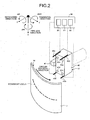
- Fig. 2 is a schematic of a tip tool.
- Fig. 3 is a schematic for explaining a measuring sensor positioning step.
- a tip tool guide apparatus 10 is provided in a water chamber 1 in a steam generator of a pressurized water reactor type nuclear power plant.
- the tip tool guide apparatus 10 performs various processes on an inner peripheral surface (hereinafter, referred to as a process surface 4) of a welded portion between a pipe base 2 provided at a lower portion of the water chamber 1 and a cylindrical pipe (round pipe) 3 connected to the pipe base 2.
- the tip tool guide apparatus 10 includes a rotation supporting unit 14 arranged upright from the bottom to the ceiling of the water chamber 1, a slide table 15 that has a sliding mechanism and detachably connected to the rotation supporting unit 14, a manipulator 16 detachably mounted on the slide table 15, and a tip tool 17 (processing unit) detachably mounted on the end of the manipulator 16.
- the tip tool guide apparatus 10 can be dismantled into the rotation supporting unit 14, the slide table 15, the manipulator 16, and the tip tool 17.
- the rotation supporting unit 14, the slide table 15, the manipulator 16, and the tip tool 17 can be assembled into the tip tool guide apparatus 10.
- a control device 18 is connected to the tip tool guide apparatus 10, and the control device 18 controls various operations of the tip tool guide apparatus 10.
- the rotation supporting unit 14 includes a lower base 20 arranged at the bottom of the water chamber 1, a rotating unit 21 in a columnar shape mounted on the upper portion of the lower base 20 and rotatably movable relative to the lower base 20, and an upper supporting unit 22 mounted on the upper portion of the rotating unit 21 and movable in the vertical direction relative to the lower base 20 by an elevating mechanism mounted on the rotating unit 21.
- the lower base 20 is set at the bottom of the water chamber 1, and the upper supporting unit 22 is lifted upward in the vertical direction by the elevating mechanism and pressed against the ceiling of the water chamber 1. Accordingly, the rotation supporting unit 14 is fixed to the bottom and the ceiling of the water chamber 1 while being stretched in the vertical direction.
- the slide table 15 includes a table portion 30 in which the base portion is connected to the upper portion of the rotating unit 21, a sliding unit 31 that slidably moves on the table portion 30, and a supporting unit 23 rotatably connected to the end of the table portion 30 interposing a rotary shaft 24 therebetween.
- the sliding unit 31 is slidably moved by a driving unit, which is not shown.
- the sliding unit 31 includes a first tool changer 32 to which the manipulator 16 is detachably mounted.
- the base portion of the supporting unit 23 is movable between a storing position and a supporting position about the rotary shaft 24, and the base portion of the supporting unit 23 is connected to the lower portion of the rotating unit 21.
- the base portion of the table portion 30 is connected to the upper portion of the rotating unit 21, and the base portion of the supporting unit 23 is connected to the lower portion of the rotating unit 21 by rotating the base portion of the supporting unit 23 from the storing position to the supporting position.
- the manipulator 16 is a so-called seven-axis manipulator, and the base portion is detachably connected to the first tool changer 32 of the sliding unit 31.
- a second tool changer 35 to which the tip tool 17 is detachably mounted is fixed to the end of the manipulator 16.
- the control device 18 controls the motion of the manipulator 16.
- the tip tool 17, for example, may be a tip tool to perform shot peening on the process surface 4 and a tip tool to examine the process surface 4.
- a tip tool for shot peening is used.
- the tip tool 17 includes a tool main body 40 in a rectangular parallelepiped, an air cylinder 41 provided on the side of the tool main body 40, and four omni-directional rollers 42a, 42b, 42c, and 42d provided on an installation surface of the tool main body 40 facing the process surface 4.
- the tip tool 17 also includes four distance measuring sensors 43a, 43b, 43c, and 43d.
- the base portion of the air cylinder 41 is mounted on the second tool changer 35 of the manipulator 16, and the tool main body 40 is fixed to the end of the air cylinder 41. Accordingly, when the four omni-directional rollers 42a, 42b, 42c, and 42d of the tool main body 40 are pressed against the process surface 4 by the manipulator 16, the air cylinder 41 is contracted by the reaction force from the process surface 4. When the tool main body 40 is detached from the process surface 4 by the manipulator 16, the air cylinder 41 is extended. In other words, the width of the air cylinder 41 is extended and contracted with the attachment and detachment of the tool main body 40 to and from the process surface 4. Accordingly, a gap error between the tool main body 40 and the process surface 4 is absorbed.
- the four omni-directional rollers 42a, 42b, 42c, and 42d are provided on the installation surface of the tool main body 40, and formed of a first omni-directional roller 42a (upper right in the diagram), a second omni-directional roller 42b (lower right in the diagram), a third omni-directional roller 42c (upper left in the diagram), and a fourth omni-directional roller 42d (lower left in the diagram).
- the four omni-directional rollers 42a, 42b, 42c, and 42d are arranged in a positional relationship of four apexes of a rectangle. In other words, the four omni-directional rollers 42a, 42b, 42c, and 42d are arranged in a rectangular matrix.
- the four distance measuring sensors 43a, 43b, 43c, and 43d include a first distance measuring sensor 43a (upper right in the diagram), a second distance measuring sensor 43b (lower right in the diagram), a third distance measuring sensor 43c (upper left in the diagram), and a fourth distance measuring sensor 43d (lower left in the diagram).
- the four distance measuring sensors 43a, 43b, 43c, and 43d measure the distance between the tip tool 17 and the process surface 4.
- the four distance measuring sensors 43a, 43b, 43c, and 43d are arranged at the side of the tool main body 40, and similar to the four omni-directional rollers 42a, 42b, 42c, and 42d, are arranged in a positional relationship of four apexes of a rectangle. In other words, the four distance measuring sensors 43a, 43b, 43c, and 43d are also arranged in a rectangular matrix.
- the distance measuring sensor for example, a stroke contact type displacement gauge is used, and the ends of the four distance measuring sensors 43a, 43b, 43c, and 43d are arranged so as to be projected from the installation surface of the tool main body 40, and projected with the same length.
- the measurement results obtained by the four distance measuring sensors 43a, 43b, 43c, and 43d are output to the control device 18.
- the contact type displacement gauge is used.
- a non-contact type displacement gauge such as a laser displacement gauge may also be used.
- the control device 18 connected to the tip tool guide apparatus 10 will now be described.
- the control device 18 is formed mainly of a central processing unit (CPU), read-only memory (ROM), random access memory (RAM), and the like. By cooperatively controlling the tip tool guide apparatus 10, it is possible to allow the tip tool guide apparatus 10 to perform various operations.
- the control device 18 includes a movement locus setting unit 50 that sets a movement locus on which the tip tool 17 is moved along the process surface 4, a motion controlling unit 51 that so controls the motion of the manipulator 16 that the tip tool 17 is moved along the set movement locus with the posture thereof following the process surface 4, and a motion correction controlling unit 52 that corrects the motion control of the manipulator 16, so as to correct the posture of the tip tool 17 that moves along the movement locus.
- the movement locus setting unit 50 sets a movement locus from the movement start position to the movement end position, so that the tip tool 17 moves on the inner peripheral surface (process surface 4) of the welded portion between the pipe base 2 and the cylindrical pipe 3, over the entire circumferential direction (around one circle).
- the motion controlling unit 51 controls the motion of the manipulator 16, so as to perform the following-operation, in which the posture of the tip tool 17 is moved on the set movement locus from the movement start position to the movement end position with the posture thereof following the process surface 4.
- the motion controlling unit 51 so controls the motion of the manipulator 16 that the tip tool 17 and the process surface 4 become parallel to each other (technically speaking, because the process surface 4 is curved, in the tangential direction of the process surface 4, to be precise).
- the motion correction controlling unit 52 corrects the motion of the manipulator 16 so as to correct the posture of the tip tool 17, based on the measurement results of the four distance measuring sensors 43a, 43b, 43c, and 43d (details will be described later).
- a posture controlling unit in the claims is the motion correction controlling unit 52.
- the process control operations include a movement locus setting step, a measuring sensor positioning step (measuring unit positioning step), a motion controlling step, and a motion correction controlling step (posture controlling step).
- the movement locus setting unit 50 sets a movement locus of the tip tool 17 from the movement start position to the movement end position over the entire circumferential direction (see Fig. 2 ).
- the tip tool 17 and the four distance measuring sensors 43a, 43b, 43c, and 43d attached to the tip tool 17 are made to face the process surface 4, at the movement start position of the set movement locus.
- the process surface 4 of the cylindrical pipe 3 at the movement start position is divided into four virtual partitioned areas E1, E2, E3, and E4 by a first virtual boundary line K1 extended in the pipe axis direction of the process surface 4, and a second virtual boundary line K2 extended in the tangential direction (perpendicular direction) perpendicular to the first virtual boundary line K1.
- the four virtual partitioned areas E1, E2, E3, and E4 include a first virtual partitioned area E1 (upper right in the diagram), a second virtual partitioned area E2 (lower right in the diagram) adjacent to the first virtual partitioned area E1 in the pipe axis direction, a third virtual partitioned area E3 (upper left in the diagram) adjacent to the first virtual partitioned area E1 in the tangential direction, and a fourth virtual partitioned area E4 (lower left in the diagram) adjacent to the second virtual partitioned area E2 in the tangential direction and also adjacent to the third virtual partitioned area E3 in the pipe axis direction.
- the control device 18 controls the manipulator 16 and makes the four distance measuring sensors 43a, 43b, 43c, and 43d come in contact with and face the process surface 4, so that the first distance measuring sensor 43a face the first virtual partitioned area E1, the second distance measuring sensor 43b face the second virtual partitioned area E2, the third distance measuring sensor 43c face the third virtual partitioned area E3, and the fourth distance measuring sensor 43d face the fourth virtual partitioned area E4.
- the four distance measuring sensors 43a, 43b, 43c, and 43d can be suitably brought into contact with the process surface 4, without having the first distance measuring sensor 43a and the fourth distance measuring sensor 43d overlap with the first virtual boundary line K1 or the second virtual boundary line K2, or without having the second distance measuring sensor 43b and the third distance measuring sensor 43c overlap with the first virtual boundary line K1 or the second virtual boundary line K2.
- the four distance measuring sensors 43a, 43b, 43c, and 43d can also be suitably brought into contact with the process surface 4, without having a plurality of distance measuring sensors faces one virtual partitioned area.
- the motion controlling unit 51 of the control device 18 controls the manipulator 16, and moves the tip tool 17 from the movement start position to the movement end position along the set movement locus, while maintaining the posture of the tip tool 17 relative to the process surface 4.
- the motion correction controlling unit 52 feedback controls the posture of the tip tool 17 by correcting the motion of the manipulator 16 in real time during the following-operation performed by the tip tool 17 that moves on the movement locus.
- the motion correction controlling step of the manipulator 16 for correcting the posture of the tip tool 17, that is a feature of the present embodiment, will now be described in detail.
- the motion correction controlling step of the manipulator 16 in other words, the posture controlling step of the tip tool 17, includes a pitch axis posture controlling step of, based on the measurement results of the four distance measuring sensors 43a, 43b, 43c, and 43d brought into contact with the process surface 4, controlling the posture of the tip tool 17 in the rotational direction about a pitch axis extended in the tangential direction.
- the motion correction controlling step also includes a yaw axis posture controlling step of controlling the posture of the tip tool 17 in the rotational direction about a yaw axis extended in the pipe axis direction, and a roll axis posture controlling step of controlling the posture of the tip tool 17 in the rotational direction about a roll axis extended in the separating direction of the tip tool 17 from the process surface 4.
- the relationship of the tangential direction, the pipe axis direction, and the separating direction is the same as that of the X-axis direction (pipe axis direction), the Y-axis direction (tangential direction), and the Z-axis direction (separating direction), and is a coordinate system based on the tip tool 17.
- the posture of the tip tool 17 is controlled so as to be in parallel with the process surface 4 in the tangential direction, the pipe axis direction, and the separating direction.
- a distance between the tip tool 17 and the process surface 4 is calculated by the four distance measuring sensors 43a, 43b, 43c, and 43d.
- the posture of the tip tool 17 in the rotational direction about the pitch axis is controlled, based on a difference obtained by subtracting a second measurement distance L2 measured by the second distance measuring sensor 43b from a first measurement distance L1 measured by the first distance measuring sensor 43a (L1-L2), and a difference obtained by subtracting a fourth measurement distance L4 measured by the fourth distance measuring sensor 43d from a third measurement distance L3 measured by the third distance measuring sensor 43c (L3-L4).
- the posture of the tip tool 17 is controlled, based on a pitch component control amount obtained by equation (1) shown in calculation 1.
- Gp is a pitch control gain, and a suitable gain is set based on the operational environment.
- the tip tool 17 rotates about the pitch axis, while the posture of the tip tool 17 about the pitch axis is in parallel with the process surface 4. Accordingly, the first measurement distance L1 and the third measurement distance L3 are extended, and the second measurement distance L2 and the fourth measurement distance L4 are shortened. Alternatively, the first measurement distance L1 and the third measurement distance L3 are shortened, and the second measurement distance L2 and the fourth measurement distance L4 are extended. In other words, when the posture of the tip tool 17 is rotated, the difference obtained by subtracting the second measurement distance L2 from the first measurement distance L1, and the difference obtained by subtracting the fourth measurement distance L4 from the third measurement distance L3 are increased.
- the motion of the manipulator 16 is controlled by bringing the difference obtained by subtracting the second measurement distance L2 from the first measurement distance L1, and the difference obtained by subtracting the fourth measurement distance L4 from the third measurement distance L3 close to zero.
- the posture of the tip tool 17 in the rotational direction about the yaw axis is controlled, based on a difference obtained by subtracting the third measurement distance L3 from the first measurement distance L1 (L1-L3), and a difference obtained by subtracting the fourth measurement distance L4 from the second measurement distance L2 (L2-L4). More specifically, the posture of the tip tool 17 is controlled, based on a yaw component control amount obtained by equation (2) shown in calculation 1. At this time, Gy is a yaw control gain, and a suitable gain is set based on the operational environment.
- the tip tool 17 rotates about the yaw axis, while the posture of the tip tool 17 about the yaw axis is in parallel with the process surface 4. Accordingly, the first measurement distance L1 and the second measurement distance L2 are extended, and the third measurement distance L3 and the fourth measurement distance L4 are shortened. Alternatively, the first measurement distance L1 and the second measurement distance L2 are shortened, and the third measurement distance L3 and the fourth measurement distance L4 are extended. In other words, when the posture of the tip tool 17 is rotated, a difference obtained by subtracting the third measurement distance L3 from the first measurement distance L1, and a difference obtained by subtracting the fourth measurement distance L4 from the second measurement distance L2 are increased.
- the motion of the manipulator 16 is controlled by brining the difference obtained by subtracting the third measurement distance L3 from the first measurement distance L1 and the difference obtained by subtracting the fourth measurement distance L4 from the second measurement distance L2 close to zero.
- the roll axis posture controlling step controls the posture of the tip tool 17 in the rotational direction about the roll axis, based on a difference obtained by subtracting a second total distance (L1+L4) obtained by adding the first measurement distance L1 and the fourth measurement distance L4, from a first total distance (L2+L3) obtained by adding the second measurement distance L2 and the third measurement distance L3. More specifically, the posture of the tip tool 17 is controlled, based on a roll component control amount obtained by equation (3) shown in calculation 1. At this time, Gr is a roll control gain, and a suitable gain is set based on the operational environment.
- the tip tool 17 rotates about the roll axis, while the posture of the tip tool 17 about the roll axis is in parallel with the process surface 4. Accordingly, the second measurement distance L2 and the third measurement distance L3 are extended, and the first measurement distance L1 and the fourth measurement distance L4 are shortened. Alternatively, the second measurement distance L2 and the third measurement distance L3 are shortened, and the first measurement distance L1 and the fourth measurement distance L4 are extended. In other words, when the posture of the tip tool 17 is rotated, the difference obtained by subtracting the second total distance (L1+L4) from the first total distance (L2+L3) is increased.
- the motion of the manipulator 16 is controlled by bringing the difference obtained by subtracting the second total distance (L1+L4) from the first total distance (L2+L3) close to zero.
- the posture of the tip tool 17 can be controlled about the pitch axis, the yaw axis, and the roll axis, in a simple manner by executing the motion correction controlling step (posture controlling step) including the pitch axis posture controlling step, the yaw axis posture controlling step, and the roll axis posture controlling step. It is also possible to make the tip tool 17 face the process surface 4, while the posture of the tip tool 17 is made to follow the process surface 4 of the cylindrical pipe 3, in other words, while the posture of the tip tool 17 is in parallel with the process surface 4 in the tangent direction, the pipe axis direction, and the separating direction.
- the motion correction controlling step including the pitch axis posture controlling step, the yaw axis posture controlling step, and the roll axis posture controlling step.
- the posture of the tip tool 17 can be feedback controlled. Accordingly, even if the tip tool 17 moves along the process surface 4, the posture of the tip tool 17 is always maintained in the posture following the process surface 4.
- the posture of the tip tool 17 can be controlled by executing the motion correction controlling step while suitably varying the control gains Gp, Gy, and Gr, corresponding to the process surface 4.
- the motion correction controlling step can be applied by reversing the plus and minus in equation (3) (by multiplying minus) in the roll axis posture controlling step.
- the movement locus need not be set over the entire circumferential direction, but may be set arbitrarily.
- a first modification of the tip tool guide apparatus 10 according to the present embodiment will now be described. To prevent repetition, only the different portions will be described.
- the tip tool 17 is moved along the movement locus, while maintaining a gap distance between the tip tool 17 and the process surface 4 at a predetermined distance (set distance).
- the motion correction controlling step further includes a gap distance setting step.
- a gap distance between the tip tool 17 and the process surface 4 is controlled to be a set distance component Ls, based on a difference obtained by subtracting the set distance component Ls from an average distance component of the first measurement distance L1, the second measurement distance L2, the third measurement distance L3, and the fourth measurement distance L4.
- the gap distance between the tip tool 17 and the process surface 4 is controlled, based on a pressing component control amount obtained by equation (4) shown in calculation 2.
- Gs is a pressing control gain, and a suitable gain is set based on the operational environment.
- the motion of the manipulator 16 is controlled by brining the difference obtained by subtracting the set distance component Ls from the average distance component close to zero.
- the posture of the tip tool 17 can be controlled about the pitch axis, the yaw axis, and the roll axis. It is also possible for the tip tool 17 to perform the following-operation, while maintaining the gap distance between the tip tool 17 and the process surface 4 at the set distance Ls. In this case, the air cylinder 41 and the omni-directional rollers 42a, 42b, 42c, and 42d provided on the tip tool 17 may be eliminated.
- a second modification of the tip tool guide apparatus 10 according to the present embodiment will now be described. To prevent repetition, only the different portions will be described.
- the posture of the tip tool 17 is made to face the process surface 4 at a desired initial posture, and the tip tool 17 is moved along the movement locus while maintaining the initial posture.
- the posture of the tip tool 17 is controlled, based on equation (5) shown in calculation 3, obtained by subtracting an angle component Fp of the initial posture in the rotational direction about the pitch axis of the tip tool 17 set in advance, from equation (1) in the pitch axis posture controlling step.
- the posture of the tip tool 17 is controlled, based on equations (6) and (7) shown in calculation 3, obtained by subtracting angle components Fy and Fr of the initial postures in the rotational directions about the yaw axis and the roll axis of the tip tool 17 set in advance, from equations (2) and (3) in the yaw axis posture controlling step and the roll axis posture controlling step.
- the tip tool 17 rotates about the pitch axis, while the posture of the tip tool 17 about the pitch axis is in the initial posture Fp. Accordingly, a difference obtained by subtracting the initial posture Fp from the posture of the tip tool calculated by equation (1) is increased. Consequently, to return the tip tool 17 to the initial posture, the motion of the manipulator 16 is controlled by brining the difference obtained by subtracting the initial posture Fp from the posture of the tip tool calculated by equation (1), in other words, a value of equation (5), close to zero. Because the same applies to the yaw axis posture controlling step and the roll axis posture controlling step, descriptions thereof will be omitted.
- the posture of the tip tool 17 can be controlled about the pitch axis, the yaw axis, and the roll axis. It is also possible for the tip tool 17 to perform the following-operation, while maintaining the posture of the tip tool 17 at the initial posture. In this case, it is preferable to arrange the posture of the tip tool 17 to a suitable initial posture, corresponding to various processes.
- the posture control method and the posture control device according to the present invention are suitable for processing the inner peripheral surface and the outer peripheral surface of the round pipe. More specifically, the posture control method and the posture control device according to the present invention are suitable for processing the welded portion of the round pipe.
Landscapes
- Engineering & Computer Science (AREA)
- Physics & Mathematics (AREA)
- Mechanical Engineering (AREA)
- Robotics (AREA)
- General Engineering & Computer Science (AREA)
- High Energy & Nuclear Physics (AREA)
- Plasma & Fusion (AREA)
- Human Computer Interaction (AREA)
- Thermal Sciences (AREA)
- Manipulator (AREA)
- Length Measuring Devices With Unspecified Measuring Means (AREA)
Claims (12)
- Stellungssteuerungsverfahren, das eine Stellung einer Bearbeitungseinheit (17) relativ zu einer Bearbeitungsfläche (4) durch Messen eines Spaltabstandes zwischen der Bearbeitungseinheit (17), die eine Bearbeitung an einer inneren Umfangsfläche oder einer äußeren Umfangsfläche eines runden Rohrs (3) durchführt und der Bearbeitungsfläche (4) des runden Rohrs (3), das durch die Bearbeitungseinrichtung (17) bearbeitet werden soll, steuert, wobei
das Stellungssteuerungsverfahren aufweist:Anordnen mehrerer Abstandsmesseinheiten (43a, 43b, 43c, 43d) in der Bearbeitungseinheit (17), wobei zumindest vier bestimmte Abstandsmesseinheiten (43a, 43b, 43c, 43d) angeordnet sind, um der Bearbeitungsfläche (4) in einer Positionsbeziehung von vier Ecken eines Rechtecks zugewandt zu sein;Steuern der Stellung der Bearbeitungseinheit (17) in einer Drehrichtung um eine Rollachse auf Grundlage einer Differenz zwischen einem ersten Gesamtabstand, der erhalten wurde durch Addieren von Abständen, die durch zwei der vier bestimmten Abstandsmesseinheiten (43a, 43b, 43c, 43d) angeordnet in einer Diagonalposition gemessen wurden und einem zweiten Gesamtabstand, der erhalten wurde durch Addieren von Messabständen, die durch die anderen zwei Abstandsmesseinheiten (43a, 43b, 43c, 43d) angeordnet in der anderen Diagonalposition, gemessen wurden. - Stellungssteuerungsverfahren nach Anspruch 1, wobei
die Bearbeitungsfläche (4), welcher die Abstandsmesseinheiten (43a, 43b, 43c, 43d) zugewandt sind auf Grundlage einer ersten virtuellen Grenzlinie, die sich in einer Rohrachsenrichtung der Bearbeitungsfläche (4) erstreckt und einer zweiten virtuellen Grenzlinie, die sich in eine senkrechte Richtung senkrecht zu der ersten virtuellen Grenzlinie erstreckt, in vier virtuelle Teilbereiche geteilt ist, und
die vier virtuellen Teilbereiche aus einem ersten virtuellen Teilbereich, einem zweiten virtuellen Teilbereich, der in der Rohrachsenrichtung an den ersten virtuellen Teilbereich angrenzt, einem dritten virtuellen Teilbereich, der in der senkrechten Richtung an den ersten virtuellen Teilbereich angrenzt und einem vierten virtuellen Teilbereich gebildet sind, der in der senkrechten Richtung an den zweiten virtuellen Teilbereich angrenzt und auch in der Rohrachsenrichtung an den dritten virtuellen Teilbereich angrenzt, und wobei das Stellungssteuerungsverfahren ferner aufweist:Positioniermesseinheiten (43a, 43b, 43c, 43d), die unter den vier bestimmten Abstandsmesseinheiten (43a, 43b, 43c, 43d) bewirken, dass eine erste Abstandsmesseinheit dem ersten virtuellen Teilbereich zugewandt ist, eine zweite Abstandsmesseinheit dem zweiten virtuellen Teilbereich zugewandt ist, eine dritte Abstandsmesseinheit dem dritten virtuellen Teilbereich zugewandt ist und eine vierte Abstandsmesseinheit dem vierten virtuellen Teilbereich zugewandt ist, wobeidas Steuern der Stellung, die Stellung der Bearbeitungseinheit (17) in der Drehrichtung um die Rollachse auf Grundlage einer Differenz zwischen dem ersten Gesamtabstand, der erhalten wurde durch Addieren eines zweiten Messabstands, der durch die zweite Abstandsmesseinheit gemessen wurde und eines dritten Messabstands, der durch die dritte Abstandsmesseinheit gemessen wurde und dem zweiten Gesamtabstand, der erhalten wurde durch Addieren eines ersten Messabstands, der durch die erste Abstandsmesseinheit gemessen wurde, und eines vierten Messabstand, der durch die vierte Abstandsmesseinheit gemessen wurde, steuert. - Stellungssteuerungsverfahren nach Anspruch 2, wobei
das Steuern der Stellung der Bearbeitungseinheit (17) aufweist:Steuern der Stellung der Bearbeitungseinheit (17) in einer Drehrichtung um eine Nickachse auf Grundlage einer Differenz, die erhalten wurde durch Subtrahieren eines zweiten Messabstands, der durch die zweite Abstandsmesseinheit gemessen wurde von einem ersten Messabstand, der durch die erste Abstandsmesseinheit gemessen wurde und einer Differenz, die erhalten wurde durch Subtrahieren eines vierten Messabstands, der durch die vierte Messabstandseinheit gemessen wurde, von einem dritten Messabstand, der durch die dritte Abstandsmesseinheit gemessen wurde,Steuern der Stellung der Bearbeitungseinheit (17) in einer Drehrichtung um eine Gierachse auf Grundlage einer Differenz, die erhalten wurde durch Subtrahieren des dritten Messabstands von dem ersten Messabstand und einer Differenz, die erhalten wurde durch Subtrahieren des vierten Messabstands von dem zweiten Messabstand. - Stellungssteuerungsverfahren nach Anspruch 3, wobei
die Bearbeitungseinheit (17) ausgebildet ist, um einen Nachfolgebetrieb auszuführen, in dem sich die Bearbeitungseinheit (17) entlang der Bearbeitungsfläche (4) bewegt und die Stellung davon der Bearbeitungsfläche (4) folgt, und
die Stellung der Bearbeitungseinheit (17) durch Ausführen des Steuerns der Stellung in Echtzeit während des durch die Bearbeitungseinheit (17) ausgeführten Nachfolgebetriebs, Feedback-gesteuert wird. - Stellungssteuerungsverfahren nach Anspruch 3 oder 4, ferner aufweisend
Einstellen eines Spaltabstands zwischen der Bearbeitungseinheit (17) und der Bearbeitungsfläche (4), um ein eingestellter Abstand zu sein, auf Grundlage einer Differenz, die erhalten wurde durch Subtrahieren des vorab eingestellten Abstands von einem mittleren Abstand des ersten Messabstands, des zweiten Messabstandes, des dritten Messabstands und des vierten Messabstands. - Stellungssteuerungsverfahren nach einem der Ansprüche 3 bis 5, wobei
das Steuern der Stellung die Stellung der Bearbeitungseinrichtung (17) auf Grundlage einer vorab eingestellten Ausgangsstellung der Bearbeitungseinrichtung (17) um die Nickachse, einer vorab eingestellten Ausgangsstellung der Bearbeitungseinheit (17) um die Gierachse und einer vorab eingestellten Ausgangsstellung der Bearbeitungseinheit (17) um die Rollachse, steuert. - Stellungssteuerungseinrichtung, die eine Stellung einer Bearbeitungseinheit (17) steuert, die eine Bearbeitung auf einer inneren Umfangsfläche oder einer äußeren Umfangsfläche eines runden Rohrs (13) durchführt, wobei die Stellungssteuerungseinrichtung aufweist:mehrere Abstandsmesseinheiten (43a, 43b, 43c, 43d), die in der Bearbeitungseinheit (17) umfasst sind, und die einen Spaltabstand zwischen der Bearbeitungseinheit (17) und einer Bearbeitungsfläche (4) des runden Rohrs (3), das durch die Bearbeitungseinheit (17) bearbeitet werden soll, messen; undeine Stellungssteuereinheit, welche die Stellung der Bearbeitungseinheit (17) relativ zu der Bearbeitungsfläche (4) auf Grundlage von Messergebnissen von zumindest vier bestimmten Abstandsmesseinheiten (43a, 43b, 43c, 43d) unter den Abstandsmesseinheiten (43a, 43b, 43c, 43d), steuert, wobeidie vier gegebenen Abstandsmesseinheiten (43a, 43b, 43c, 43d) angeordnet sind, um der Bearbeitungsfläche (4) in einer Positionsbeziehung von vier Ecken eines Rechteckes zugewandt zu sein, unddie Stellungssteuereinheit, die Stellung der Bearbeitungseinheit (17) in einer Drehrichtung um eine Rollachse auf Grundlage einer Differenz zwischen einem ersten Gesamtabstand, der erhalten wurde durch Addieren von Messabständen, die durch zwei Abstandsmesseinheiten (43a, 43b, 43c, 43d) angeordnet in einer diagonalen Position, unter den vier gegebenen Abstandsmesseinheiten (43a, 43b, 43c, 43d) gemessen wurden und einem zweiten Gesamtabstand, der erhalten wurde durch Addieren von Messabständen, die durch zwei Abstandsmesseinheiten (43a, 43b, 43c, 43d) angeordnet in einer anderen diagonalen Position gemessen wurden, steuert.
- Stellungssteuerungseinrichtung nach Anspruch 7, wobei
die Bearbeitungsfläche (4), welcher die Abstandsmesseinheiten (43a, 43b, 43c, 43d) zugewandt sind, auf Grundlage einer ersten virtuellen Grenzlinie, die sich in einer Rohrachsenrichtung der Bearbeitungsfläche (4) erstreckt und einer zweiten virtuellen Grenzlinie, die sich in eine senkrechte Richtung senkrecht zu der ersten virtuellen Grenzlinie erstreckt, in vier virtuelle Teilbereiche geteilt ist, und
die vier virtuellen Teilbereiche aus einem ersten virtuellen Teilbereich, einem zweiten virtuellen Teilbereich, der in der Rohrachsenrichtung an den ersten virtuellen Teilbereich angrenzt, einem dritten virtuellen Teilbereich, der in der senkrechten Richtung an den ersten virtuellen Teilbereich angrenzt und einem vierten virtuellen Teilbereich gebildet sind, der in der senkrechten Richtung an den zweiten virtuellen Teilbereich angrenzt und auch in der Rohrachsenrichtung an den dritten virtuellen Teilbereich angrenzt,
unter den vier bestimmten Abstandsmesseinheiten (43a, 43b, 43c, 43d), eine erste Abstandsmesseinheit dazu gebracht ist, dem ersten virtuellen Teilbereich zugewandt zu sein, eine zweite Abstandsmesseinheit dazu gebracht ist, dem zweiten virtuellen Teilbereich zugewandt zu sein, eine dritte Abstandsmesseinheit dazu gebracht ist, dem dritten virtuellen Teilbereich zugewandt zu sein und eine vierte Abstandsmesseinheit dazu gebracht ist, dem vierten virtuellen Teilbereich zugewandt zu sein, und
die Stellungssteuereinheit, die Stellung der Bearbeitungseinheit (17) in der Drehrichtung um die Rollachse auf Grundlage einer Differenz zwischen dem ersten Gesamtabstand, der erhalten wurde durch Addieren des zweiten Messabstands, der durch die zweite Abstandsmesseinheit gemessen wurde und des dritten Messabstands, der durch die dritte Abstandsmesseinheit gemessen wurde und dem zweiten Gesamtabstand, der erhalten wurde durch Addieren des ersten Messabstands, der durch die erste Abstandsmesseinheit gemessen wurde und des vierten Messabstands, der durch die vierte Abstandsmesseinheit erhalten wurde, steuert. - Stellungssteuerungseinrichtung nach Anspruch 8, wobei die Stellungssteuereinheit
die Stellung der Bearbeitungseinheit (17) in einer Drehrichtung um eine Nickachse auf Grundlage einer Differenz, die erhalten wurde durch Subtrahieren eines zweiten Messabstands, der durch die zweite Abstandsmesseinheit gemessen wurde von einem ersten Messabstand, der durch die erste Abstandsmesseinheit gemessen wurde und einer Differenz, die erhalten wurde durch Subtrahieren eines vierten Messabstands, der durch die vierte Messabstandseinheit gemessen wurde, von einem dritten Messabstand, der durch die dritte Abstandsmesseinheit gemessen wurde, steuert und
die Stellung der Bearbeitungseinheit (17) in einer Drehrichtung um eine Gierachse auf Grundlage einer Differenz, die erhalten wurde durch Subtrahieren des dritten Messabstands von dem ersten Messabstand und einer Differenz, die erhalten wurde durch Subtrahieren des vierten Messabstands von dem zweiten Messabstand, steuert. - Stellungssteuerungseinrichtung nach Anspruch 9, wobei
die Bearbeitungseinheit (17) ausgebildet ist, um einen Nachfolgebetrieb auszuführen, in dem sich die Bearbeitungseinheit (17) entlang der Bearbeitungsfläche (4) bewegt und die Stellung davon der Bearbeitungsfläche (4) folgt, und
die Stellungssteuereinheit durch Ausführen des Steuerns der Stellung in Echtzeit während des Nachfolgebetriebs, der durch die Bearbeitungseinheit (17) durchgeführt wird, die Stellung der Bearbeitungseinheit (17) Feedback-steuert. - Stellungssteuerungseinrichtung nach Anspruch 9 oder 10, wobei
die Stellungssteuereinheit die Stellung der Bearbeitungseinheit (17) so auf Grundlage einer Differenz, die durch Subtrahieren des vorab eingestellten Abstands von einem mittleren Abstand des ersten Messabstands, des zweiten Messabstands, des dritten Messabstands und des vierten Messabstands erhalten wurde, steuert, dass ein Spaltabstand zwischen der Bearbeitungseinheit (17) und der Bearbeitungsfläche (4) ein eingestellter Abstand ist. - Stellungssteuerungseinrichtung nach einem der Ansprüche 9 bis 11, wobei
die Stellungssteuereinheit die Stellung der Bearbeitungseinheit (17) auf Grundlage einer vorab eingestellten Ausgangsstellung der Bearbeitungseinheit (17) um die Nickachse, einer vorab eingestellten Ausgangsstellung der Bearbeitungseinheit (17) um die Gierachse und einer vorab eingestellten Ausgangsstellung der Bearbeitungseinheit (17) um die Rollachse, steuert.
Applications Claiming Priority (2)
| Application Number | Priority Date | Filing Date | Title |
|---|---|---|---|
| JP2007238427A JP5001762B2 (ja) | 2007-09-13 | 2007-09-13 | 姿勢制御方法および姿勢制御装置 |
| PCT/JP2008/066336 WO2009035001A1 (ja) | 2007-09-13 | 2008-09-10 | 姿勢制御方法および姿勢制御装置 |
Publications (3)
| Publication Number | Publication Date |
|---|---|
| EP2189256A1 EP2189256A1 (de) | 2010-05-26 |
| EP2189256A4 EP2189256A4 (de) | 2013-08-07 |
| EP2189256B1 true EP2189256B1 (de) | 2015-04-15 |
Family
ID=40452007
Family Applications (1)
| Application Number | Title | Priority Date | Filing Date |
|---|---|---|---|
| EP08831023.0A Active EP2189256B1 (de) | 2007-09-13 | 2008-09-10 | Positionssteuerverfahren und positionssteuervorrichtung |
Country Status (6)
| Country | Link |
|---|---|
| US (1) | US8554357B2 (de) |
| EP (1) | EP2189256B1 (de) |
| JP (1) | JP5001762B2 (de) |
| KR (1) | KR101175088B1 (de) |
| CN (1) | CN101827688B (de) |
| WO (1) | WO2009035001A1 (de) |
Cited By (1)
| Publication number | Priority date | Publication date | Assignee | Title |
|---|---|---|---|---|
| US11084171B2 (en) | 2017-11-22 | 2021-08-10 | Fanuc Corporation | Tool posture control apparatus |
Families Citing this family (15)
| Publication number | Priority date | Publication date | Assignee | Title |
|---|---|---|---|---|
| US8573070B2 (en) * | 2011-02-22 | 2013-11-05 | The Boeing Company | Force and normality sensing for end effector clamp |
| US9486917B2 (en) | 2014-04-30 | 2016-11-08 | The Boeing Company | Mobile automated assembly tool for aircraft structures |
| US9776330B2 (en) | 2014-04-30 | 2017-10-03 | The Boeing Company | Crawler robot and supporting platform |
| US10000298B2 (en) | 2014-04-30 | 2018-06-19 | The Boeing Company | Metrology system for positioning assemblies |
| US9708079B2 (en) | 2014-04-30 | 2017-07-18 | The Boeing Company | Mobile automated overhead assembly tool for aircraft structures |
| US10017277B2 (en) | 2014-04-30 | 2018-07-10 | The Boeing Company | Apparatus, system, and method for supporting a wing assembly |
| US10427254B2 (en) | 2014-04-30 | 2019-10-01 | The Boeing Company | Flexible manufacturing for aircraft structures |
| US10118714B2 (en) * | 2014-04-30 | 2018-11-06 | The Boeing Company | System and method for positioning an automated assembly tool relative to a structure |
| EP3422362B1 (de) * | 2016-02-22 | 2022-05-11 | Ingeniería Y Marketing, S.A. | Vorrichtung zur reinigung der aufnahmemittel von bolzen der abdeckung des reaktionsgefässes eines nuklearen zentrums und zugehöriges betriebsverfahren |
| JP6949503B2 (ja) * | 2017-02-15 | 2021-10-13 | 三菱重工業株式会社 | 部品製造システム及び部品製造方法 |
| JP6860534B2 (ja) * | 2017-11-22 | 2021-04-14 | ファナック株式会社 | ツール姿勢制御装置 |
| JP6708675B2 (ja) * | 2018-02-22 | 2020-06-10 | ファナック株式会社 | ロボット |
| US10472095B1 (en) | 2018-09-07 | 2019-11-12 | The Boeing Company | Mobile fixture apparatuses and methods |
| US11072439B2 (en) | 2018-09-07 | 2021-07-27 | The Boeing Company | Mobile fixture apparatuses and methods |
| US10782696B2 (en) | 2018-09-07 | 2020-09-22 | The Boeing Company | Mobile fixture apparatuses and methods |
Family Cites Families (9)
| Publication number | Priority date | Publication date | Assignee | Title |
|---|---|---|---|---|
| JPS6295605A (ja) * | 1985-10-22 | 1987-05-02 | Toshiba Corp | 三次元位置設定装置 |
| FR2645328B1 (fr) * | 1989-04-04 | 1991-07-19 | Framatome Sa | Dispositif de centrage d'un outil d'intervention dans un tube de generateur de vapeur |
| JPH0651824A (ja) * | 1992-07-28 | 1994-02-25 | Meidensha Corp | 工具姿勢制御方法 |
| JP3810417B2 (ja) * | 2004-06-16 | 2006-08-16 | 菅機械産業株式会社 | 制御装置 |
| DE102004051915B4 (de) * | 2004-10-26 | 2012-11-22 | Airbus Operations Gmbh | Vorrichtung zur Bearbeitung von Bauteilen für Verkehrsmittel |
| JP4480633B2 (ja) * | 2005-06-21 | 2010-06-16 | セントラル硝子株式会社 | ガラス板のパレットへの積載方法および装置 |
| US20070196190A1 (en) * | 2005-12-15 | 2007-08-23 | Ingersoll Machine Tools, Inc. | Determining cutting tool dimensions and run-out using acoustic emissions |
| JP4865334B2 (ja) * | 2006-01-10 | 2012-02-01 | 三菱重工業株式会社 | 先端工具案内装置及び先端工具案内装置の搬入方法 |
| US8024068B2 (en) * | 2006-08-04 | 2011-09-20 | Hurco Companies, Inc. | Machine tool control system |
-
2007
- 2007-09-13 JP JP2007238427A patent/JP5001762B2/ja active Active
-
2008
- 2008-09-10 US US12/669,635 patent/US8554357B2/en active Active
- 2008-09-10 EP EP08831023.0A patent/EP2189256B1/de active Active
- 2008-09-10 CN CN2008801002435A patent/CN101827688B/zh active Active
- 2008-09-10 WO PCT/JP2008/066336 patent/WO2009035001A1/ja not_active Ceased
- 2008-09-10 KR KR1020107001658A patent/KR101175088B1/ko active Active
Cited By (1)
| Publication number | Priority date | Publication date | Assignee | Title |
|---|---|---|---|---|
| US11084171B2 (en) | 2017-11-22 | 2021-08-10 | Fanuc Corporation | Tool posture control apparatus |
Also Published As
| Publication number | Publication date |
|---|---|
| US20100204817A1 (en) | 2010-08-12 |
| JP5001762B2 (ja) | 2012-08-15 |
| CN101827688A (zh) | 2010-09-08 |
| CN101827688B (zh) | 2012-05-16 |
| KR20100025007A (ko) | 2010-03-08 |
| US8554357B2 (en) | 2013-10-08 |
| JP2009066713A (ja) | 2009-04-02 |
| EP2189256A1 (de) | 2010-05-26 |
| WO2009035001A1 (ja) | 2009-03-19 |
| KR101175088B1 (ko) | 2012-08-21 |
| EP2189256A4 (de) | 2013-08-07 |
Similar Documents
| Publication | Publication Date | Title |
|---|---|---|
| EP2189256B1 (de) | Positionssteuerverfahren und positionssteuervorrichtung | |
| EP3061539B1 (de) | Biegevorrichtung und biegeverfahren für ein plattenförmiges metallisches werkstück | |
| EP2789410A1 (de) | Vorrichtung zur beibehaltung der krümmung eines plattenförmigen werkstücks, verfahren zur beibehaltung der krümmung eines plattenförmigen werkstücks und verfahren zur herbeiführung der krümmung eines plattenförmigen werkstücks | |
| EP2937167A1 (de) | Nahtschweissvorrichtung, nahtschweissverfahren, robotersteuerungsvorrichtung und robotersteuerungsverfahren | |
| US8304683B2 (en) | Seam welding apparatus and seam welding method | |
| EP2636491A2 (de) | Kalibrierungsverfahren und Kalibrierungssystem für Roboter | |
| US9528811B2 (en) | Measurement device and measurement method for measuring the thickness of a panel-shaped object | |
| JP2020509940A (ja) | ローラー矯正機械を作動するための方法、および、ローラー矯正機械 | |
| ES2810008T3 (es) | Aparato y método para guiar productos metálicos | |
| US20160114370A1 (en) | Plate-like-workpiece twisting and retaining apparatus, plate-like-workpiece twisting and retaining method, and plate-like-workpiece twisting and shaping method | |
| JP7703447B2 (ja) | 矯正方法及び矯正装置 | |
| KR101777592B1 (ko) | 금속봉의 직진도 자동 교정 장비 및 금속봉의 직진도 자동 교정 방법 | |
| JP2010158692A (ja) | シーム溶接方法及びシーム溶接装置 | |
| JP2014083569A (ja) | 板状ワーク用センターリング装置及び板状ワークのセンターリング方法 | |
| EP4419286B1 (de) | Bestimmung von konturabweichungen zur steuerung einer laserschneidmaschine | |
| JP4458249B2 (ja) | ディファレンシャルキャリアアッセンブリのサイドシム選択方法及びサイドシム選択構造 | |
| US20190126335A1 (en) | Bending beam for a swivel bending machine | |
| JP2016159302A (ja) | 溶接システム及び溶接方法 | |
| CN211220716U (zh) | 基于scara机器人的柔性材料的三自由度弯折测试设备 | |
| JP5070128B2 (ja) | 回転体の振れ修正方法 | |
| KR101036629B1 (ko) | 마킹 장치 및 이를 구비한 절단선 표시 장치. | |
| KR19990002703A (ko) | 알루미늄 측면판(Profile)의 절곡장치 및 절곡방법 | |
| EP4686532A1 (de) | Robotische formformung | |
| KR20090049764A (ko) | 파이프 벤딩교정장치 | |
| JP5210805B2 (ja) | ロールヘミング装置 |
Legal Events
| Date | Code | Title | Description |
|---|---|---|---|
| PUAI | Public reference made under article 153(3) epc to a published international application that has entered the european phase |
Free format text: ORIGINAL CODE: 0009012 |
|
| 17P | Request for examination filed |
Effective date: 20100126 |
|
| AK | Designated contracting states |
Kind code of ref document: A1 Designated state(s): AT BE BG CH CY CZ DE DK EE ES FI FR GB GR HR HU IE IS IT LI LT LU LV MC MT NL NO PL PT RO SE SI SK TR |
|
| AX | Request for extension of the european patent |
Extension state: AL BA MK RS |
|
| DAX | Request for extension of the european patent (deleted) | ||
| A4 | Supplementary search report drawn up and despatched |
Effective date: 20130710 |
|
| RIC1 | Information provided on ipc code assigned before grant |
Ipc: G21C 19/02 20060101ALI20130704BHEP Ipc: B25J 13/08 20060101AFI20130704BHEP |
|
| GRAP | Despatch of communication of intention to grant a patent |
Free format text: ORIGINAL CODE: EPIDOSNIGR1 |
|
| INTG | Intention to grant announced |
Effective date: 20141028 |
|
| RIN1 | Information on inventor provided before grant (corrected) |
Inventor name: FUJITA, JUN |
|
| GRAS | Grant fee paid |
Free format text: ORIGINAL CODE: EPIDOSNIGR3 |
|
| GRAA | (expected) grant |
Free format text: ORIGINAL CODE: 0009210 |
|
| AK | Designated contracting states |
Kind code of ref document: B1 Designated state(s): AT BE BG CH CY CZ DE DK EE ES FI FR GB GR HR HU IE IS IT LI LT LU LV MC MT NL NO PL PT RO SE SI SK TR |
|
| REG | Reference to a national code |
Ref country code: GB Ref legal event code: FG4D Ref country code: CH Ref legal event code: EP |
|
| REG | Reference to a national code |
Ref country code: IE Ref legal event code: FG4D |
|
| REG | Reference to a national code |
Ref country code: AT Ref legal event code: REF Ref document number: 721678 Country of ref document: AT Kind code of ref document: T Effective date: 20150515 |
|
| REG | Reference to a national code |
Ref country code: DE Ref legal event code: R096 Ref document number: 602008037712 Country of ref document: DE Effective date: 20150528 |
|
| REG | Reference to a national code |
Ref country code: NL Ref legal event code: VDEP Effective date: 20150415 |
|
| REG | Reference to a national code |
Ref country code: AT Ref legal event code: MK05 Ref document number: 721678 Country of ref document: AT Kind code of ref document: T Effective date: 20150415 |
|
| REG | Reference to a national code |
Ref country code: LT Ref legal event code: MG4D |
|
| PG25 | Lapsed in a contracting state [announced via postgrant information from national office to epo] |
Ref country code: NL Free format text: LAPSE BECAUSE OF FAILURE TO SUBMIT A TRANSLATION OF THE DESCRIPTION OR TO PAY THE FEE WITHIN THE PRESCRIBED TIME-LIMIT Effective date: 20150415 |
|
| PG25 | Lapsed in a contracting state [announced via postgrant information from national office to epo] |
Ref country code: NO Free format text: LAPSE BECAUSE OF FAILURE TO SUBMIT A TRANSLATION OF THE DESCRIPTION OR TO PAY THE FEE WITHIN THE PRESCRIBED TIME-LIMIT Effective date: 20150715 Ref country code: PT Free format text: LAPSE BECAUSE OF FAILURE TO SUBMIT A TRANSLATION OF THE DESCRIPTION OR TO PAY THE FEE WITHIN THE PRESCRIBED TIME-LIMIT Effective date: 20150817 Ref country code: LT Free format text: LAPSE BECAUSE OF FAILURE TO SUBMIT A TRANSLATION OF THE DESCRIPTION OR TO PAY THE FEE WITHIN THE PRESCRIBED TIME-LIMIT Effective date: 20150415 Ref country code: HR Free format text: LAPSE BECAUSE OF FAILURE TO SUBMIT A TRANSLATION OF THE DESCRIPTION OR TO PAY THE FEE WITHIN THE PRESCRIBED TIME-LIMIT Effective date: 20150415 Ref country code: FI Free format text: LAPSE BECAUSE OF FAILURE TO SUBMIT A TRANSLATION OF THE DESCRIPTION OR TO PAY THE FEE WITHIN THE PRESCRIBED TIME-LIMIT Effective date: 20150415 Ref country code: ES Free format text: LAPSE BECAUSE OF FAILURE TO SUBMIT A TRANSLATION OF THE DESCRIPTION OR TO PAY THE FEE WITHIN THE PRESCRIBED TIME-LIMIT Effective date: 20150415 |
|
| PG25 | Lapsed in a contracting state [announced via postgrant information from national office to epo] |
Ref country code: AT Free format text: LAPSE BECAUSE OF FAILURE TO SUBMIT A TRANSLATION OF THE DESCRIPTION OR TO PAY THE FEE WITHIN THE PRESCRIBED TIME-LIMIT Effective date: 20150415 Ref country code: GR Free format text: LAPSE BECAUSE OF FAILURE TO SUBMIT A TRANSLATION OF THE DESCRIPTION OR TO PAY THE FEE WITHIN THE PRESCRIBED TIME-LIMIT Effective date: 20150716 Ref country code: IS Free format text: LAPSE BECAUSE OF FAILURE TO SUBMIT A TRANSLATION OF THE DESCRIPTION OR TO PAY THE FEE WITHIN THE PRESCRIBED TIME-LIMIT Effective date: 20150815 Ref country code: LV Free format text: LAPSE BECAUSE OF FAILURE TO SUBMIT A TRANSLATION OF THE DESCRIPTION OR TO PAY THE FEE WITHIN THE PRESCRIBED TIME-LIMIT Effective date: 20150415 |
|
| REG | Reference to a national code |
Ref country code: DE Ref legal event code: R097 Ref document number: 602008037712 Country of ref document: DE |
|
| PG25 | Lapsed in a contracting state [announced via postgrant information from national office to epo] |
Ref country code: EE Free format text: LAPSE BECAUSE OF FAILURE TO SUBMIT A TRANSLATION OF THE DESCRIPTION OR TO PAY THE FEE WITHIN THE PRESCRIBED TIME-LIMIT Effective date: 20150415 Ref country code: DK Free format text: LAPSE BECAUSE OF FAILURE TO SUBMIT A TRANSLATION OF THE DESCRIPTION OR TO PAY THE FEE WITHIN THE PRESCRIBED TIME-LIMIT Effective date: 20150415 |
|
| PLBE | No opposition filed within time limit |
Free format text: ORIGINAL CODE: 0009261 |
|
| STAA | Information on the status of an ep patent application or granted ep patent |
Free format text: STATUS: NO OPPOSITION FILED WITHIN TIME LIMIT |
|
| PG25 | Lapsed in a contracting state [announced via postgrant information from national office to epo] |
Ref country code: SK Free format text: LAPSE BECAUSE OF FAILURE TO SUBMIT A TRANSLATION OF THE DESCRIPTION OR TO PAY THE FEE WITHIN THE PRESCRIBED TIME-LIMIT Effective date: 20150415 Ref country code: RO Free format text: LAPSE BECAUSE OF NON-PAYMENT OF DUE FEES Effective date: 20150415 Ref country code: CZ Free format text: LAPSE BECAUSE OF FAILURE TO SUBMIT A TRANSLATION OF THE DESCRIPTION OR TO PAY THE FEE WITHIN THE PRESCRIBED TIME-LIMIT Effective date: 20150415 Ref country code: PL Free format text: LAPSE BECAUSE OF FAILURE TO SUBMIT A TRANSLATION OF THE DESCRIPTION OR TO PAY THE FEE WITHIN THE PRESCRIBED TIME-LIMIT Effective date: 20150415 |
|
| 26N | No opposition filed |
Effective date: 20160118 |
|
| REG | Reference to a national code |
Ref country code: DE Ref legal event code: R119 Ref document number: 602008037712 Country of ref document: DE |
|
| PG25 | Lapsed in a contracting state [announced via postgrant information from national office to epo] |
Ref country code: MC Free format text: LAPSE BECAUSE OF FAILURE TO SUBMIT A TRANSLATION OF THE DESCRIPTION OR TO PAY THE FEE WITHIN THE PRESCRIBED TIME-LIMIT Effective date: 20150415 Ref country code: LU Free format text: LAPSE BECAUSE OF FAILURE TO SUBMIT A TRANSLATION OF THE DESCRIPTION OR TO PAY THE FEE WITHIN THE PRESCRIBED TIME-LIMIT Effective date: 20150910 Ref country code: IT Free format text: LAPSE BECAUSE OF FAILURE TO SUBMIT A TRANSLATION OF THE DESCRIPTION OR TO PAY THE FEE WITHIN THE PRESCRIBED TIME-LIMIT Effective date: 20150415 |
|
| REG | Reference to a national code |
Ref country code: CH Ref legal event code: PL |
|
| GBPC | Gb: european patent ceased through non-payment of renewal fee |
Effective date: 20150910 |
|
| PG25 | Lapsed in a contracting state [announced via postgrant information from national office to epo] |
Ref country code: SI Free format text: LAPSE BECAUSE OF FAILURE TO SUBMIT A TRANSLATION OF THE DESCRIPTION OR TO PAY THE FEE WITHIN THE PRESCRIBED TIME-LIMIT Effective date: 20150415 |
|
| REG | Reference to a national code |
Ref country code: IE Ref legal event code: MM4A |
|
| PG25 | Lapsed in a contracting state [announced via postgrant information from national office to epo] |
Ref country code: IE Free format text: LAPSE BECAUSE OF NON-PAYMENT OF DUE FEES Effective date: 20150910 Ref country code: DE Free format text: LAPSE BECAUSE OF NON-PAYMENT OF DUE FEES Effective date: 20160401 Ref country code: LI Free format text: LAPSE BECAUSE OF NON-PAYMENT OF DUE FEES Effective date: 20150930 Ref country code: CH Free format text: LAPSE BECAUSE OF NON-PAYMENT OF DUE FEES Effective date: 20150930 Ref country code: GB Free format text: LAPSE BECAUSE OF NON-PAYMENT OF DUE FEES Effective date: 20150910 |
|
| REG | Reference to a national code |
Ref country code: FR Ref legal event code: PLFP Year of fee payment: 9 |
|
| PG25 | Lapsed in a contracting state [announced via postgrant information from national office to epo] |
Ref country code: BE Free format text: LAPSE BECAUSE OF FAILURE TO SUBMIT A TRANSLATION OF THE DESCRIPTION OR TO PAY THE FEE WITHIN THE PRESCRIBED TIME-LIMIT Effective date: 20150415 |
|
| PG25 | Lapsed in a contracting state [announced via postgrant information from national office to epo] |
Ref country code: MT Free format text: LAPSE BECAUSE OF FAILURE TO SUBMIT A TRANSLATION OF THE DESCRIPTION OR TO PAY THE FEE WITHIN THE PRESCRIBED TIME-LIMIT Effective date: 20150415 |
|
| PG25 | Lapsed in a contracting state [announced via postgrant information from national office to epo] |
Ref country code: HU Free format text: LAPSE BECAUSE OF FAILURE TO SUBMIT A TRANSLATION OF THE DESCRIPTION OR TO PAY THE FEE WITHIN THE PRESCRIBED TIME-LIMIT; INVALID AB INITIO Effective date: 20080910 Ref country code: BG Free format text: LAPSE BECAUSE OF FAILURE TO SUBMIT A TRANSLATION OF THE DESCRIPTION OR TO PAY THE FEE WITHIN THE PRESCRIBED TIME-LIMIT Effective date: 20150415 |
|
| PG25 | Lapsed in a contracting state [announced via postgrant information from national office to epo] |
Ref country code: CY Free format text: LAPSE BECAUSE OF FAILURE TO SUBMIT A TRANSLATION OF THE DESCRIPTION OR TO PAY THE FEE WITHIN THE PRESCRIBED TIME-LIMIT Effective date: 20150415 Ref country code: SE Free format text: LAPSE BECAUSE OF FAILURE TO SUBMIT A TRANSLATION OF THE DESCRIPTION OR TO PAY THE FEE WITHIN THE PRESCRIBED TIME-LIMIT Effective date: 20150415 |
|
| REG | Reference to a national code |
Ref country code: FR Ref legal event code: PLFP Year of fee payment: 10 |
|
| PG25 | Lapsed in a contracting state [announced via postgrant information from national office to epo] |
Ref country code: TR Free format text: LAPSE BECAUSE OF FAILURE TO SUBMIT A TRANSLATION OF THE DESCRIPTION OR TO PAY THE FEE WITHIN THE PRESCRIBED TIME-LIMIT Effective date: 20150415 |
|
| REG | Reference to a national code |
Ref country code: FR Ref legal event code: PLFP Year of fee payment: 11 |
|
| P01 | Opt-out of the competence of the unified patent court (upc) registered |
Effective date: 20230522 |
|
| PGFP | Annual fee paid to national office [announced via postgrant information from national office to epo] |
Ref country code: FR Payment date: 20250808 Year of fee payment: 18 |