EP2189275A2 - Presse - Google Patents
Presse Download PDFInfo
- Publication number
- EP2189275A2 EP2189275A2 EP09014057A EP09014057A EP2189275A2 EP 2189275 A2 EP2189275 A2 EP 2189275A2 EP 09014057 A EP09014057 A EP 09014057A EP 09014057 A EP09014057 A EP 09014057A EP 2189275 A2 EP2189275 A2 EP 2189275A2
- Authority
- EP
- European Patent Office
- Prior art keywords
- frame
- horizontal frame
- upper horizontal
- strain
- strain amount
- Prior art date
- Legal status (The legal status is an assumption and is not a legal conclusion. Google has not performed a legal analysis and makes no representation as to the accuracy of the status listed.)
- Granted
Links
- 230000005856 abnormality Effects 0.000 claims description 23
- 238000001514 detection method Methods 0.000 claims description 14
- 238000004080 punching Methods 0.000 description 8
- 230000008602 contraction Effects 0.000 description 5
- 239000000463 material Substances 0.000 description 4
- 230000005540 biological transmission Effects 0.000 description 3
- 238000006243 chemical reaction Methods 0.000 description 2
- 238000010586 diagram Methods 0.000 description 2
- 229910000831 Steel Inorganic materials 0.000 description 1
- 239000003292 glue Substances 0.000 description 1
- 239000002184 metal Substances 0.000 description 1
- 230000002093 peripheral effect Effects 0.000 description 1
- 239000010959 steel Substances 0.000 description 1
Images


Classifications
-
- B—PERFORMING OPERATIONS; TRANSPORTING
- B30—PRESSES
- B30B—PRESSES IN GENERAL
- B30B15/00—Details of, or accessories for, presses; Auxiliary measures in connection with pressing
- B30B15/04—Frames; Guides
- B30B15/047—C-shaped frames
Definitions
- the present invention relates to a press machine such as a punch press or the like that can detect load acted on a frame.
- Patent Document 1 suggests to provide a drive transmission system arranged between a drive source and a punch tool of a press driving device with load detecting means such as a strain gauge or the like, and thus to output an abnormality signal when a detection value of the load detecting means exceeds a prescribed set value.
- load detecting means such as a strain gauge or the like
- Patent Document 1 Japanese Unexamined Patent Application Publication No. H8-19900
- the aim of providing the drive transmission system with the load detecting means is not to measure the load actually acted on the frame. Accordingly, the load acted on the frame may not be detected precisely. Further, since the position of the load detecting means moves at the time of press working, it may be difficult to install wiring for acquiring the output of the load detecting means.
- a press machine includes a frame having an upper horizontal frame, a lower horizontal frame, and a vertical frame arranged to connect the upper horizontal frame and the lower horizontal frame; a press drive mechanism provided to the upper horizontal frame; an elongate member arranged across from the upper horizontal frame to the vertical frame and fixed at both end portions; and a strain amount detecting body arranged to detect a strain amount of an intermediate portion disposed between the both end portions of the elongate member fixed to the upper horizontal frame and the vertical frame.
- the press drive mechanism When the press drive mechanism performs a pressing operation, load is applied in the vertical direction to the upper horizontal frame, and the upper horizontal frame is deformed in the vertical direction with a connection portion as a fulcrum, where the upper horizontal frame is connected with the vertical frame.
- the elongate member arranged across from the upper horizontal frame to the vertical frame expands and/or contracts.
- An amount of such expansion/contraction of the elongate member varies depending on an amount of the load acted on the frame. Accordingly, by detecting the strain amount of the elongate member by the strain amount detecting body, the amount of the load acted on the frame can be determined.
- the load actually acted on the frame is measured in the present invention, and accordingly, such load can be accurately detected.
- the elongate member and the strain amount detecting body are provided to the stationary frame, and therefore, the load detecting system can be easily installed.
- the connection portion of the upper horizontal frame and the vertical frame, where the elongate member is provided is disposed away from the press drive mechanism in the horizontal direction and above a table on which a work is placed, and therefore, the elongate member can be provided without disrupting the pressing operation of the press drive mechanism and work feeding.
- the connection portion of the upper horizontal frame and the vertical frame is the most likely portion where the upper horizontal frame and the vertical frame tend to deform when the pressing load is applied. Accordingly, by arranging the elongate member across from the upper horizontal frame to the vertical frame, the load acted on the frame can be reliably and accurately detected.
- the elongate member may be a strain generation member including, at the intermediate portion, a narrowed portion having a cross-sectional area that is smaller than those of the both end portions.
- the elongate member in the case where the upper horizontal frame and the vertical frame of the frame have a laterally-facing plane portion, may be a plate member and fixed such that the both end portions thereof are laterally contacted to the plane portion of the upper horizontal frame and the vertical frame.
- a plate member which is provided as the elongate member, can be easily manufactured, and can be easily fixed to the plane portion of the upper horizontal frame and the vertical frame.
- abnormality determining means is preferably provided that compares a detection value of the strain amount detecting body with a prescribed set value and outputs an abnormality signal when such a detection value exceeds the set value.
- a press machine includes a frame having an upper horizontal frame, a lower horizontal frame, and a vertical frame arranged to connect the upper horizontal frame and the lower horizontal frame; a press drive mechanism provided to the upper horizontal frame; an elongate member arranged across from the upper horizontal frame to the vertical frame and fixed at both end portions; and a strain amount detecting body arranged to detect a strain amount of an intermediate portion disposed between the both end portions of the elongate member fixed to the upper horizontal frame and the vertical frame. Accordingly, the load acted on the frame can be precisely detected, and also, such a load detecting system can be easily installed.
- the elongate member is a strain generation member including, at the intermediate portion, a narrowed portion having a cross-sectional area that is smaller than those of the both end portions, the load acted on the frame can be further accurately detected.
- the elongate member is the plate member and fixed such that the end portions are laterally contacted to the plane portion of the upper horizontal frame and the vertical frame
- a mechanism for detecting the load acted on the frame can be simplified.
- the abnormality determining means that compares the detection value of the strain amount detecting body with the prescribed set value and outputs the abnormality signal when such a detection value exceeds the set value, an abnormality can be predicted when overload is applied to the frame.
- Fig. 1(A) is a side view of a press machine according to a first embodiment of the present invention.
- Fig. 1(B) is an enlarged view of an IB portion of the press machine, accompanied with a block diagram of a load detecting system.
- Fig. 2 is a plan view of the press machine.
- Fig. 3 is a perspective view of a frame of the press machine.
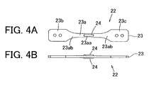
- Fig. 4 (A) is a front view of a strain amount detecting unit of the load detecting system.
- Fig. 4(B) is a base view of the strain amount detecting unit.
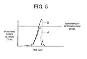
- Fig. 5 is a graph representing an example of waveforms of calibration detection values.
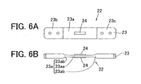
- Fig. 6(A) is a front view of another strain amount detecting unit.
- Fig. 6 (B) is a base view of the other strain amount detecting unit.
- Fig. 7 (A) is a front view of yet another strain amount detecting unit.
- Fig. 7 (B) is a base view of the other strain amount detecting unit.
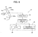
- Fig. 8 is a partial side view of a press machine according to another embodiment of the present invention, accompanied with a block diagram of a load detecting system.
- a press machine is a punch press.
- Fig. 1(A) is an entire side view
- Fig. 2 is an entire plan view
- Fig. 3 is a perspective view of a frame.
- the punch press includes a frame 1 having a C shape in side view. More specifically, the frame 1 includes a lower horizontal frame 1a extending horizontally along the floor, an upper horizontal frame 1b that is arranged above the lower horizontal frame 1a and extends in the same direction as the lower horizontal frame 1a, and a vertical frame 1c arranged to vertically connect one end of the lower horizontal frame 1a and one end of the upper horizontal frame 1b.
- the upper horizontal frame 1b is in a cantilever state, and space is provided below the upper horizontal frame 1b, where later-described turrets 2 and 3 are arranged.
- a lower portion on a base side of the upper horizontal frame 1b includes a slanted portion 1ba where a lower end lowers towards the vertical frame 1c.
- An upper portion on a base side of the lower horizontal frame 1a includes a slanted portion 1aa where an upper end rises towards the vertical frame 1c.
- Each of the upper horizontal frame 1b and the vertical frame 1c has a rectangular shape in cross section and has a plane surface on each side.
- the upper horizontal frame 1b and the lower horizontal frame 1a of the frame 1 respectively support the upper turret 2 and the lower turret 3, which are an upper tool supporting body and a lower tool supporting body, such that the turrets 2 and 3 can rotate around a coaxial vertical axis.
- a plurality of punch tools 4 and a plurality of die tools 5 are aligned in a peripheral direction on the turrets 2 and 3, respectively.
- the upper and lower turrets 2 and 3 are rotated in synchronization with each other by a motor (not illustrated) and indexed at a punching position P.
- the punch tool 4 is driven to be elevated and lowered by a ram 7.
- the ram 7 is driven to be elevated and lowered by a press drive mechanism 8 provided to the upper horizontal frame 1b.
- the press drive mechanism 8 is formed of, for example, a servomotor 9 and a movement converting mechanism 10 that converts the rotation of the servomotor 9 into linear movement.
- a plate material W is fed back and forth from side to side on a table 14 by plate material feeding means 13 so that a portion to be processed is indexed at the punching position P.
- a carriage 15 arranged to move back and forth (in a Y direction) is provided with a cross slide 16 arranged to move laterally (in an X direction), and a work holder 17 arranged to grip and hold an end of the plate material W is attached to the cross slide 16.
- a back-and-forth movement mechanism 18 arranged to move the carriage 15 back and forth is formed of, for example, a servomotor 18a and a conversion mechanism 18b such as a ball screw or the like arranged to convert the rotation of the servomotor 18a into linear movement.
- a lateral movement mechanism 19 arranged to move the cross slide 16 laterally is formed of, for example, a servomotor 19a and a conversion mechanism 19b such as a ball screw or the like arranged to convert the rotation of the servomotor 19a into linear movement.
- the punch press includes a load detecting system 21 arranged to detect load acted on the frame 1.
- the load detecting system 21 includes a strain amount detecting unit 22 illustrated in Fig. 4 .
- the strain amount detecting unit 22 includes a strain generation member 23, which is an elongate member arranged across from the upper horizontal frame 1b to the vertical frame 1c obliquely to the vertical direction, and a strain amount detecting body 24 such as a strain gauge or the like arranged to detect a strain amount of the strain generation member 23.
- the strain generation member 23 is a plate member made of metal such as a steel plate etc., and includes a narrowed portion 23aa at an intermediate portion 23a.
- the narrowed portion 23aa has a width that is narrower than those of both end portions 23b and 23c.
- the narrowed portion 23aa has a rectangular shape of a prescribed width, and since the narrowed portion 23aa has a narrow width, a cross-sectional shape thereof is smaller than those of both end portions 23b and 23c.
- the intermediate portion 23a includes the narrowed portion 23aa and cross-section changed portions 23ab on both ends, where the width gradually narrows from the corresponding end portion 23b or 23c.
- the strain generation member 23 is fixed by bolts 25 or the like such that the end portions 23b and 23c are laterally contacted to the side surface of the upper horizontal frame 1b and the vertical frame 1c. More specifically, the strain generation member 23 is arranged across from the slanted portion 1ba of the upper horizontal frame 1b to the vicinity of a front end at the vertical center of the vertical frame 1c. That is, the strain generation member 23 is disposed in the vicinity of a connection portion of the upper horizontal frame 1b and the vertical frame 1c.
- the strain amount detecting body 24 is attached to the intermediate portion 23a of the strain generation member 23 using glue or the like. In the present embodiment, the strain amount detecting body 24 is attached on each surface of the strain generation member 23. That is, two strain amount detecting bodies 24 are provided in the present embodiment.
- strain When load is applied to the frame 1, strain is generated at the strain generation member 23.
- the strain is converted into an electric signal by the strain amount detecting bodies 24, a bridge circuit 26, and a dynamic strain amplifier 27.
- the electric signal may be either a current signal or a voltage signal.
- the electric signal is calibrated based on well-known punching working.
- Fig. 5 illustrates the electric signal of the punching working, that is, waveforms of a punching force.
- the electric signal of the punching working is transmitted to a Numerical Control unit (NC unit) 29 and abnormality determining means 30 of a control panel 28.
- NC unit Numerical Control unit
- the NC unit 29 controls the entire machine.
- the abnormality determining means 30 compares a detection value, which is the punching force, with a set value defined as an abnormality determination level, and when the detection value exceeds the set value, the abnormality determining means 30 outputs an abnormality signal.
- a detection value which is the punching force
- a set value defined as an abnormality determination level
- the abnormality determining means 30 outputs an abnormality signal.
- a maximum detection value falls below the set value, and accordingly, the abnormality signal is not output.
- line B a maximum detection value exceeds the set value, and accordingly, the abnormality signal is output.
- an alarm is given through a lamp or a buzzer etc., or an urgent stop command is output to the NC unit 29.
- the narrowed portion 23aa having a cross-sectional area reduced in size by narrowing the width of the intermediate portion 23a of the strain generation member 23, a great amount of strain appears at the narrowed portion 23aa. Since the strain amount of the narrowed portion 23aa is detected by the strain amount detecting bodies 24, a high accuracy of the strain amount detection can be achieved, and the load can be precisely acquired.
- the abnormality determining means 30 When it is determined by the abnormality determining means 30 that the acquired load exceeds the set value, the abnormality signal is output, and the alarm is given or the urgent stop command is output to the NC unit 29. Thus, machine damage can be prevented by stopping the operation of the punch press. Further, acquired load data is stored in the NC unit 29 along with processing conditions of the time and accumulated as a database. By using the database, processing know-how can be improved.
- the strain generation member 23 is formed of a plate member, it can be easily manufactured. Moreover, since both end portions 23b and 23c of the strain generation member 23 are laterally contacted to the plane side surface of the upper horizontal frame 1b and the vertical frame 1c, the strain generation member 23 can be easily fixed to the upper horizontal frame 1b and the vertical frame 1c.
- the connection portion of the upper horizontal frame 1b and the vertical frame 1c, where the strain generation member 23 is provided, is disposed away from the press drive mechanism 8 in the horizontal direction and above the table 14. Therefore, the strain generation member 23 can be arranged without disrupting the pressing operation of the press drive mechanism 8 and the work feeding.
- connection portion of the upper horizontal frame 1b and the vertical frame 1c is the most likely portion where the upper horizontal frame 1b and the vertical frame 1c tend to deform when the pressing load is applied. Therefore, by arranging the strain generation member 23 across from the upper horizontal frame 1b to the vertical frame 1c, the load acted on the frame 1 can be reliably and accurately detected.
- the width of the intermediate portion 23a of the strain generation member 23 is narrowed, however, the shape of the strain generation member 23 may be changed as the strain amount detecting unit 22 of Fig. 6 , that is, the width of the strain generation member 23 may be constant, the intermediate portion 23a may include the thin narrowed portion 23aa, and the strain amount detecting body 24 may be attached to the thin narrowed portion 23aa.
- the narrowed portion 23aa has a rectangular shape of constant thickness, and by reducing the thickness, the cross-sectional shape of the narrowed portion 23aa is smaller than those of the end portions 23b and 23c.
- the intermediate portion 23a includes the narrowed portion 23aa and cross-section changed portions 23ab on both ends, where the width gradually narrows from the corresponding end portion 23b or 23c. In this case, when compared with other portions, the intermediate portion 23a also has a smaller cross-sectional area. Accordingly, the strain of the strain generation member 23 can be accurately detected by the strain amount detecting bodies 24.
- strain amount detecting bodies 24 on both sides of the strain generation member 23 detect the expansion and contraction in the longitudinal direction of the strain generation member 23, however, as illustrated in Fig. 7 , strain amount detecting bodies 24A and 24B may be attached on both sides in the shape of a cross so that the strain amount detecting body 24A detects expansion and contraction in the longitudinal direction of the strain generation member 23 and the other strain amount detecting body 24B detects expansion and contraction in the width direction of the strain generation member 23.
- the strain generation member 23 may be attached on each side (on right and left sides) of the frame 1, and the strain amount detecting bodies 24 may be connected to the bridge circuit 26 to acquire the electric signal.
- the strain generation member 23 may be attached on each side (on right and left sides) of the frame 1, and the strain amount detecting bodies 24 may be connected to the bridge circuit 26 to acquire the electric signal.
- a subtle load difference between the right and left sides of the frame 1 is averaged, which thereby can further improve the accuracy.
- the elongate member 23 including, at the intermediate portion, the narrowed portion 23aa having the cross-sectional area that is smaller than those of the end portions, however, the narrowed portion 23aa may not be necessarily provided.
- an elongate member 23A formed of a simple rectangular plate illustrated in Fig. 8 may be provided in place of the strain generation member 23.
- the elongate member 23A is fixed via the bolts 25 or the like such that the strain amount detecting body 24 is attached to an intermediate portion 23Aa, and that both end portions 23Ab and 23Ac are laterally contacted to the side surface of the upper horizontal frame 1b and the vertical frame 1c.
- the strain cannot be increased by the narrowed portion 23aa, however, the strain amount of the frame 1 can also be detected in good condition.
- the other configurations and advantages of the embodiment of Fig. 8 are similar to those of the first embodiment of Fig. 1 .
- the punch press is used as the press machine, however, the present invention may be applied to press machines other than the punch press, such as, for example, conventional forming machines or the like.
Landscapes
- Engineering & Computer Science (AREA)
- Mechanical Engineering (AREA)
- Control Of Presses (AREA)
- Force Measurement Appropriate To Specific Purposes (AREA)
- Bending Of Plates, Rods, And Pipes (AREA)
- Presses And Accessory Devices Thereof (AREA)
Applications Claiming Priority (2)
| Application Number | Priority Date | Filing Date | Title |
|---|---|---|---|
| JP2008297875 | 2008-11-21 | ||
| JP2009003322A JP5428342B2 (ja) | 2008-11-21 | 2009-01-09 | プレス機械 |
Publications (3)
| Publication Number | Publication Date |
|---|---|
| EP2189275A2 true EP2189275A2 (fr) | 2010-05-26 |
| EP2189275A3 EP2189275A3 (fr) | 2013-02-20 |
| EP2189275B1 EP2189275B1 (fr) | 2015-04-22 |
Family
ID=41491547
Family Applications (1)
| Application Number | Title | Priority Date | Filing Date |
|---|---|---|---|
| EP20090014057 Not-in-force EP2189275B1 (fr) | 2008-11-21 | 2009-11-10 | Presse |
Country Status (5)
| Country | Link |
|---|---|
| US (1) | US8096236B2 (fr) |
| EP (1) | EP2189275B1 (fr) |
| JP (1) | JP5428342B2 (fr) |
| CN (1) | CN101733971A (fr) |
| TW (1) | TWI469833B (fr) |
Cited By (1)
| Publication number | Priority date | Publication date | Assignee | Title |
|---|---|---|---|---|
| EP3112040A4 (fr) * | 2014-02-25 | 2017-11-29 | Amada Holdings Co., Ltd. | Presse-plieuse |
Families Citing this family (4)
| Publication number | Priority date | Publication date | Assignee | Title |
|---|---|---|---|---|
| WO2008140122A1 (fr) * | 2007-05-09 | 2008-11-20 | Nippon Steel Corporation | Dispositif et procédé de moulage par compression de plaque mince |
| US9341289B1 (en) * | 2013-03-15 | 2016-05-17 | Plastic Tubing Industries, Inc. | Corrugated drainage pipe with protuberances |
| DK179165B9 (en) * | 2016-12-01 | 2018-04-09 | Elastisense Aps | Press-working apparatus and related method |
| JP7041528B2 (ja) * | 2018-01-17 | 2022-03-24 | 株式会社ジャノメ | プレス装置、荷重補正方法およびプログラム |
Citations (4)
| Publication number | Priority date | Publication date | Assignee | Title |
|---|---|---|---|---|
| EP0448504A1 (fr) | 1990-03-20 | 1991-09-25 | Amir Shlomo | Dispositif pour exécution de procédés du travail en pièces d'oeuvre, particulièrement pour bornes de fils électriques |
| JPH04351300A (ja) | 1991-05-28 | 1992-12-07 | Murata Mach Ltd | プレス機械 |
| US5813263A (en) | 1993-10-15 | 1998-09-29 | Komatsu, Ltd. | Ram position setting method and ram control unit for press brake |
| JP2001137954A (ja) | 1999-11-18 | 2001-05-22 | Amada Co Ltd | 折曲げ加工方法および折曲げ機 |
Family Cites Families (18)
| Publication number | Priority date | Publication date | Assignee | Title |
|---|---|---|---|---|
| FR1328022A (fr) * | 1962-05-30 | 1963-05-24 | Niagara Machine & Tool Works | Appareil pour déterminer l'effort de pointe supporté par une machine, détecté par une jauge de traction |
| GB1181941A (en) * | 1968-02-08 | 1970-02-18 | Norton Tool Company Ltd | Presses |
| US4059991A (en) * | 1975-08-01 | 1977-11-29 | Dybel William P | Modular constructed load sensing system |
| JPS5442081A (en) * | 1977-09-09 | 1979-04-03 | Sumitomo Metal Ind Ltd | Load mesuring method of mechanical press |
| JPS6240938A (ja) * | 1985-08-16 | 1987-02-21 | Sumitomo Bakelite Co Ltd | 積層板の打抜特性測定装置 |
| CH667532A5 (fr) * | 1986-02-13 | 1988-10-14 | Bobst Sa | Dispositif pour mesurer la force de decoupage et limiter les surcharges dans une presse a platines. |
| IT1224044B (it) * | 1988-12-29 | 1990-09-26 | Prima Ind Spa | Pressa piegatrice di precisione per pezzi di lamiera lunghi |
| JP2569126Y2 (ja) * | 1991-01-11 | 1998-04-22 | 株式会社アマダ | プレスブレーキ |
| JPH0557605U (ja) * | 1992-01-08 | 1993-07-30 | アンリツ株式会社 | 歪センサ組立体 |
| JPH0819900A (ja) * | 1994-07-01 | 1996-01-23 | Murata Mach Ltd | プレス機械の荷重検出・対処装置 |
| JPH11123475A (ja) | 1997-10-21 | 1999-05-11 | Amada Co Ltd | タレットパンチプレス |
| US6068463A (en) * | 1998-04-01 | 2000-05-30 | Engel Maschinebau Gesellschaft M.B.H. | Injection molding machine |
| AT411164B (de) * | 2000-08-16 | 2003-10-27 | Trumpf Maschinen Austria Gmbh | Verfahren zum betrieb einer biegepresse und biegepresse, insbesondere abkantpresse |
| JP3675710B2 (ja) * | 2000-10-27 | 2005-07-27 | 矢崎総業株式会社 | センシング素子の固定構造 |
| JP2004098125A (ja) * | 2002-09-10 | 2004-04-02 | Komatsu Sanki Kk | プレス成形方法およびプレス成形装置 |
| FR2847835B1 (fr) * | 2002-11-29 | 2005-09-09 | Rbh | Dispositif de correction automatique des parametres de pliage inherents a la tole, sur une presse-plieuse |
| JP2007292159A (ja) * | 2006-04-24 | 2007-11-08 | Ntn Corp | センサ付車輪用軸受 |
| WO2009084539A1 (fr) * | 2007-12-27 | 2009-07-09 | Alps Electric Co., Ltd. | Capteur de charge |
-
2009
- 2009-01-09 JP JP2009003322A patent/JP5428342B2/ja not_active Expired - Fee Related
- 2009-11-10 EP EP20090014057 patent/EP2189275B1/fr not_active Not-in-force
- 2009-11-12 US US12/616,979 patent/US8096236B2/en not_active Expired - Fee Related
- 2009-11-19 CN CN200910222840A patent/CN101733971A/zh active Pending
- 2009-11-20 TW TW98139619A patent/TWI469833B/zh not_active IP Right Cessation
Patent Citations (4)
| Publication number | Priority date | Publication date | Assignee | Title |
|---|---|---|---|---|
| EP0448504A1 (fr) | 1990-03-20 | 1991-09-25 | Amir Shlomo | Dispositif pour exécution de procédés du travail en pièces d'oeuvre, particulièrement pour bornes de fils électriques |
| JPH04351300A (ja) | 1991-05-28 | 1992-12-07 | Murata Mach Ltd | プレス機械 |
| US5813263A (en) | 1993-10-15 | 1998-09-29 | Komatsu, Ltd. | Ram position setting method and ram control unit for press brake |
| JP2001137954A (ja) | 1999-11-18 | 2001-05-22 | Amada Co Ltd | 折曲げ加工方法および折曲げ機 |
Cited By (1)
| Publication number | Priority date | Publication date | Assignee | Title |
|---|---|---|---|---|
| EP3112040A4 (fr) * | 2014-02-25 | 2017-11-29 | Amada Holdings Co., Ltd. | Presse-plieuse |
Also Published As
| Publication number | Publication date |
|---|---|
| TWI469833B (zh) | 2015-01-21 |
| US20100126361A1 (en) | 2010-05-27 |
| JP5428342B2 (ja) | 2014-02-26 |
| US8096236B2 (en) | 2012-01-17 |
| EP2189275B1 (fr) | 2015-04-22 |
| EP2189275A3 (fr) | 2013-02-20 |
| CN101733971A (zh) | 2010-06-16 |
| TW201029764A (en) | 2010-08-16 |
| JP2010149178A (ja) | 2010-07-08 |
Similar Documents
| Publication | Publication Date | Title |
|---|---|---|
| JP6803161B2 (ja) | 金型の異常予測システム、それを備えたプレス機及び金型の異常予測方法 | |
| US8096236B2 (en) | Press machine | |
| JPH0819900A (ja) | プレス機械の荷重検出・対処装置 | |
| US5535498A (en) | Hole probe method | |
| CN107530996B (zh) | 冲压系统以及冲压系统的控制方法 | |
| JP2019537515A (ja) | 曲げ機械を駆動する方法 | |
| CN113523074B (zh) | 冲裁装置 | |
| JP6660032B2 (ja) | プレス成形荷重の測定装置および方法 | |
| JP2024155441A (ja) | プレス機の金型損傷予測方法及びその装置 | |
| US6796155B2 (en) | Sheet thickness detecting method and device therefor in bending machine, reference inter-blade distance detecting method and device therefor, and bending method and bending device | |
| JP5482413B2 (ja) | プレス機械 | |
| KR102559051B1 (ko) | 프레스 금형 평행도 측정 방법 및 장치와 프레스 장치 모니터링 방법 | |
| JP2001520121A (ja) | 少なくとも1つのクラウニングシステムと相互作用する上部桟及び下部桟の偏向検出装置を備えたプレス曲げ装置。 | |
| JPH05212455A (ja) | プレス金型の寿命検出方法および装置 | |
| CN113290125B (zh) | 一种冲裁模具行程限位装置 | |
| DE102004060413B4 (de) | Verfahren und Vorrichtung zum Überwachen der Position eines Umformwerkzeugs an seinem Träger | |
| JP2009095877A (ja) | 薄板のプレス成形装置及び方法 | |
| EP2828827B1 (fr) | Système et procédé de mesure de pièces à usiner pendant le forgeage par traitement d'image | |
| JP2013066930A (ja) | パンチプレスのブラシテーブルブラシ摩耗検出方法及び装置 | |
| CN214522139U (zh) | 一种多向调整自动冲压装置 | |
| US20030070516A1 (en) | Slug float detecting device and detection method thereof | |
| CN110666016A (zh) | 冲压床多点应变检测系统 | |
| JPH09136116A (ja) | 曲げ加工機における板厚検出方法およびその装置並びに曲げ加工方法および曲げ加工機 | |
| CN112895551A (zh) | 一种多向调整自动冲压装置 | |
| JP2018062000A (ja) | 金型の異常予測システム、それを備えたプレス機及び金型の異常予測方法 |
Legal Events
| Date | Code | Title | Description |
|---|---|---|---|
| PUAI | Public reference made under article 153(3) epc to a published international application that has entered the european phase |
Free format text: ORIGINAL CODE: 0009012 |
|
| AK | Designated contracting states |
Kind code of ref document: A2 Designated state(s): AT BE BG CH CY CZ DE DK EE ES FI FR GB GR HR HU IE IS IT LI LT LU LV MC MK MT NL NO PL PT RO SE SI SK SM TR |
|
| AX | Request for extension of the european patent |
Extension state: AL BA RS |
|
| PUAL | Search report despatched |
Free format text: ORIGINAL CODE: 0009013 |
|
| AK | Designated contracting states |
Kind code of ref document: A3 Designated state(s): AT BE BG CH CY CZ DE DK EE ES FI FR GB GR HR HU IE IS IT LI LT LU LV MC MK MT NL NO PL PT RO SE SI SK SM TR |
|
| AX | Request for extension of the european patent |
Extension state: AL BA RS |
|
| RIC1 | Information provided on ipc code assigned before grant |
Ipc: B30B 15/04 20060101AFI20130116BHEP |
|
| 17P | Request for examination filed |
Effective date: 20130809 |
|
| RBV | Designated contracting states (corrected) |
Designated state(s): AT BE BG CH CY CZ DE DK EE ES FI FR GB GR HR HU IE IS IT LI LT LU LV MC MK MT NL NO PL PT RO SE SI SK SM TR |
|
| 17Q | First examination report despatched |
Effective date: 20131004 |
|
| GRAP | Despatch of communication of intention to grant a patent |
Free format text: ORIGINAL CODE: EPIDOSNIGR1 |
|
| INTG | Intention to grant announced |
Effective date: 20141113 |
|
| GRAS | Grant fee paid |
Free format text: ORIGINAL CODE: EPIDOSNIGR3 |
|
| GRAA | (expected) grant |
Free format text: ORIGINAL CODE: 0009210 |
|
| AK | Designated contracting states |
Kind code of ref document: B1 Designated state(s): AT BE BG CH CY CZ DE DK EE ES FI FR GB GR HR HU IE IS IT LI LT LU LV MC MK MT NL NO PL PT RO SE SI SK SM TR |
|
| REG | Reference to a national code |
Ref country code: GB Ref legal event code: FG4D |
|
| REG | Reference to a national code |
Ref country code: CH Ref legal event code: EP |
|
| REG | Reference to a national code |
Ref country code: AT Ref legal event code: REF Ref document number: 722950 Country of ref document: AT Kind code of ref document: T Effective date: 20150515 |
|
| REG | Reference to a national code |
Ref country code: IE Ref legal event code: FG4D |
|
| REG | Reference to a national code |
Ref country code: DE Ref legal event code: R096 Ref document number: 602009030748 Country of ref document: DE Effective date: 20150603 |
|
| REG | Reference to a national code |
Ref country code: NL Ref legal event code: VDEP Effective date: 20150422 |
|
| REG | Reference to a national code |
Ref country code: AT Ref legal event code: MK05 Ref document number: 722950 Country of ref document: AT Kind code of ref document: T Effective date: 20150422 |
|
| REG | Reference to a national code |
Ref country code: LT Ref legal event code: MG4D |
|
| PG25 | Lapsed in a contracting state [announced via postgrant information from national office to epo] |
Ref country code: NL Free format text: LAPSE BECAUSE OF FAILURE TO SUBMIT A TRANSLATION OF THE DESCRIPTION OR TO PAY THE FEE WITHIN THE PRESCRIBED TIME-LIMIT Effective date: 20150422 |
|
| PG25 | Lapsed in a contracting state [announced via postgrant information from national office to epo] |
Ref country code: HR Free format text: LAPSE BECAUSE OF FAILURE TO SUBMIT A TRANSLATION OF THE DESCRIPTION OR TO PAY THE FEE WITHIN THE PRESCRIBED TIME-LIMIT Effective date: 20150422 Ref country code: FI Free format text: LAPSE BECAUSE OF FAILURE TO SUBMIT A TRANSLATION OF THE DESCRIPTION OR TO PAY THE FEE WITHIN THE PRESCRIBED TIME-LIMIT Effective date: 20150422 Ref country code: NO Free format text: LAPSE BECAUSE OF FAILURE TO SUBMIT A TRANSLATION OF THE DESCRIPTION OR TO PAY THE FEE WITHIN THE PRESCRIBED TIME-LIMIT Effective date: 20150722 Ref country code: ES Free format text: LAPSE BECAUSE OF FAILURE TO SUBMIT A TRANSLATION OF THE DESCRIPTION OR TO PAY THE FEE WITHIN THE PRESCRIBED TIME-LIMIT Effective date: 20150422 Ref country code: LT Free format text: LAPSE BECAUSE OF FAILURE TO SUBMIT A TRANSLATION OF THE DESCRIPTION OR TO PAY THE FEE WITHIN THE PRESCRIBED TIME-LIMIT Effective date: 20150422 Ref country code: PT Free format text: LAPSE BECAUSE OF FAILURE TO SUBMIT A TRANSLATION OF THE DESCRIPTION OR TO PAY THE FEE WITHIN THE PRESCRIBED TIME-LIMIT Effective date: 20150824 |
|
| PG25 | Lapsed in a contracting state [announced via postgrant information from national office to epo] |
Ref country code: GR Free format text: LAPSE BECAUSE OF FAILURE TO SUBMIT A TRANSLATION OF THE DESCRIPTION OR TO PAY THE FEE WITHIN THE PRESCRIBED TIME-LIMIT Effective date: 20150723 Ref country code: LV Free format text: LAPSE BECAUSE OF FAILURE TO SUBMIT A TRANSLATION OF THE DESCRIPTION OR TO PAY THE FEE WITHIN THE PRESCRIBED TIME-LIMIT Effective date: 20150422 Ref country code: AT Free format text: LAPSE BECAUSE OF FAILURE TO SUBMIT A TRANSLATION OF THE DESCRIPTION OR TO PAY THE FEE WITHIN THE PRESCRIBED TIME-LIMIT Effective date: 20150422 Ref country code: IS Free format text: LAPSE BECAUSE OF FAILURE TO SUBMIT A TRANSLATION OF THE DESCRIPTION OR TO PAY THE FEE WITHIN THE PRESCRIBED TIME-LIMIT Effective date: 20150822 |
|
| REG | Reference to a national code |
Ref country code: DE Ref legal event code: R097 Ref document number: 602009030748 Country of ref document: DE |
|
| PG25 | Lapsed in a contracting state [announced via postgrant information from national office to epo] |
Ref country code: EE Free format text: LAPSE BECAUSE OF FAILURE TO SUBMIT A TRANSLATION OF THE DESCRIPTION OR TO PAY THE FEE WITHIN THE PRESCRIBED TIME-LIMIT Effective date: 20150422 Ref country code: DK Free format text: LAPSE BECAUSE OF FAILURE TO SUBMIT A TRANSLATION OF THE DESCRIPTION OR TO PAY THE FEE WITHIN THE PRESCRIBED TIME-LIMIT Effective date: 20150422 |
|
| PLBE | No opposition filed within time limit |
Free format text: ORIGINAL CODE: 0009261 |
|
| STAA | Information on the status of an ep patent application or granted ep patent |
Free format text: STATUS: NO OPPOSITION FILED WITHIN TIME LIMIT |
|
| PG25 | Lapsed in a contracting state [announced via postgrant information from national office to epo] |
Ref country code: CZ Free format text: LAPSE BECAUSE OF FAILURE TO SUBMIT A TRANSLATION OF THE DESCRIPTION OR TO PAY THE FEE WITHIN THE PRESCRIBED TIME-LIMIT Effective date: 20150422 Ref country code: PL Free format text: LAPSE BECAUSE OF FAILURE TO SUBMIT A TRANSLATION OF THE DESCRIPTION OR TO PAY THE FEE WITHIN THE PRESCRIBED TIME-LIMIT Effective date: 20150422 Ref country code: SK Free format text: LAPSE BECAUSE OF FAILURE TO SUBMIT A TRANSLATION OF THE DESCRIPTION OR TO PAY THE FEE WITHIN THE PRESCRIBED TIME-LIMIT Effective date: 20150422 Ref country code: RO Free format text: LAPSE BECAUSE OF NON-PAYMENT OF DUE FEES Effective date: 20150422 |
|
| 26N | No opposition filed |
Effective date: 20160125 |
|
| PG25 | Lapsed in a contracting state [announced via postgrant information from national office to epo] |
Ref country code: SI Free format text: LAPSE BECAUSE OF FAILURE TO SUBMIT A TRANSLATION OF THE DESCRIPTION OR TO PAY THE FEE WITHIN THE PRESCRIBED TIME-LIMIT Effective date: 20150422 |
|
| PG25 | Lapsed in a contracting state [announced via postgrant information from national office to epo] |
Ref country code: MC Free format text: LAPSE BECAUSE OF FAILURE TO SUBMIT A TRANSLATION OF THE DESCRIPTION OR TO PAY THE FEE WITHIN THE PRESCRIBED TIME-LIMIT Effective date: 20150422 Ref country code: LU Free format text: LAPSE BECAUSE OF FAILURE TO SUBMIT A TRANSLATION OF THE DESCRIPTION OR TO PAY THE FEE WITHIN THE PRESCRIBED TIME-LIMIT Effective date: 20151110 |
|
| REG | Reference to a national code |
Ref country code: CH Ref legal event code: PL |
|
| GBPC | Gb: european patent ceased through non-payment of renewal fee |
Effective date: 20151110 |
|
| PG25 | Lapsed in a contracting state [announced via postgrant information from national office to epo] |
Ref country code: CH Free format text: LAPSE BECAUSE OF NON-PAYMENT OF DUE FEES Effective date: 20151130 Ref country code: LI Free format text: LAPSE BECAUSE OF NON-PAYMENT OF DUE FEES Effective date: 20151130 |
|
| REG | Reference to a national code |
Ref country code: IE Ref legal event code: MM4A |
|
| REG | Reference to a national code |
Ref country code: FR Ref legal event code: ST Effective date: 20160729 |
|
| PG25 | Lapsed in a contracting state [announced via postgrant information from national office to epo] |
Ref country code: BE Free format text: LAPSE BECAUSE OF FAILURE TO SUBMIT A TRANSLATION OF THE DESCRIPTION OR TO PAY THE FEE WITHIN THE PRESCRIBED TIME-LIMIT Effective date: 20150422 |
|
| PG25 | Lapsed in a contracting state [announced via postgrant information from national office to epo] |
Ref country code: IE Free format text: LAPSE BECAUSE OF NON-PAYMENT OF DUE FEES Effective date: 20151110 Ref country code: GB Free format text: LAPSE BECAUSE OF NON-PAYMENT OF DUE FEES Effective date: 20151110 |
|
| PG25 | Lapsed in a contracting state [announced via postgrant information from national office to epo] |
Ref country code: FR Free format text: LAPSE BECAUSE OF NON-PAYMENT OF DUE FEES Effective date: 20151130 |
|
| PG25 | Lapsed in a contracting state [announced via postgrant information from national office to epo] |
Ref country code: SM Free format text: LAPSE BECAUSE OF FAILURE TO SUBMIT A TRANSLATION OF THE DESCRIPTION OR TO PAY THE FEE WITHIN THE PRESCRIBED TIME-LIMIT Effective date: 20150422 Ref country code: BG Free format text: LAPSE BECAUSE OF FAILURE TO SUBMIT A TRANSLATION OF THE DESCRIPTION OR TO PAY THE FEE WITHIN THE PRESCRIBED TIME-LIMIT Effective date: 20150422 Ref country code: HU Free format text: LAPSE BECAUSE OF FAILURE TO SUBMIT A TRANSLATION OF THE DESCRIPTION OR TO PAY THE FEE WITHIN THE PRESCRIBED TIME-LIMIT; INVALID AB INITIO Effective date: 20091110 |
|
| PG25 | Lapsed in a contracting state [announced via postgrant information from national office to epo] |
Ref country code: SE Free format text: LAPSE BECAUSE OF FAILURE TO SUBMIT A TRANSLATION OF THE DESCRIPTION OR TO PAY THE FEE WITHIN THE PRESCRIBED TIME-LIMIT Effective date: 20150422 Ref country code: CY Free format text: LAPSE BECAUSE OF FAILURE TO SUBMIT A TRANSLATION OF THE DESCRIPTION OR TO PAY THE FEE WITHIN THE PRESCRIBED TIME-LIMIT Effective date: 20150422 |
|
| PG25 | Lapsed in a contracting state [announced via postgrant information from national office to epo] |
Ref country code: TR Free format text: LAPSE BECAUSE OF FAILURE TO SUBMIT A TRANSLATION OF THE DESCRIPTION OR TO PAY THE FEE WITHIN THE PRESCRIBED TIME-LIMIT Effective date: 20150422 Ref country code: MT Free format text: LAPSE BECAUSE OF FAILURE TO SUBMIT A TRANSLATION OF THE DESCRIPTION OR TO PAY THE FEE WITHIN THE PRESCRIBED TIME-LIMIT Effective date: 20150422 |
|
| PGFP | Annual fee paid to national office [announced via postgrant information from national office to epo] |
Ref country code: IT Payment date: 20171124 Year of fee payment: 9 |
|
| PG25 | Lapsed in a contracting state [announced via postgrant information from national office to epo] |
Ref country code: MK Free format text: LAPSE BECAUSE OF FAILURE TO SUBMIT A TRANSLATION OF THE DESCRIPTION OR TO PAY THE FEE WITHIN THE PRESCRIBED TIME-LIMIT Effective date: 20150422 |
|
| PGFP | Annual fee paid to national office [announced via postgrant information from national office to epo] |
Ref country code: DE Payment date: 20181120 Year of fee payment: 10 |
|
| PG25 | Lapsed in a contracting state [announced via postgrant information from national office to epo] |
Ref country code: IT Free format text: LAPSE BECAUSE OF NON-PAYMENT OF DUE FEES Effective date: 20181110 |
|
| REG | Reference to a national code |
Ref country code: DE Ref legal event code: R119 Ref document number: 602009030748 Country of ref document: DE |
|
| PG25 | Lapsed in a contracting state [announced via postgrant information from national office to epo] |
Ref country code: DE Free format text: LAPSE BECAUSE OF NON-PAYMENT OF DUE FEES Effective date: 20200603 |