EP2189308A1 - Arbeitsfahrzeug - Google Patents
Arbeitsfahrzeug Download PDFInfo
- Publication number
- EP2189308A1 EP2189308A1 EP08765104A EP08765104A EP2189308A1 EP 2189308 A1 EP2189308 A1 EP 2189308A1 EP 08765104 A EP08765104 A EP 08765104A EP 08765104 A EP08765104 A EP 08765104A EP 2189308 A1 EP2189308 A1 EP 2189308A1
- Authority
- EP
- European Patent Office
- Prior art keywords
- vehicle
- shaft
- front wheel
- front wheels
- gear
- Prior art date
- Legal status (The legal status is an assumption and is not a legal conclusion. Google has not performed a legal analysis and makes no representation as to the accuracy of the status listed.)
- Withdrawn
Links
Images






Classifications
-
- B—PERFORMING OPERATIONS; TRANSPORTING
- B62—LAND VEHICLES FOR TRAVELLING OTHERWISE THAN ON RAILS
- B62D—MOTOR VEHICLES; TRAILERS
- B62D7/00—Steering linkage; Stub axles or their mountings
- B62D7/18—Steering knuckles; King pins
-
- B—PERFORMING OPERATIONS; TRANSPORTING
- B60—VEHICLES IN GENERAL
- B60G—VEHICLE SUSPENSION ARRANGEMENTS
- B60G3/00—Resilient suspensions for a single wheel
- B60G3/18—Resilient suspensions for a single wheel with two or more pivoted arms, e.g. parallelogram
- B60G3/20—Resilient suspensions for a single wheel with two or more pivoted arms, e.g. parallelogram all arms being rigid
-
- B—PERFORMING OPERATIONS; TRANSPORTING
- B60—VEHICLES IN GENERAL
- B60K—ARRANGEMENT OR MOUNTING OF PROPULSION UNITS OR OF TRANSMISSIONS IN VEHICLES; ARRANGEMENT OR MOUNTING OF PLURAL DIVERSE PRIME-MOVERS IN VEHICLES; AUXILIARY DRIVES FOR VEHICLES; INSTRUMENTATION OR DASHBOARDS FOR VEHICLES; ARRANGEMENTS IN CONNECTION WITH COOLING, AIR INTAKE, GAS EXHAUST OR FUEL SUPPLY OF PROPULSION UNITS IN VEHICLES
- B60K17/00—Arrangement or mounting of transmissions in vehicles
-
- B—PERFORMING OPERATIONS; TRANSPORTING
- B60—VEHICLES IN GENERAL
- B60G—VEHICLE SUSPENSION ARRANGEMENTS
- B60G2200/00—Indexing codes relating to suspension types
- B60G2200/40—Indexing codes relating to the wheels in the suspensions
- B60G2200/422—Driving wheels or live axles
-
- B—PERFORMING OPERATIONS; TRANSPORTING
- B60—VEHICLES IN GENERAL
- B60G—VEHICLE SUSPENSION ARRANGEMENTS
- B60G2204/00—Indexing codes related to suspensions per se or to auxiliary parts
- B60G2204/10—Mounting of suspension elements
- B60G2204/14—Mounting of suspension arms
- B60G2204/148—Mounting of suspension arms on the unsprung part of the vehicle, e.g. wheel knuckle or rigid axle
-
- B—PERFORMING OPERATIONS; TRANSPORTING
- B60—VEHICLES IN GENERAL
- B60G—VEHICLE SUSPENSION ARRANGEMENTS
- B60G2204/00—Indexing codes related to suspensions per se or to auxiliary parts
- B60G2204/40—Auxiliary suspension parts; Adjustment of suspensions
- B60G2204/416—Ball or spherical joints
-
- B—PERFORMING OPERATIONS; TRANSPORTING
- B60—VEHICLES IN GENERAL
- B60G—VEHICLE SUSPENSION ARRANGEMENTS
- B60G2300/00—Indexing codes relating to the type of vehicle
- B60G2300/08—Agricultural vehicles
- B60G2300/082—Tractors
-
- F—MECHANICAL ENGINEERING; LIGHTING; HEATING; WEAPONS; BLASTING
- F16—ENGINEERING ELEMENTS AND UNITS; GENERAL MEASURES FOR PRODUCING AND MAINTAINING EFFECTIVE FUNCTIONING OF MACHINES OR INSTALLATIONS; THERMAL INSULATION IN GENERAL
- F16H—GEARING
- F16H3/00—Toothed gearings for conveying rotary motion with variable gear ratio or for reversing rotary motion
- F16H3/02—Toothed gearings for conveying rotary motion with variable gear ratio or for reversing rotary motion without gears having orbital motion
- F16H3/08—Toothed gearings for conveying rotary motion with variable gear ratio or for reversing rotary motion without gears having orbital motion exclusively or essentially with continuously meshing gears, that can be disengaged from their shafts
- F16H3/087—Toothed gearings for conveying rotary motion with variable gear ratio or for reversing rotary motion without gears having orbital motion exclusively or essentially with continuously meshing gears, that can be disengaged from their shafts characterised by the disposition of the gears
- F16H3/093—Toothed gearings for conveying rotary motion with variable gear ratio or for reversing rotary motion without gears having orbital motion exclusively or essentially with continuously meshing gears, that can be disengaged from their shafts characterised by the disposition of the gears with two or more countershafts
Definitions
- the present invention relates to a work vehicle which is provided with a front wheel being rotated by a front wheel drive shaft which is protrusively mounted from the inside of a front axle case in the front part of the vehicle to the right and the left and interposed the universal shaft couplings respectively adjacent to the outer side and the inner side of the vehicle, and the upper and lower suspension arms, which are located respectively between this front wheel and the front axle case and support so as to enable the front wheels mounted at the upper side and at the lower side of said front wheel drive shaft to swing in the vertical direction of the vehicle, and in more detail, relates to a work vehicle provided with the front wheels which are capable of steering and can be separately swung in the vertical direction of the vehicle.
- a wheel-type tractor (Patent Document 1) wherein power to front wheels is transmitted to a differential gear in a front axle case through a transmission shaft to a front wheel drive output shaft protruded from the front part of a mission case, and the front wheels are driven by the differential gear through a front drive shaft, and at the same time, a double wishbone type front suspension supporting the front wheels rotatably in the vertical direction of the vehicle through spherical joints located at the ends of the upper and the lower arms mounted pivotally on the right and left sides of the front axle case are so provided that the front wheels can be swung in the vertical direction of the vehicle, and also another wheel tractor (Patent Document 2) is cited, wherein the double wishbone type front suspension is provided and the front drive shaft is capable of responding to a large working angle of a steering wheel by providing universal shaft couplings in the middle part of the right and left front wheel drive shafts respectively.
- a front suspension for a wheel-type tractor causes also the same problem as described above and further had problems that the construction is complicated and the workability such as maintenance work is reduced because a supporting member supporting an intermediate shaft located between universal shaft couplings respectively provided on the right and left portions of a front wheel drive shaft, has to be provided separately in a small space. Therefore, it is an object of the present invention to provide a work vehicle, wherein the front wheels are so provided that those front wheels are capable of steering and can be swung separately in the vertical direction of the vehicle, and the front suspension construction is made simple and travelling performance and workability are improved.
- the invention according to claim 1 in a work vehicle provided with the front wheels being rotated by front wheel drive shafts which are protrusively mounted from the inside of a front axle case in the front part of the vehicle to the right and the left and interposed the universal shaft couplings respectively adjacent to the outer side and the inner side of the vehicle, and the upper and lower suspension arms, which are located respectively between the front wheel and the front axle case and support so as to enable the front wheels mounted at the upper side and at the lower side of the front wheel drive shaft to swing in the vertical direction of the vehicle, characterized in that, the front wheel drive shaft is connected with sun gears disposed at the center of the front wheels; the front wheels are rotated by rotating a ring gear disposed on the outer periphery of planetary gears through a plural of planetary gears disposed on the outer periphery of the sun gears; as well as stays provided at the upper end and the lower ends of a steering knuckle of the front wheel are connected respectively with the outer ends of the upper and lower suspension arms through
- the present invention according to claim 2 is characterized in that, in the work vehicle according to claim 1, the universal shaft coupling provided adjacent to the outer side of the vehicle is comprised of a bent member with a supporting part built in.
- the present invention according to claim 3 is characterized in that, in the work vehicle according to claim 1, the spherical joint is detachably provided.
- a work vehicle provided with front wheels being rotated by front wheel drive shafts which are protrusively mounted to the right and the left from the inside of a front axle case in the front part of the vehicle and interposed universal shaft couplings respectively adjacent to the outer side and the inner side of the vehicle, and the upper and lower suspension arms, which are located respectively between the front wheel and the front axle case, and are mounted at the upper side and at the lower side of the front wheel drive shaft, support the front wheels so as to enable the front wheels to swing in the vertical direction of the vehicle, because the front wheel drive shaft is connected with sun gears disposed at the center of the front wheel, the front wheel is rotated by rotating a ring gear disposed on the outer periphery of a plural of planetary gears through the planetary gears disposed on the outer periphery of the sun gears, and stays provided at the upper end and the lower ends of a steering knuckle of the front wheel are connected respectively with the outer ends of the upper and lower suspension arms through sp
- a universal shaft coupling provided adjacent to the outer side of a vehicle is comprised of a bent member with a supporting part stored inside, it is possible to support a front wheel drive shaft provided between universal shaft couplings provided adjacent to the outer side and the inner side of the vehicle, by the supporting part in the bent member, without supporting by a complicated construction using a different member in a small space, and front suspension construction can be compact and also work including its assembly and maintenance can be performed easily. Accordingly, it is possible to provide a work vehicle with enhanced workability.
- Fig. 1 is a side view of a wheel type tractor as one example of the present invention
- Fig. 2 shows a plan view of the same tractor.
- a tractor 21 of this example front wheels 23 and rear wheels 24 are provided in front and at the back of a vehicle frame 22, a bonnet 25 is formed above the front wheel 23, an engine 40 as a motor is disposed inside it, a clutch housing 41 is disposed at the back of the engine 40, further a mission case 42 is disposed at the back of this clutch housing 41, and power from the engine 40 is transmitted to the front wheels 23 and the rear wheels 24.
- a cabin 27 (ROPS specification is also acceptable) is provided in series at the back of the bonnet 25. It should be noted that, the direction used in the description including back/front, right/left, and upper/lower is indicated as based on the travelling direction of a vehicle.
- an engine key, a gas pedal, a clutch pedal, an operation pedal such as the clutch pedal 28, a steering wheel 29, a driver' s seat 30 and the like are provided as a vehicle handling part.
- a wind shield 31, a rear window 32, a door 33, a roof 34 and the like may be respectively provided.
- up/down steps 37 for an operator to get on and off the cabin 27 are fixedly mounted on a vehicle frame 22 at the lower part of the cabin 27.
- the power from the engine 40 is transmitted to a PTO shaft, not shown, protruded from the rear end of the mission case 42, this PTO shaft drives a working machinery, not shown, mounted at the vehicle rear end, through a universal joint, a working machinery mounting device 39 and the like, which are not shown.
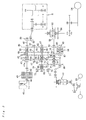
- Fig. 3 is a skeleton drawing of a power transmission system
- Fig. 4 is a cross-sectional development view of the inside of a mission case.
- a multiple disc type main clutch 43 is housed in the clutch housing 41, which is coordinated with the clutch pedal 28.
- rotation of an output shaft 44 of the engine 40 is input to the main clutch 43, an output shaft 45 of the main clutch 43 is protruded toward the vehicle rear part and provided at the same shaft center with that of a PTO clutch shaft 46.
- a power transmission gear 47 and a PTO third-speed click 47a are disposed at the rear end of an output shaft 45 and a PTO first-speed gear 48, a PTO second-speed gear 49 and a PTO reverse gear 50 are respectively loosely fit on the PTO clutch shaft 46.
- a PTO first-speed gear 48, a PTO second-speed gear 49 and the power transmission gear 47 are respectively engaged with transmission gears 52, 53 and 54 mounted on a main shaft 51, the PTO reverse gear 50 is engaged with a transmission gear 56 through a counter gear 55, and rotation driving force is transmitted by sliding of PTO clutch sliders 57 and 58 to a PTO shaft 60 from the transmission gears 52, 53 and 56, and the PTO third-speed click 47a through a PTO clutch shaft 46 and a speed reduction gear 59, and the working machinery s is driven.
- Transmission gears 52, 53, 54 and 56 fixedly mounted on the main shaft 51 are respectively engaged with a main speed-change first gear 62, a main speed-change second gear 63, a main speed-change third gear 64, a main speed-change fourth gear 65, which are loosely fit on a main speed-change shaft 61.
- Two main speed-change clutch sliders 66 and 67 which are spline-fitted so as to allow sliding in the axial direction of this main speed-change shaft 61, are coordinated with a main speed-change lever, not shown, provided in the cabin 27.
- a positive rotation side gear 68 and a reverse rotation side gear 69 are respectively loosely fit on the same shaft center.
- a reversal lever not shown, provided in the cabin 27, a reversal clutch 70 is selected and connected either in the forward movement side or the backward movement side, the rotation of the main speed-change shaft 61 is transmitted to either the positive rotation side gear 68 or the reverse rotation side gear 69.
- the rotation is transmitted to neither the positive rotation side gear 68 nor a reverse rotation side gear 69.
- the positive rotation side gear 68 and the reverse rotation side gear 69 are engaged respectively with a gear 72 fitted on a transmission shaft 71 and a counter gear 74 fitted on a counter shaft 73, and this counter gear 74 is engaged with a gear 75 fitted on the transmission shaft 71.
- the gear 72 fitted on the transmission shaft 71 is engaged with the positive rotation side gear 68, and is engaged, as well, with a gear 77 mounted on the same shaft center line with that of an auxiliary speed-change shaft 76 and at the front part in the vehicle movement direction. Since an auxiliary speed-change shifter 78 is fitted on the auxiliary speed-change shaft 76, it is enabled to slide freely between the front part of the auxiliary speed-change shaft 76 and the rear part of the gear 77.
- This auxiliary speed-change shifter 78 is operated by an auxiliary speed-change lever, not shown, provided in the cabin 27, and an auxiliary speed-change device is so constructed that it is possible to switch over to any one of a state of auxiliary speed-change third speed (auxiliary speed-change high-speed stage), wherein a auxiliary speed-change shifter teeth 78a formed at the front part of the auxiliary speed-change shifter 78 is positioned at the rear position 77a of the gear 77, a state of auxiliary speed-change second speed, wherein the auxiliary speed-change shifter teeth 78a is engaged with teeth 77b mounted at the rear end of the gear 77, a state of auxiliary speed-change first speed, wherein teeth 78b formed at the center upper part of the auxiliary speed-change shifter 78 is engaged with a gear 79 mounted adjacent to the center of the transmission shaft 71, a (neutral) state, wherein the rotation power is not transmitted to the auxiliary speed-change shifter 78, and a state of auxiliary speed
- a rear wheel differential device 83 is disposed at the rear part of a mission case 42, and rotation of the auxiliary speed-change shaft 76 is input to the rear wheel differential device 83 through the gear 82 formed at the rear end of this auxiliary speed-change shaft 76, and rear wheels 24 are driven through a wheel shaft 18 and the like.
- reference numeral 84 is a brake device.
- gears 80 or 81 mounted on the auxiliary speed-change shaft 76 rotation power being input from a standard drive input gear 86 loosely fit on a front wheel output shaft 85, or an acceleration drive input gear 87, to the front wheel output shaft 85 through 4 wheel drive-front wheel acceleration drive switch system 88, is input to a front wheel side differential device 97 through a front wheel transmission shaft 89 connected with the front end of this front wheel output shaft 85, and front wheels 23 are driven through a front wheel drive shaft 101 protruded in the right and the left directions from a front axle case 19 fixedly mounted on a side frame, not shown, in which the differential device 97 is mounted. It should be noted that, though the description above is explained about a 4 wheel drive tractor 21, a front drive work vehicle is also acceptable.
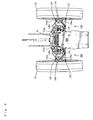
- Fig. 5 is a front elevation view showing a suspension between the right and left front wheels.
- Fig. 6 is a plan view showing a suspension between the right and left front wheels.
- Fig. 7 is an enlarged perspective view looking at a suspension of the right front wheel from its bottom.
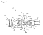
- Fig. 8 is a front elevation schematic view showing the periphery of a suspension of the left front wheel.
- Fig. 9 is a front elevation perspective view showing the inner construction of a bent member in an enlarged manner.
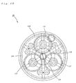
- Fig. 10 is a side-elevation schematic view showing the construction in a supporting case.
- Double wishbone type suspensions 100 provided at the front wheels 23 are mounted, as shown in Figs. 5 to 7 , symmetrically from the front axle case 19 provided adjacent to the center of a vehicle, to the right and left front wheels 23. And, suspension arms 105a and 105b (double wishbone) having an approximate U-shape (not limited) in planar view, shown in Fig.
- a reference numeral 99 (not shown in Figs. 6 and 7 ) shown in Fig. 5 is a hydraulic cylinder functioning as an elastic body of a suspension 100.
- the front wheel drive shaft 101 protruded to the right and left directions from the front axle case 19, is first connected, as shown in Fig. 8 , with the inner end of a universal shaft coupling 108 which is located on the extension line of the front wheel drive shaft 101, and mounted adjacent to the inner side of a vehicle, and rotates universally so as to enable to transmit the direction of power transmission of the front wheel drive shaft 101 to the upper and lower directions of a vehicle, and an intermediate shaft 109 is connected with the outer end of this universal shaft coupling 108.
- the intermediate shaft 109 is connected with the inner end of a bent member 110 being a universal shaft coupling 110, which is located on the extension line of the intermediate shaft 109, and mounted adjacent to the outer side of a vehicle, and rotates universally so as to enable to transmit the direction of power transmission of the intermediate shaft 109 to the right and left directions of a vehicle, and a transmission shaft 111 is connected with the outer end of the bent member 110.
- the front wheel drive shaft 101 is constructed by the front wheel drive shaft 101 sandwiching the universal shaft couplings 108 and 110, the intermediate shaft 109 and the transmission shaft 111.
- a supporting part 114 is mounted between an arm 112 which is located adjacent to the centre of the inside and is coordinated with the intermediate shaft 109, and an arm 113 which is coordinated with the transmission shaft 111.
- the ends of stays 114b and 114c are attached, through an elastic member 115 being composed of rubber, plastic and the like (not specifically limited, but any material which prevents metallic contact is acceptable) attached to the arms 112 and 113, to the upper and lower positions of a cylinder part 114a ( if the inside is cylindrical, then outside shape is not limited) which is mounted so as to cover the outer periphery of shafts 112 and 113, and has a cylindrical hollow inside, and the other ends of these stays 114b and the 114c are fixedly mounted at the upper end and the lower end adjacent to the center in a case c of the bent member 110.
- a sun gear 116 shown in Fig. 10 is fixedly set up at the center part of a supporting case 103 of the right and left front wheels 23, and planetary gears 117 are fixedly set up at the outside periphery of this sun gear 116, so as to engage with the sun gear 116, and further a ring gear 118 is fixedly set up at the outside periphery of the planetary gears 117 so as to engage with the planetary gears 117. And, the outer end of the transmission shaft 111 is connected with the sun gear 116.
- the front wheels 23 may be driven by the rotation of this transmission shaft 111 through the supporting case and the like, by directly attaching by fitting, the transmission shaft 111 on the inner center part of the supporting case provided inside the front wheel 23.
- the direction of transmission of the driving force is changed so that a part between the right/left front wheel drive shaft 101 and the intermediate shaft 109 is bent in the upward direction or the downward direction respectively at the right and left universal shaft couplings 108, and the power is transmitted from the front wheel shaft 101 to the intermediate shaft 109 by a conventional method.
- a link member 119 such as a rod coordinated with the steering handle wheel 29 shown in Figs. 6 and 7 , is connected with a steering knuckle 104 of the right and left front wheels 23, and by sliding (which is well known, therefore the detailed explanation is omitted) the link member 119 with turning operation of the steering wheel 29, the right and left front wheels 23 are rotated in the right and left directions.
- each of the right and left intermediate shafts 109 and the inner part of the transmission shaft 111 transmit the power in the right direction or the left direction from the intermediate shaft 109 to the transmission shaft 111 in a conventional method, respectively by the right and left bent members 110 provided between the intermediate shaft 109 and the transmission shaft 111, the direction of transmission can be changed. It should be noted that, following a maximum turning angle 55 degree of the right and left front wheels 23 by the steering wheel 29, the bending angle between the intermediate shaft 109 and the transmission shaft 111 is allowed up to 55 degree by the bent member 110.
- the front wheel drive shaft 101 is supported by the front wheel transmission shaft 89, the differential device 97 and the like
- the transmission shaft 111 is supported by the sun gears 116, the supporting case 103 and the like
- the intermediate shaft 109 by sandwiching the arm 112 coordinated with the outer end by the supporting part 14 being housed in the bent member 110, between the arms 113 coordinated with the transmission shaft 111, the intermediate shaft 109 is supported by the supporting part 114 .
- the suspension 100 can be a simple construction and it is possible to enhance the workability of assembling and maintenance.
- this king pin angle easily by which it is possible to adjust the extent of stability of steering operation, resilience to the state of travelling in a straight line, and absorbing shocks from a road because the inclination angle (king pin angle) to the vertical direction in the vicinity of a fixedly-mounting part 103a of the supporting case 103 in the stays 104a and 104b, is changed by changing the tightening extent of the attaching member 107b at the fixing part 107a, and the workability can be enhanced.
- suspension arms 105a and 105b of the present invention are excellent in strength and design of the suspension arms 105a and 105b because of a crescent shape with an approximate U-shape in planar view, and more resistant to breakage compared with a conventional suspension arm, and condition confirmation and maintenance of the front wheel drive shaft 101, the intermediate shaft 109, the universal shaft joint 108 and the like, can be done easily from a space of a concave part adjacent to the center in planar view, workability can be enhanced
- the driving force from the engine 40 can be effectively transmitted to the front wheels 23 by directly connecting the front wheel drive shaft 101 with the front wheels 23 through the intermediate shaft 109 and the transmission shaft 111, and each of gears 117 and 118 is sequentially rotated by rotating the sun gear 116 and the weighty front wheels 23 of a vehicle can be driven more effectively.
- a planetary carrier 119 supporting these planetary gears 117 is fixed on the supporting case 103, and the planetary gears 117 are supported by the planetary carrier 119 and the supporting case 103, it is not necessary to differently mount a supporting member for supporting the planetary gears 117 and the planetary gears 117 are securely supported, and the rotation of the planetary gears 117 can be kept stable.
- a wheel type tractor (a farm working vehicle) as one example of a work vehicle
- the present invention is not limited thereto and can be applied to a semi-crawler type tractor provided with the right and left front wheels, a rice planting machine, a power tiller and the like as a farm working vehicle, a tractor shovel, a motor grader, a scraper, a trencher and the like as a construction work vehicle and every type of a work vehicle provided with suspensions at the right and left front wheels.
Landscapes
- Engineering & Computer Science (AREA)
- Mechanical Engineering (AREA)
- Chemical & Material Sciences (AREA)
- Combustion & Propulsion (AREA)
- Transportation (AREA)
- Arrangement And Driving Of Transmission Devices (AREA)
- Steering-Linkage Mechanisms And Four-Wheel Steering (AREA)
- Vehicle Body Suspensions (AREA)
Applications Claiming Priority (2)
| Application Number | Priority Date | Filing Date | Title |
|---|---|---|---|
| JP2007236472A JP2009067176A (ja) | 2007-09-12 | 2007-09-12 | 作業車両 |
| PCT/JP2008/060291 WO2009034754A1 (ja) | 2007-09-12 | 2008-06-04 | 作業車両 |
Publications (2)
| Publication Number | Publication Date |
|---|---|
| EP2189308A1 true EP2189308A1 (de) | 2010-05-26 |
| EP2189308A4 EP2189308A4 (de) | 2012-04-04 |
Family
ID=40451766
Family Applications (1)
| Application Number | Title | Priority Date | Filing Date |
|---|---|---|---|
| EP08765104A Withdrawn EP2189308A4 (de) | 2007-09-12 | 2008-06-04 | Arbeitsfahrzeug |
Country Status (4)
| Country | Link |
|---|---|
| US (1) | US20100200323A1 (de) |
| EP (1) | EP2189308A4 (de) |
| JP (1) | JP2009067176A (de) |
| WO (1) | WO2009034754A1 (de) |
Cited By (1)
| Publication number | Priority date | Publication date | Assignee | Title |
|---|---|---|---|---|
| WO2019090055A1 (en) * | 2017-11-02 | 2019-05-09 | Clark Equipment Company | Loader suspension |
Families Citing this family (4)
| Publication number | Priority date | Publication date | Assignee | Title |
|---|---|---|---|---|
| CN103963637B (zh) * | 2014-04-29 | 2017-08-25 | 浙江吉利控股集团有限公司 | 一种用于车辆的整体式转向驱动桥和电动车辆 |
| CN107414893B (zh) * | 2017-09-05 | 2023-09-19 | 深圳市腾隆达智能科技有限公司 | 一种重载两轮差动机器人的通用底盘 |
| US20200284323A1 (en) | 2019-03-06 | 2020-09-10 | Deere & Company | Powershift transmission for agricultural machines |
| US12370885B1 (en) * | 2024-05-06 | 2025-07-29 | Schaeffler Technologies AG & Co. KG | Planetary inner knuckle |
Family Cites Families (34)
| Publication number | Priority date | Publication date | Assignee | Title |
|---|---|---|---|---|
| US2801702A (en) * | 1953-05-06 | 1957-08-06 | Gen Motors Corp | Steerable driving axle |
| US2871966A (en) * | 1956-12-26 | 1959-02-03 | Clark Equipment Co | Steering drive axle |
| US3243007A (en) * | 1961-05-09 | 1966-03-29 | Koehring Co | Wheel suspension for driven steerable wheels |
| NL286392A (de) * | 1961-12-07 | |||
| DE1980530U (de) * | 1967-08-16 | 1968-03-07 | Kempf Geb | Doppelgelenk fuer lenkbare angetriebene schwingachsen, bei dem um das doppelgelenk ein kardankreuz angeordnet ist. |
| US3969950A (en) * | 1974-03-04 | 1976-07-20 | Trw Inc. | Drive assembly |
| DE2922660C2 (de) * | 1979-06-02 | 1985-04-04 | Zahnradfabrik Friedrichshafen Ag, 7990 Friedrichshafen | Getriebene Lenkachse |
| DE2930298C2 (de) * | 1979-07-26 | 1983-11-17 | Zahnradfabrik Friedrichshafen Ag, 7990 Friedrichshafen | Angetriebene Lenkachse |
| US4282949A (en) * | 1979-10-29 | 1981-08-11 | General Motors Corporation | Hub locks for independently suspended wheels |
| US4736821A (en) * | 1981-10-02 | 1988-04-12 | Rockwell International Corporation | Fluid cooled friction brake |
| US4722540A (en) * | 1984-11-13 | 1988-02-02 | The Budd Company | Steering knuckle assembly |
| DE3514146A1 (de) * | 1985-04-19 | 1986-10-23 | Daimler-Benz Ag, 7000 Stuttgart | Angetriebene achse fuer nutzfahrzeuge |
| JPS61199423U (de) * | 1985-06-03 | 1986-12-13 | ||
| US4693699A (en) * | 1985-09-24 | 1987-09-15 | Deere & Company | Seal assembly for rotary and reciprocating motion |
| JPH0249148Y2 (de) * | 1986-06-16 | 1990-12-25 | ||
| JPH0629541Y2 (ja) * | 1986-07-19 | 1994-08-10 | セイレイ工業株式会社 | 動力伝達構造 |
| US5087229A (en) * | 1991-05-06 | 1992-02-11 | General Motors Corporation | Independently suspended steerable motor wheel apparatus |
| JP3367614B2 (ja) * | 1991-10-17 | 2003-01-14 | 株式会社小松製作所 | ダンプトラックの操舵輪油圧駆動装置 |
| JP2632641B2 (ja) * | 1994-03-11 | 1997-07-23 | 株式会社中村自工 | ユニバーサルジョイントの首垂れ防止装置 |
| JP3473331B2 (ja) * | 1997-06-27 | 2003-12-02 | 日本精工株式会社 | ダブルカルダン式等速ジョイント |
| ITPD980138A1 (it) * | 1998-05-29 | 1999-11-29 | Carraro Spa | Assale motore sterzante |
| JP4212693B2 (ja) * | 1998-12-02 | 2009-01-21 | 松井ワルターシャイド株式会社 | 駆動軸 |
| US6471224B1 (en) * | 1999-12-21 | 2002-10-29 | Dana Corporation | Kingpin independent front suspension |
| US6470991B1 (en) | 2000-09-14 | 2002-10-29 | Deere & Company | Tractor with front suspension |
| JP3440082B2 (ja) * | 2001-02-19 | 2003-08-25 | 科学技術振興事業団 | 電気自動車用インホイールモーター |
| DE10120432A1 (de) * | 2001-04-26 | 2002-11-14 | Walterscheid Gmbh Gkn | Zentriertes Doppelkreuzgelenk |
| JP3969088B2 (ja) * | 2001-12-21 | 2007-08-29 | 株式会社ジェイテクト | 等速ジョイント |
| WO2003059720A1 (en) * | 2002-01-15 | 2003-07-24 | Terratronics Pty Ltd | Vehicle with integrated control of steering and wheel speed |
| EP1356962A1 (de) * | 2002-04-24 | 2003-10-29 | CNH Italia S.p.A. | Gefederte, angetriebene Vorderachse für Fahrzeuge |
| US7766353B2 (en) * | 2003-10-03 | 2010-08-03 | Gpv, Llc | Wheel unit for automotive vehicles |
| US7264079B2 (en) * | 2004-08-05 | 2007-09-04 | Cnh America Llc | Steerable rear tractor suspension |
| JP2007015619A (ja) * | 2005-07-08 | 2007-01-25 | Honda Motor Co Ltd | 車両の車輪懸架装置 |
| JP2007161022A (ja) * | 2005-12-12 | 2007-06-28 | Bridgestone Corp | インホイールモータシステム |
| US7537536B2 (en) * | 2006-06-13 | 2009-05-26 | Hvolka Dusan J | Two speed gearbox |
-
2007
- 2007-09-12 JP JP2007236472A patent/JP2009067176A/ja active Pending
-
2008
- 2008-06-04 WO PCT/JP2008/060291 patent/WO2009034754A1/ja not_active Ceased
- 2008-06-04 EP EP08765104A patent/EP2189308A4/de not_active Withdrawn
- 2008-06-04 US US12/677,687 patent/US20100200323A1/en not_active Abandoned
Cited By (2)
| Publication number | Priority date | Publication date | Assignee | Title |
|---|---|---|---|---|
| WO2019090055A1 (en) * | 2017-11-02 | 2019-05-09 | Clark Equipment Company | Loader suspension |
| US11052715B2 (en) | 2017-11-02 | 2021-07-06 | Clark Equipment Company | Loader suspension |
Also Published As
| Publication number | Publication date |
|---|---|
| US20100200323A1 (en) | 2010-08-12 |
| JP2009067176A (ja) | 2009-04-02 |
| WO2009034754A1 (ja) | 2009-03-19 |
| EP2189308A4 (de) | 2012-04-04 |
Similar Documents
| Publication | Publication Date | Title |
|---|---|---|
| EP1327549B1 (de) | Traktor | |
| US20120046138A1 (en) | Power Train for Work Vehicle | |
| US10737721B2 (en) | Steerable drive axle for a tracked work vehicle | |
| EP1745972B1 (de) | Zugmaschine | |
| US20100200323A1 (en) | Work vehicle | |
| KR101029371B1 (ko) | 트랙터 | |
| US7836982B2 (en) | Compact crawler type tractor | |
| JP2008179233A (ja) | クローラ式作業車両 | |
| KR101195206B1 (ko) | 트랙터 | |
| JP2537139B2 (ja) | 乗用型農機に於ける車輪操向装置 | |
| JP4570119B2 (ja) | トラクタ | |
| JP6132756B2 (ja) | 作業車 | |
| JP2002002525A (ja) | 走行車両のステアリング装置 | |
| CN120986537A (zh) | 一种基于双流差速转向的拖拉机四轮360度转向系统 | |
| CN203528590U (zh) | 作业车辆 | |
| JP4869836B2 (ja) | クローラ式作業車両 | |
| JP2009067177A (ja) | 作業車両 | |
| JP4672886B2 (ja) | トラクタ | |
| JP2006103634A (ja) | 作業車両 | |
| KR20060022661A (ko) | 트랙터 | |
| JP2005132211A (ja) | 走行作業機における作業機への動力伝達装置 | |
| JPS63235128A (ja) | 農用トラクタの前輪用差動装置 | |
| JP2002120579A (ja) | トラクタ | |
| JPH0752667A (ja) | 作業機の2駆・4駆切換構造 | |
| JP2005212612A (ja) | トラクタ |
Legal Events
| Date | Code | Title | Description |
|---|---|---|---|
| PUAI | Public reference made under article 153(3) epc to a published international application that has entered the european phase |
Free format text: ORIGINAL CODE: 0009012 |
|
| 17P | Request for examination filed |
Effective date: 20100312 |
|
| AK | Designated contracting states |
Kind code of ref document: A1 Designated state(s): AT BE BG CH CY CZ DE DK EE ES FI FR GB GR HR HU IE IS IT LI LT LU LV MC MT NL NO PL PT RO SE SI SK TR |
|
| AX | Request for extension of the european patent |
Extension state: AL BA MK RS |
|
| DAX | Request for extension of the european patent (deleted) | ||
| A4 | Supplementary search report drawn up and despatched |
Effective date: 20120301 |
|
| RIC1 | Information provided on ipc code assigned before grant |
Ipc: B60K 17/00 20060101ALN20120224BHEP Ipc: B62D 7/18 20060101ALI20120224BHEP Ipc: B60G 7/02 20060101ALI20120224BHEP Ipc: B60B 35/14 20060101ALI20120224BHEP Ipc: B60G 3/20 20060101AFI20120224BHEP |
|
| 17Q | First examination report despatched |
Effective date: 20121106 |
|
| 18D | Application deemed to be withdrawn |
Effective date: 20130319 |