EP2189340A2 - Module de caméra doté de fonctions multiples - Google Patents
Module de caméra doté de fonctions multiples Download PDFInfo
- Publication number
- EP2189340A2 EP2189340A2 EP09171441A EP09171441A EP2189340A2 EP 2189340 A2 EP2189340 A2 EP 2189340A2 EP 09171441 A EP09171441 A EP 09171441A EP 09171441 A EP09171441 A EP 09171441A EP 2189340 A2 EP2189340 A2 EP 2189340A2
- Authority
- EP
- European Patent Office
- Prior art keywords
- sensor
- light
- optical
- camera module
- camera
- Prior art date
- Legal status (The legal status is an assumption and is not a legal conclusion. Google has not performed a legal analysis and makes no representation as to the accuracy of the status listed.)
- Ceased
Links
- 230000003287 optical effect Effects 0.000 claims abstract description 155
- 238000003384 imaging method Methods 0.000 claims abstract description 98
- 230000008878 coupling Effects 0.000 claims abstract description 29
- 238000010168 coupling process Methods 0.000 claims abstract description 29
- 238000005859 coupling reaction Methods 0.000 claims abstract description 29
- 238000000034 method Methods 0.000 claims abstract description 20
- 239000013307 optical fiber Substances 0.000 claims abstract description 10
- 238000012544 monitoring process Methods 0.000 claims abstract description 4
- 238000005286 illumination Methods 0.000 claims description 20
- 230000002123 temporal effect Effects 0.000 claims description 7
- 230000007613 environmental effect Effects 0.000 claims description 4
- 238000010304 firing Methods 0.000 claims description 3
- 238000012634 optical imaging Methods 0.000 claims description 3
- 239000000835 fiber Substances 0.000 abstract description 3
- 238000001514 detection method Methods 0.000 description 15
- 230000005540 biological transmission Effects 0.000 description 13
- 238000013461 design Methods 0.000 description 9
- 239000011248 coating agent Substances 0.000 description 8
- 238000000576 coating method Methods 0.000 description 8
- 230000005855 radiation Effects 0.000 description 8
- 238000007788 roughening Methods 0.000 description 8
- 238000000926 separation method Methods 0.000 description 7
- 230000008901 benefit Effects 0.000 description 5
- 230000008859 change Effects 0.000 description 5
- 230000001629 suppression Effects 0.000 description 4
- 230000009977 dual effect Effects 0.000 description 3
- 230000000694 effects Effects 0.000 description 3
- 239000000463 material Substances 0.000 description 3
- 238000005259 measurement Methods 0.000 description 3
- 238000012545 processing Methods 0.000 description 3
- 230000001360 synchronised effect Effects 0.000 description 3
- 238000009833 condensation Methods 0.000 description 2
- 230000005494 condensation Effects 0.000 description 2
- 238000010276 construction Methods 0.000 description 2
- 238000011156 evaluation Methods 0.000 description 2
- 230000004907 flux Effects 0.000 description 2
- 239000011521 glass Substances 0.000 description 2
- 230000010354 integration Effects 0.000 description 2
- 238000013507 mapping Methods 0.000 description 2
- 239000003595 mist Substances 0.000 description 2
- 239000002245 particle Substances 0.000 description 2
- 239000004033 plastic Substances 0.000 description 2
- 229920003023 plastic Polymers 0.000 description 2
- 230000003595 spectral effect Effects 0.000 description 2
- 230000006641 stabilisation Effects 0.000 description 2
- 238000011105 stabilization Methods 0.000 description 2
- 230000007704 transition Effects 0.000 description 2
- 241000533950 Leucojum Species 0.000 description 1
- 238000004378 air conditioning Methods 0.000 description 1
- 230000002238 attenuated effect Effects 0.000 description 1
- 238000005452 bending Methods 0.000 description 1
- 230000000903 blocking effect Effects 0.000 description 1
- 230000000295 complement effect Effects 0.000 description 1
- 230000003247 decreasing effect Effects 0.000 description 1
- 230000023077 detection of light stimulus Effects 0.000 description 1
- 230000004069 differentiation Effects 0.000 description 1
- 238000009826 distribution Methods 0.000 description 1
- 239000000428 dust Substances 0.000 description 1
- 239000003365 glass fiber Substances 0.000 description 1
- 238000010191 image analysis Methods 0.000 description 1
- 230000006872 improvement Effects 0.000 description 1
- 230000007246 mechanism Effects 0.000 description 1
- 238000005457 optimization Methods 0.000 description 1
- 238000001556 precipitation Methods 0.000 description 1
- 230000011514 reflex Effects 0.000 description 1
- 238000005096 rolling process Methods 0.000 description 1
- 238000012216 screening Methods 0.000 description 1
- 239000004065 semiconductor Substances 0.000 description 1
- 230000001953 sensory effect Effects 0.000 description 1
- 230000000087 stabilizing effect Effects 0.000 description 1
Images




Classifications
-
- H—ELECTRICITY
- H04—ELECTRIC COMMUNICATION TECHNIQUE
- H04N—PICTORIAL COMMUNICATION, e.g. TELEVISION
- H04N23/00—Cameras or camera modules comprising electronic image sensors; Control thereof
- H04N23/50—Constructional details
- H04N23/55—Optical parts specially adapted for electronic image sensors; Mounting thereof
-
- B—PERFORMING OPERATIONS; TRANSPORTING
- B60—VEHICLES IN GENERAL
- B60R—VEHICLES, VEHICLE FITTINGS, OR VEHICLE PARTS, NOT OTHERWISE PROVIDED FOR
- B60R2300/00—Details of viewing arrangements using cameras and displays, specially adapted for use in a vehicle
- B60R2300/10—Details of viewing arrangements using cameras and displays, specially adapted for use in a vehicle characterised by the type of camera system used
- B60R2300/108—Details of viewing arrangements using cameras and displays, specially adapted for use in a vehicle characterised by the type of camera system used using 'non-standard' camera systems, e.g. camera sensor used for additional purposes i.a. rain sensor, camera sensor split in multiple image areas
-
- B—PERFORMING OPERATIONS; TRANSPORTING
- B60—VEHICLES IN GENERAL
- B60S—SERVICING, CLEANING, REPAIRING, SUPPORTING, LIFTING, OR MANOEUVRING OF VEHICLES, NOT OTHERWISE PROVIDED FOR
- B60S1/00—Cleaning of vehicles
- B60S1/02—Cleaning windscreens, windows or optical devices
- B60S1/04—Wipers or the like, e.g. scrapers
- B60S1/06—Wipers or the like, e.g. scrapers characterised by the drive
- B60S1/08—Wipers or the like, e.g. scrapers characterised by the drive electrically driven
- B60S1/0818—Wipers or the like, e.g. scrapers characterised by the drive electrically driven including control systems responsive to external conditions, e.g. by detection of moisture, dirt or the like
- B60S1/0822—Wipers or the like, e.g. scrapers characterised by the drive electrically driven including control systems responsive to external conditions, e.g. by detection of moisture, dirt or the like characterized by the arrangement or type of detection means
- B60S1/0833—Optical rain sensor
- B60S1/0844—Optical rain sensor including a camera
Definitions
- the invention is based on known camera modules, which are already used today for a variety of applications in the automotive sector.
- camera modules can be used for vehicle surroundings detection, that is to say for the observation of reception areas in the surroundings of the motor vehicle.
- the camera modules can be used in particular for use behind a windshield of a motor vehicle, in particular in the region of the interior mirror.
- the camera modules described within the scope of the present invention can also be used for other purposes in the automotive sector or in other fields.
- Cameras for vehicle environment detection increasingly demand versatile requirements. So be in DE 10 2004 015 040 A1 Cameras for motor vehicles are described in which a primary function of a traffic sensor system is present, for example for the detection of traffic signs, lane recognition, object recognition, illumination control, measurement of the intensity of the incident light from the front or similar primary functions using a camera.
- the camera described there contains secondary functions, which are based on an optical secondary sensor, which is also integrated in the camera.
- secondary functions for example, a rain sensor, a light sensor, a condensation and fog detection, Sonneneinstrahlidess- and solar radiation intensity detection (solar load detection) or other sensor functions can be realized.
- Both the primary function and the secondary sensor use the in DE 10 2004 015 040 A1 described camera the same image sensor.
- the DE 10 2004 015 040 A1 described camera has over conventional cameras for use in the automotive sector already has the advantage that it can be implemented in a particularly space-saving and cost-effective. This is particularly due to the high degree of integration, in which primary and secondary functions are integrated into one and the same module. Nevertheless, the in DE 10 2004 015 040 A1 described camera further starting points for an optimization. Thus, in various embodiments, it uses a separate concave mirror for the optical secondary sensor in order to image optical signals of this secondary sensor onto the image sensor chip. Such additional optical elements are technically complex to implement. Furthermore, the utilization of the available sensor surfaces can be further optimized.
- a camera module for use in a motor vehicle and a method for optical monitoring of an environmental region of a motor vehicle are proposed which at least largely avoid the disadvantages of the camera modules and methods known from the prior art and exploit the potential for improvement described above.
- the camera module can be similar in many parts to that in DE 10 2004 015 040 A1 be configured camera module, so that for possible optional embodiments in particular this camera module can be referenced.
- the proposed method can be carried out in particular using a camera module according to the invention in accordance with one or more of the embodiments described below. In this respect, reference may be made to the following description of the camera module for possible details of the method.
- the camera module comprises at least one camera with a spatially resolving imaging sensor, wherein the camera is set up to detect a recording area.
- the camera may comprise, for example, an imaging optical system, in particular at least one objective with at least one lens.
- the receiving area may in particular be a receiving area in the surrounding area of the motor vehicle, so that the camera module, for example, as described above, behind the windshield or a other disc of the motor vehicle can be mounted to observe a traffic space of the environment of the motor vehicle.
- the camera function of the camera module can serve one or more of the primary functions described above, such as traffic sign recognition, lane recognition, object recognition, illumination control, intensity measurement of incident light, or similar functions.
- the camera module further comprises at least one integrated in the camera module optical secondary sensor for sensing at least one secondary function.
- this secondary function may comprise, for example, one or more of the functions of a rain sensor system, a light sensor system, a condensation or fog detection, a detection of the solar irradiation direction and solar radiation intensity or similar secondary functions.
- An integration is an embodiment in which the at least one optical secondary sensor is integrated, for example, in a housing of the camera module.
- the at least one secondary sensor can be arranged wholly or partly within a scattered-light diaphragm of the camera module.
- the proposed camera module differs from known from earlier applications modules in which, for example, a rain-light sensor is used in addition to a video camera with a lens hood, so as a separate component.
- the secondary sensor has at least one optical sensor and at least one light guide.
- the optical sensor is used to detect optical signals of the secondary sensor and can be designed as a simple optical sensor, so for example as a photodiode or similar photosensitive semiconductor device.
- this optical sensor can in turn also comprise a spatially resolving optical sensor.
- this optical sensor like the camera's resolving imaging sensor, may in turn comprise a CCD chip, a CMOS chip or other types of spatially resolving imaging sensors or imaging chips include.
- a light guide is to be understood a device which is capable of transmitting optical signals in the form of electromagnetic waves in the visible and / or infrared and / or ultraviolet spectral range over a predetermined transmission path.
- the term of the light guide is to be understood in the context of the present invention.
- the light guide may be or include an element that conducts light in the classical sense.
- the optical waveguide can thus be in particular a light guide based on internal total reflection or comprise such a waveguide. In principle, however, the term also encompasses other transmission arrangements for the directional transmission of light, preferably with the suppression of scattering.
- air or vacuum could act as a transmission medium in the transmission path, wherein at least one optical element may be provided at the beginning and / or end of the transmission path, for example at least one mirror and / or at least one prism and / or at least one lens.
- at least one diaphragm for example at least one stray light diaphragm, may be provided.
- the optical waveguide may further comprise one or more walls which laterally delimit the transmission path and serve as mechanical stabilization, for example as mechanical stabilization of the scattered light diaphragm.
- the optical waveguide can thus be configured simply as an elongated scattered-light diaphragm, with at least one stray-light diaphragm at the beginning and / or end of the transmission path and mechanically stabilizing walls.
- an optical waveguide in the sense of the present invention is to be understood merely as an elongate, scatter-suppressing transmission path.
- the light guide can be made of suitable materials, for example of glass or, which is preferred in the context of the present invention, of one or more plastics. Also combinations of different materials are possible.
- the light guide should be arranged to pass the optical signal from a coupling-in area of the camera module to the optical sensor.
- the coupling region of the camera module can, for example, an opening of the Camera module towards the receiving area include, for example, an opening of a housing of the camera module, for example, towards a windshield of the motor vehicle.
- the optical fiber does not have to guide the optical signal of the optical secondary sensor on the complete path from this coupling region to the optical sensor, but only on at least a portion of this optical path.
- a light entry may also be arranged at a distance from the windscreen, and a light exit of the light guide spaced from the optical sensor.
- at least a portion of the optical path should encompass the light guide.
- the camera module can advantageously be optionally equipped in various ways.
- the camera module can include a scattered light diaphragm for reducing the introduction of scattered light into the imaging sensor or into the camera.
- the light guide can be at least partially integrated in this lens hood, so for example, form a part of this lens hood.
- the light guide can have at least one surface which suppresses light reflection, for example a roughened and / or a coated surface.
- the optical waveguide can have at least one deflecting element, that is to say an element which is set up to change a direction of the beam path through the optical waveguide.
- This deflection element which is explained in more detail below by way of examples, can be configured to tilt a viewing region of the optical secondary sensor with respect to a viewing angle of the camera, that is to say, for example, with respect to an optical axis of the camera.
- consideration of an environmental area arranged above the motor vehicle is considered in this way, so that, for example, a sensor for detecting solar radiation or ambient lighting (solar load) can be realized.
- the deflecting element may for example comprise a prism, in particular an end face of the light guide designed as a prism, a mirror, an at least partially mirrored surface of the light guide or similar deflecting elements.
- the deflecting element may be designed in one piece with the other at least one light guide, that is, for example integrated in this light guide be. Alternatively or additionally, however, this deflection element can also be connected only to the light guide, for example, be placed on this light guide.
- the optical waveguide can furthermore have at least one optical imaging property, ie a property in which an optical signal in the form of at least one original image is converted by the optical waveguide into an image.
- This optical imaging property may include, for example, a collimating property, a focusing property, a converging property, an enlarging and / or decreasing imaging property, a change in the height-to-width ratio of the image (as explained below), or similar optical properties.
- the optical waveguide in the coupling-in region can have a light entrance, which has at least one first imaging element.
- This first imaging element may comprise, for example, at least one prism, a multiprism, in particular a Fresnel lens or similar imaging elements. Combinations of such elements are possible.
- At least one second imaging element can also be provided at a light exit of the light guide, which in turn can likewise have one or more of the imaging elements just mentioned.
- the optical sensor of the secondary optical sensor may be at least partially identical to the imaging sensor of the camera.
- the recording area of the camera can be imaged as a primary image onto a primary image area of the imaging sensor and the viewing area of the optical secondary sensor as a secondary image onto a secondary image area of the imaging sensor.
- the primary image area and the secondary image area can be identical or at least partially different.
- the camera module comprises an image acquisition controller which is set up to record signals of the optical secondary sensor of signals by means of a temporal recording sequence disconnect the camera.
- the optical secondary sensor for example, a flash illumination, in particular a synchronized flash illumination, have.
- this may be flash illumination for generating a flash pattern with multiple flash firing per frame repetition time.
- the camera module may generally comprise at least one light source, which may also include, for example, the flash illumination.
- at least one coupling-in device is provided for coupling light from the light source into the light guide.
- the light of the light source can be used, for example, to illuminate the field of view of the optical secondary sensor through the light guide.
- the coupling device for example by using appropriate blocking or by a clever coupling, is configured such that light is coupled only in the direction of the coupling region, ie in the direction of the light entrance of the light guide, whereas a coupling or a Conduction of the light of the light source towards the optical sensor is at least partially suppressed or avoided.
- the optical sensor of the secondary optical sensor is at least partially identical to the imaging sensor of the camera, but also in other cases, it is particularly preferred if for the optical secondary sensor at least partially an image pickup optics of the camera is used.
- the image pickup optical system since the image pickup optical system must simultaneously have optimum imaging properties for the secondary optical sensor and the primary camera function, it is particularly preferred if the optical fiber itself has imaging properties which, in combination with the imaging properties Image capture optics, provide for optimal mapping of the optical signal to the optical sensor of the optical secondary sensor.
- a scattered light aperture which is assigned to the primary function, at the same time be shaped as a light-conducting, predominantly, for example, flat channel for collimating the light signal.
- the at least one light entry and / or the at least one light exit of the light guide may preferably contain prisms and / or imaging elements, for example prisms, which complement each other according to a lens function.
- lenses may be provided, so that the image is focused on the optical sensor or the spatially resolving imaging sensor, for example on an inner and / or outer disc surface, for example, a windshield.
- a temporal pattern of flash illumination may be coupled into the windshield, for example obliquely to the disc surface so that raindrops decouple onto the light (detection of light loss as in conventional rain sensors), or nearly perpendicular to the disc surface so that, for example, rain becomes visible as a reflex image ,
- the at least one light entry or the at least one light exit of the light guide can have, for example, multiprism structures.
- Multiprismen Modell are technically easy to implement, so that can be realized by means of this technique, for example, magnification optics or other types of image projectors.
- the proposed camera module in one or more of the above-described embodiments preferably, by one or a few relatively easily finished attachments or parts, preferably without the usual flash lighting in the rain sensor in conjunction with software, the secondary functions for both rain detection and a To realize light detection by means of an image sensor.
- an optical signal of the optical secondary sensor arranged, for example, on a part of the spatially resolving imaging sensor or another sensing element, So the optical sensor, transmitted.
- the secondary image of the optical secondary sensor generated in this way can be evaluated at least approximately, that is, if the light transmission of the camera would be focused on the outer and / or inner surface of the windshield or vehicle window.
- the proposed camera module further enables maximum utilization of the sensor surface available for the function of, for example, a rain-light sensor system, for example the spatially resolving imaging sensor.
- a rain-light sensor system for example the spatially resolving imaging sensor.
- such rain-light sensor systems generally have secondary image areas in which the width-to-height ratio is very large.
- the transition between the primary image area and the secondary image area on the spatially resolving imaging sensor should be as clearly separable as possible by subsequent image processing.
- the secondary light of the secondary optical sensor should be as possible formed when hitting the position-sensitive imaging sensor that the sensing surface of this spatially resolving imaging sensor, which receives the secondary image area, and only this, as uniformly much secondary radiation of the optical signal of the secondary optical sensor.
- this is a ratio of approximately 21.
- the observed surface of the field of view of the optical secondary sensor for example on the windshield of the motor vehicle, should, on the other hand, generally not have such a large width-to-height ratio, For example, Raindrops produce a round picture in a first approximation.
- the transmission path of the secondary light that is to say the optical signal of the optical secondary sensor
- the transmission path of the secondary light can be adjusted such that exactly and preferably only the required light with the corresponding width-to-height ratio impinges on the imaging optics of the camera and / or the spatially resolving imaging sensor ,
- preferably completely unwanted extraneous light in the propagation path of the light guide can be removed, for example by this is not forwarded and / or collimated.
- the proposed camera module as a secondary function of the optical secondary sensor, also allows realization of a detection of the light incident from above, without and / or with a differentiation of the direction (solar load sensing).
- a dipped beam can be quickly controlled automatically, and / or it can, for example, the respective side of a left-right-split air conditioning control.
- the proposed camera module can be realized in particular cost.
- the proposed camera module offers the possibility of a material cost-optimized solution in which as few and inexpensive components are used.
- the camera module in addition to the actual camera, for example, only a cleverly designed lens hood with the additional function of the light guide and possibly a few other additional components.
- the lens hood can be easily and inexpensively finished, for example, as a shed bundle of glass fibers and / or plastic fibers, for example, similar to a faceted optics.
- the beam path of the secondary light of the optical secondary sensor and the beam path of the primary light of the primary function of the camera can be clearly separated by the use of the light guide, without, for example, the position of a diaphragm and / or an object or another type of imaging optics of the camera consuming Beam path must be adjusted.
- the primary image area can also overlap with the secondary image area on the spatially resolving imaging sensor. Especially with a bright primary image and a faint secondary image, the thus weakened signal-to-noise ratio can be significantly improved.
- the above-described effect of simplifying the construction of the camera module and the realization of a cost-effective design can be achieved, for example, by using oblong and / or flat optical fibers for the optical signal of the secondary sensor in which the light entry and / or the light exit
- suitable prism structures and / or lens structures are shaped accordingly.
- surface sections of the optical waveguide for example, can be used as mirror surfaces for deflecting the optical signal, as a result of which additional deflecting elements, such as those shown in FIG DE 10 2004 015 040 A1 described parabolic mirror, preferably completely can be dispensed with.
- remaining surfaces of the light guide for example, by roughening or refractive index changes can be designed so that no total reflection of the incident light from the outside of the light can take place more, so that this light guide preferably used in a dual function as a scattered light aperture or part of a scattered light aperture for the primary light can be.
- the light guide may have a funnel-shaped course in order to achieve these properties.
- a redundancy in a measuring path for example, a rain sensor and / or a light sensor can be achieved. This redundancy can be used if too much or no light source is used from a viewing direction of the field of view.
- the imaging properties of the light guide for example, again a funnel shape of the light guide, in one direction and by a flat height extension in another direction, a bundling or collimation of the secondary light or a change achieve the height-to-width ratio.
- the collimation can, for example, already take place before an imaging optics of the camera and, for example, not already in a light source of the optical secondary sensor, so that, for example, an aperture in the image recording optics can optionally be dispensed with.
- the secondary light guide that is to say the guidance of the optical signal of the optical secondary sensor, can preferably be realized below the course of the primary light of the camera.
- the secondary image area is thus preferably arranged in the lower area of the primary radiation, which is usually darker than the upper area. This means that a higher signal dynamic is available for the detection of the secondary radiation or the secondary optical signal in the same range.
- the secondary light guide can also be done in other ways, for example, arranged laterally behind the lens hoods of the camera module. The use of multiple optical fibers instead of a single optical fiber is conceivable.
- the optical waveguide can be configured in particular at its light entrance and / or at its light exit in such a way that the pane surface is imaged sharply or at least substantially sharply on the optical sensor, for example the spatially resolving imaging sensor.
- this mapping can be done with a screening with an accuracy of at least 0.4 mm.
- the field of view of the optical secondary sensor can deviate from the viewing direction, for example the optical axis, of the camera.
- additional functions such as the detection of the incident light from above, realized with the secondary function and the optical secondary sensor.
- the optionally proposed temporally synchronized recording in particular by means of flash illumination, can also be used for optimizing the available capacities of the imaging sensor.
- the flash lighting can be configured such that a multiple Flash triggering of the flash illumination takes place per image of the spatially resolving imaging sensor. Particularly preferably, this multiple flash triggering takes place bundled in time in the time range in which the secondary image of the optical secondary sensor is recorded.
- a method for optically monitoring an environmental region of a motor vehicle is also proposed.
- a camera module is used, in particular a camera module according to one or more of the embodiments described above. Accordingly, for possible details of the proposed method, reference may be made largely to the above description.
- a receiving area is detected by means of at least one camera with a spatially resolving imaging sensor, in particular a traffic space of the surroundings of the motor vehicle.
- at least one optical secondary sensor integrated in the camera module is used, in particular a rain sensor.
- the optical secondary sensor comprises at least one optical sensor. At least one optical signal is passed from a coupling region of the camera module to the optical sensor.
- the term guiding is to be understood broadly in the context of the present invention and essentially relates to a transmission with suppression of stray light.
- a light guide and / or one or more stray light diaphragms may be used, in particular using one or more roughened and / or coated surfaces.
- an optical sensor which is at least partially identical to the position-sensitive imaging sensor of the camera can be used.
- the spatially resolving imaging sensor can be subdivided into a primary image area in which the imaging area is imaged, and a secondary image area from which the optical signal is completely or partially recorded and in which, for example, a viewing area of the optical secondary sensor is imaged.
- the primary image area and the secondary image area may, as shown above, preferably be at least partially different.
- a flash illumination of the optical secondary sensor can be used, in particular a flash illumination for generating a flash pattern with multiple flash triggering each frame repetition time.
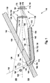
- FIG. 1 a first embodiment of a camera module 110 according to the invention is shown in a sectional view from the side, on the basis of which an embodiment of a method according to the invention is to be illustrated.
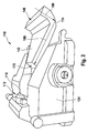
- FIG. 2 shows this embodiment in a perspective view.
- the camera module 110 corresponds in its basic structure and its operation, for example, substantially in DE 10 2004 015 040 A1 described camera module, so that reference can be made to this document with regard to possible uses and possible further embodiments.
- the camera module 110 includes a camera 112 with an in FIG. 1 only indicated imaging optics 114 with a lens 116. Furthermore, the camera 112 includes a spatially resolving imaging sensor 118, which is also referred to as an imager. This spatially resolving imaging sensor 118 may include, for example, a CCD chip and / or a CMOS chip. The camera 112 has a receiving area 120 whose boundary is in FIG. 1 symbolically represented by dashed lines. This receiving area 120 has an optical axis 122.
- the camera module 110 is in the in FIG. 1 illustrated embodiment integrated in a housing 124, which in FIG. 1 is merely indicated.
- the camera module 110 can be integrated, for example, behind a windshield 126 of a motor vehicle, for example in the region of an interior mirror of the motor vehicle, in order to detect a traffic space 128 in an environment 130 of the motor vehicle by means of the reception area 120.
- the housing 124 further includes an in which in FIG. 1 illustrated embodiment of multi-part stray light aperture 132.
- This lens hood is designed in two parts in this embodiment and has an upper lens hood 134 and a lower lens hood 136.
- an integrated optical secondary sensor 138 which, in contrast to many known from the prior art secondary sensors in the in FIG. 1 illustrated embodiment is integrated into the housing 124 of the camera module 110.
- This optical secondary sensor 138 is configured in the illustrated embodiment, for example, as a rain sensor or for other, above or below described in more detail functions.
- the optical secondary sensor comprises an optical sensor 140, which in this exemplary embodiment is configured at least partially identically to the spatially resolving imaging sensor 118, so that the secondary optical sensor 138 and the camera 112 share the spatially resolving imaging sensor 118.
- the optical secondary sensor 138 has a separate optical sensor.
- the secondary optical sensor 138 includes a light guide 142 configured to receive an optical signal in the form of secondary light (in FIG. 1 designated by the reference numeral 144) from a coupling-in area 146 of the camera module 110 to the optical sensor 140.
- the light guide 142 has a light entrance 148, which is arranged near an inner surface 150 of the windshield 126, so that by means of the optical secondary sensor 138, for example, particles 152 and / or raindrops 154 on an outer surface 156 and / or mist 158 or Hail 160 or raindrops in an environment 130 of the motor vehicle are observable.
- Other functions are described below or are, for example, the DE 10 2004 015 040 A1 removable.
- the light guide 142 is integrated in the illustrated embodiment as part of the lens hood 132 in the lower lens hood 136. Alternatively or additionally, the light guide 142 may also be arranged, for example, wholly or partially adjacent to the scattered light diaphragm 132. If the light guide 142 is used as part of the scattered light diaphragm 132, it is particularly preferred if this at least one of its surfaces 162, 164 is provided with a light reflection suppressing property, for example, to attenuate stray portions of the primary light of the camera 112. For this purpose, for example, a coating 166 and / or a roughening can be provided.
- the secondary optical sensor 138 may further include at least one light source 168, which is incorporated in FIG FIG. 1 only symbolically indicated.
- This light source 168 may, for example, comprise one or more light-emitting diodes (LEDs) which emit, for example, continuously and / or pulsed in the visible and / or in the infrared and / or in the ultraviolet spectral range.
- LEDs light-emitting diodes
- Other types of light sources 168 are conceivable.
- the optical secondary sensor 138 also optionally, have a coupling element 170, which in FIG.
- a coupling element 170 may, for example, on the DE 10 2004 015 040 A1 and / or to one of the embodiments described below, for example according to FIG. 6 , to get expelled.
- a deflecting element 174 which may be configured in this case, for example, as a mirrored outer surface of the light guide 142 in the region of the light entrance 148 and / or as a totally reflecting prism surface.
- This in FIG. 1 illustrated embodiment of the camera module 110 is due to this deflecting element 174 able to the first optical element of DE 10 2004 015 040 A1 to renounce, which is there to control the secondary light and to focus on it is required.
- the task of a deflection 174 of the secondary light 144 is taken over by the light guide 142 itself or its deflection element 174 or a separate deflection element.
- the optical fiber 142 by integrating the optical fiber 142 into the lens hood 132 of FIG. 1 shown construction are made compact and robust, wherein the optical fiber 142 itself attenuates the scattering components of the primary light due to its surface condition.
- the light guide 142 may also have imaging properties. For example, it can collimate the secondary light 144 transmitted by it and image it onto the optical sensor 140, for example as a cleverly designed shape of the light entrance 148 and / or the light exit 172 and optionally by imaging properties of the deflection element 174 (eg a curved mirror surface) sharpest possible picture.
- imaging properties for example, it can collimate the secondary light 144 transmitted by it and image it onto the optical sensor 140, for example as a cleverly designed shape of the light entrance 148 and / or the light exit 172 and optionally by imaging properties of the deflection element 174 (eg a curved mirror surface) sharpest possible picture.
- the embodiment shown is a long, flat secondary light guide for the secondary light 144.
- a corresponding stray light aperture function can be realized on the surface of the light guide 142, for example by the coating 166 and / or the roughening.
- the separation between the secondary light 144 and the primary light path of the camera 112 can be achieved in particular substantially solely by the thinly configured coating 166 on one or both surfaces 162, 164 of the light guide 142.
- an aperture 176 which is optionally present in many camera modules 110 and which is incorporated in FIG FIG.
- this spatial separation may preferably be an image by the camera 112 in the form of a primary image area 178 and an image from a field of view 180 (in FIG. 1 merely indicated) in the form of a secondary image area 182 can be determined solely by an image analysis. Accordingly, it is possible to dispense with the optional aperture 176, which can be applied to a glass lid 184, for example, which is difficult to adjust.
- the lens hood 132 may be wholly or partially located as a separate component adjacent the elongated light guide 142.
- the secondary light 144 can be collimated, and stray light in the secondary light 144 can be suppressed by the above-described surface design and surface reflections can be greatly attenuated.
- the coating 166 and / or the roughening of the scattered light diaphragms 134 and / or 136 can be used effectively. This is particularly advantageous if the optical secondary sensor 138, as illustrated above, comprises a light emitting diode as a light source 168.
- FIG. 2 is in perspective the in FIG. 1 schematically shown in a sectional view of the side of the embodiment of the camera module 110 shown in a possible implementation.
- a reflective deflection of the secondary light 144 in the form of a primed and / or mirrored deflecting element 174 is realized in turn.
- This in FIG. 2 illustrated model is not to scale and not optimized with respect to the primary function of the camera 112.
- the arrows 186, 188 denote the light path of the secondary light 144, on which this propagates from the light entrance 148 to the light exit 172. That of the (in FIG.
- windshield 126 outgoing secondary light 144 passes through the light entrance 148 in the light guide 142, is deflected at the reflective surface of the deflecting element 174 and leaves the light guide 142 from the light exit 172 in the direction of the lens 116 of the camera.
- the possible funnel-shaped configuration of the light guide 142 is shown, by which it exerts a collimating effect on the secondary light 144.
- the light guide 142 is preferably wider at its light entry 148, at least in one dimension, than at the light exit 172.
- All surfaces of the optical waveguide 142 are configured in such a way that light reflections within the optical waveguide 142 lead to the greatest possible attenuation as achieved, for example, by roughening or a modified refractive index at the edge. Accordingly, the surfaces 162, 164 of the light guide 142 may be configured. The roughening and / or a corresponding coating 166 on the surfaces 162 and / or 164 may in turn also perform the above-described dual function of simultaneous suppression of stray light components in the secondary light 144 and in the primary light.
- the scattered light diaphragm 132 is thus at least piecewise identical to one or both of these surfaces 162, 164. From the consideration in FIG. 1 It is clear that the secondary light is strongly collimated under these conditions, especially when the height of the light guide in relation to the length of the light path in the light guide is particularly small.
- FIG. 3 is, in similar representation too FIG. 1 , A second embodiment of a camera module 110 according to the invention shown schematically.
- the embodiment according to FIG. 3 largely corresponds to the embodiment according to FIG. 1 so that to a large extent reference may be made to the above description.
- the in FIG. 3 illustrated embodiment differs the light guide 142 in the region of the light entrance 148 of the in FIG. 1 illustrated embodiment.
- the light guide 142 in the in FIG. 3 illustrated embodiment instead of bending in accordance with FIG. 1 an imaging element 190 in the form of a prism-shaped end 192.
- this prism-shaped end 192 can serve as a deflecting element 174, since secondary light 144 is refracted at the light entrance 148 by this prism-shaped end 192 in such a way that rays entering from the direction of the viewing area 180 occur Fiber optic 142 can propagate.
- a reflective surface in the region of the deflecting element 174 become.
- such reflective surfaces can also be provided in addition.
- the secondary light 144 can be coupled and disconnected very close to the windshield 126, so that preferably from the inside 150 of the windshield 126 no extraneous light can get into the light guide 142. Furthermore, in the vicinity of the windshield 126, a viewing direction can be taken upwards, which in FIG. 1 and in FIG. 3 can be seen on the opposite direction of the optical axis 122 inclined upward direction of the field of view 180 of the secondary sensor 138. In this way, for example, an ambient brightness determination, such as, for example, a solar load detection, and / or a brightness determination of the sky can be carried out simultaneously to a function of rain detection.
- an ambient brightness determination such as, for example, a solar load detection, and / or a brightness determination of the sky can be carried out simultaneously to a function of rain detection.
- a bundling of the secondary light 144 or an image of the same can be achieved.
- the outer pane surface 156 of the windshield 126 and / or particles 152 or raindrops 154 may be sharply imaged on the position-sensitive imaging sensor 118 and / or the optical sensor 140 of the secondary optical sensor 138 as a secondary image in the secondary image area 182.
- the structures of objects such as in the FIGS. 1 and 3 shown in the form of mist 158 and / or hail 160, which are arranged closely above the windshield 126, are distinguished by their contour.
- the camera module 110 may include integrated or decentralized control suitable for such Evaluation is set up, for example, by programming. Such a control is not shown in the figures.
- imaging elements may be provided, for example an imaging element at the light exit 172.
- other types of imaging elements may be provided. If, for example, the mirror surface of the deflection element 174 in FIG. 1 designed curved, so this can act as an imaging element at the light entrance 148.
- the prism-shaped end 192 at the light entrance 148 according to the embodiment in FIG. 3 be designed as a curved prism-shaped element and thus, for example, have focusing properties.
- the light guide 142 may be configured in this manner or otherwise to provide a height-to-width ratio of the viewing area 180, such as the area actually observed on the windshield 126, to the height-to-width ratio of the secondary image area on the spatial resolution imaging sensor 118, preferably to reduce.
- the light guiding of the secondary light 144 preferably takes place in such a way that the image of this secondary light 144 lies on the secondary image area 182 next to the lower part of the primary image in the primary image area 178, which is mostly considerably darker than the upper part of this primary image. As a result, a better signal separation can be made possible as a rule.
- FIG. 4 an embodiment of a light guide 142 is shown, in which the light entrance 148 is configured in the form of a Multiprismas 194.
- This multiprism 194 is designed such that it acts as an imaging element 190, similar to a Fresnel lens.
- the multiprism 194 has as many prism surfaces as possible. As in FIG.
- the angle of the prism surfaces relative to the windshield 126 should be selected such that the incident radiation of the secondary light is already at the disk in a suitable manner in the direction of the light exit 172 or toward the image pickup lens 114 and the Spatial imaging sensor 118 is bundled.
- Such bundling by means of multiprisms can also be implemented alternatively or additionally in the exemplary embodiments illustrated in the other figures.
- FIG. 4 again to recognize the optional funnel-shaped profile of the light guide 142.
- the light entrance 148 is equipped with an imaging element 190 by way of example.
- the light exit 172 that is to say the part of the light guide 142 facing the image recording optical system 114 or the spatially resolving imaging sensor 118, can also be equipped with such an imaging element 190.
- FIG. 5 this figure again shows a plan view of the light guide 142, analogous to the representation according to FIG FIG.
- the entire light guide 142 can be designed to be imaging, for example by a corresponding design of the imaging element 190 at the light exit 172
- the imaging element 190 at the light exit 172 designed as a lens element 196.
- other embodiments of the imaging element 190 are possible, for example, again a configuration as a multiprism.
- the secondary image as a sharp image of the objects on the disk surface 156 of the windshield 126 on the map spatially resolved imaging sensor 118.
- the at least one imaging element 190 can in turn also change or adapt a height-to-width ratio.
- FIG. 3 in contrast to FIG. 1 , no light source 168 and no coupling 170 shown. However, such elements 168, 170 may optionally also be provided in this embodiment.
- FIG. 6 An example of a possible light coupling by means of coupling elements 170 is shown in FIG. 6 shown.
- This figure again shows, similar to the representation according to FIG. 4 , A top view of the light guide 142.
- This light guide 142 may be coated on one or more surfaces 198 in turn wholly or partially.
- deflecting elements 174 for example in the form of reflections, can again be provided, as in FIG FIG. 6 indicated.
- the light guide 142 has in the in FIG. 6 illustrated embodiment, a recess 200.
- This recess 200 may be continuous or merely formed as a recess in the light guide 142.
- this recess 200 can in turn also be wholly or partially provided with a coating, for example, a coupling of light (in FIG. 6 denoted by reference numeral 202) of the light source 168 immediately in the direction of the light exit 172 to avoid.
- the light source 168 is arranged in the region of two lens-shaped coupling elements 170, which have the light source 168 facing, preferably uncoated surfaces. In this way, light from the light source 168 is coupled into the light guide 142 in the direction of the light entrance 148 and the windshield 126, penetrates the windshield 126, and is reflected on the outer surface 156 of the windshield 126 and re-coupled into the light guide 142. By the said deflecting elements 174, this light is correspondingly towards the light exit 172 (in FIG. 6 not shown) steered and optionally focused.
- FIG. 6 illustrated coupling mechanism for coupling the light 202 of the light source 168 represents only one possible embodiment of a light coupling.
- an additional light source 168 can also be dispensed with completely, so that, for example, only the ambient light or a spotlight is used as illumination.
- the use of an additional light source 168 is preferred because in this way a light power measurement is made possible, which emanates from a known light output and determines, for example, their decrease as a measured variable. This is usually difficult for less well-defined light sources, such as ambient light, for example.
- this technical hurdle could be circumvented, for example, by the use of additional sensors for determining the primary intensity and / or power of the ambient light and / or the headlight, so that in principle this possibility can also be realized.
- the at least one light source 168 may, as in FIG. 6 shown, may be disposed within the light guide 142, wherein, however, as an alternative or in addition, for example, an arrangement below the light guide 142 is possible. With the aid of the light source 168, it is also possible, for example, to illuminate objects on the windshield 126 with a suitable arrangement, for example while avoiding total reflections. Due to the surface design of the light guide 142, for example, the in FIG. 6 shown surface configuration, it can be prevented that this light 202 of the light source 168 passes directly to the lens 116 of the image pickup optics 114 without that light 202 has illuminated objects on the disc.
- FIG. 6 only a single light source 168 is shown.
- a plurality of light sources 168 such as in an in FIG. 7 illustrated embodiment is illustrated.
- the secondary image region 182 or the used regions on the secondary image region 182 are disjoint.
- a plurality of separate regions in the secondary image area 182 may be used to represent the various images of the propagation paths of the light 202 of the light sources 168. In this way, for example, images can be used redundantly.
- the light sources 168 are each optionally provided with shields 204, which also act as coupling elements 170 and which, for example, again prevent direct light propagation of the light of the light sources 168 toward the light exit 172.
- These shields 204 may also have imaging effects, for example, to focus the light 202 of the light sources 168.
- FIG. 7 the light entrance 148 again, similar to the embodiment according to FIG. 4 , optionally configured as a multiprism 194.
- the light source 168 or the plurality of light sources can be configured in different ways and can include, for example, continuous light sources and / or flash light sources.
- one or more light emitting diodes and / or other types of light sources 168 may be provided for this purpose.
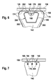
- FIG. 8 is an embodiment of an image-sensitive surface of a spatially resolving imaging sensor 118, which is also used as an optical sensor 140 of the secondary optical sensor 138, shown.
- the spatially resolving imaging sensor 118 has a resolution of 640x480 pixels in this embodiment.
- the image area is subdivided into a primary image area 178, in which the receiving area 120 of the camera 112 is imaged, and a secondary image area 182, in which the viewing area 180 of the secondary optical sensor 138 is imaged.
- the secondary image area 182 is selected in its width to height ratio such that this ratio is very large. In the example in FIG. 8 this is a ratio of 640 to 30 pixels, ie approximately a ratio of 21.
- the transition between the primary image area 178 and the secondary image area 182 on the spatially resolving imaging sensor 118 should be as clearly as possible separated by the image processing, so that the sensory area, and if possible only this, as much as possible secondary light 144 receives.
- the windshield 126 should not typically have such a large width-to-height ratio, for example, raindrops produce a round image to a first approximation. This clarifies the meaning and the advantages that the design of the light guide 142 has as a width-to-height ratio changing element.
- FIG. 8 as an alternative or in addition to the rectangular secondary image area 182 feasible embodiment, nor a plurality disjunkter secondary image areas shown 182, which are exemplified as four dashed ovals.
- This example is intended to clarify that the secondary image area 182 does not necessarily have to be completely separated from the primary image area 178.
- the spatial separation of the light of a plurality of light sources 168 and / or the splitting of the luminous flux of the light 202 of these light sources 168, which, for example, above with reference to FIGS. 7 and 8th For example, to generate such disjoint secondary image areas 182 as described in U.S. Pat FIG. 8 dashed lines are used.
- these secondary image areas 182 are located in a region of the primary image area 178, which is usually dark, they can be separated from the image of the camera 112 by appropriate image processing measures. Also, a temporal scheme for separation can be used, as described in more detail below.
- Images on the spatial resolution imaging sensor 118 may in many cases be taken, for example, line by line. Such methods are often referred to as "rolling shutter".
- rolling shutter In this case, for example, by synchronizing the at least one light source 168 with a recording algorithm of the spatially resolving imaging sensor 118, it is possible for a reflection image from the windshield 126 to be clearly assigned to a specific range of image lines of the spatially resolving imaging sensor 118.
- this method can also be used within the scope of the camera module 110 according to the invention.
- the method has the disadvantage that, if this area of the secondary image 182 coincides with a brightly illuminated area of the primary image area 178, an evaluation is difficult at these locations.
- a line-by-line redundancy can also be achieved by short-term repeated illumination of the windshield 126, as described by the spatial redundancy provided by a plurality of light paths and / or multiple light sources. This is shown schematically in the image acquisition plan in FIG. 9 exemplified.
- FIG. 9 three time axes are designated by t.
- t In each case at times t0 begins an image recording, wherein the distance T between successive times t0 is also referred to as image repetition time.
- a conventional image-synchronous exposure scheme is applied, which in principle can also be implemented within the scope of the present invention. This is achieved by an optional synchronization (in FIG. 9 denoted by reference numeral 208), an exposure pulse is switched in which the light intensity of the light source 168 is switched from zero (or a small offset) to an intensity 10 in the short term. During this time, image information of the secondary optical sensor 138 is captured.
- FIG. 9 an image pickup method with a flashlight pattern 212 indicated by numeral 210 is shown. Again, this flash pattern 212 may again (in FIG. 9 not shown) at the beginning t0 of the image recording to be synchronized.
- FIG. 8 A result of such imaging of the secondary optical sensor 138 having a flash pattern 212 is also shown in FIG. 8 shown here, optionally here in addition to the splitting of the secondary image area 182 into a plurality of partial areas, which in FIG. 8 are shown in dashed lines. It can be seen that the in FIG. 8 in each case designated by the reference numeral 214, the total irradiated area of the subareas of the secondary image area 182 is subdivided into a plurality of strip-type used areas 216. In this way are in the in FIG. 8 shown image redundant information of the optical secondary sensor 138 included, which can be separated, for example, computationally.
- the used areas 216 occur as disturbances in the primary image area 178, the payload of which can be determined, for example, by means of appropriate correlation techniques.
- the available image-sensitive surface of the position-sensitive imaging sensor 118 can be optimally used for both use the primary function of the camera 112 as well as the secondary function of the optical secondary sensor 138.
Landscapes
- Engineering & Computer Science (AREA)
- Multimedia (AREA)
- Signal Processing (AREA)
- Studio Devices (AREA)
Applications Claiming Priority (1)
| Application Number | Priority Date | Filing Date | Title |
|---|---|---|---|
| DE102008044003A DE102008044003A1 (de) | 2008-11-24 | 2008-11-24 | Kameramodul mit Mehrfachfunktion |
Publications (2)
| Publication Number | Publication Date |
|---|---|
| EP2189340A2 true EP2189340A2 (fr) | 2010-05-26 |
| EP2189340A3 EP2189340A3 (fr) | 2012-06-20 |
Family
ID=41698000
Family Applications (1)
| Application Number | Title | Priority Date | Filing Date |
|---|---|---|---|
| EP09171441A Ceased EP2189340A3 (fr) | 2008-11-24 | 2009-09-28 | Module de caméra doté de fonctions multiples |
Country Status (2)
| Country | Link |
|---|---|
| EP (1) | EP2189340A3 (fr) |
| DE (1) | DE102008044003A1 (fr) |
Cited By (17)
| Publication number | Priority date | Publication date | Assignee | Title |
|---|---|---|---|---|
| CN102566212A (zh) * | 2010-11-05 | 2012-07-11 | 罗伯特·博世有限公司 | 摄像机装置和用于运行机动车的摄像机装置的方法 |
| WO2013007701A1 (fr) * | 2011-07-12 | 2013-01-17 | Robert Bosch Gmbh | Système de caméra destiné à être utilisé dans un véhicule et véhicule équipé d'un tel système de caméra |
| EP2603006A1 (fr) * | 2011-12-09 | 2013-06-12 | Robert Bosch Gmbh | Dispositif de commande pour une installation de surveillance de l'environnement d'un véhicule |
| CN103376243A (zh) * | 2012-04-18 | 2013-10-30 | 原相科技股份有限公司 | 雨刷控制装置、光学雨滴检测装置及其检测方法 |
| WO2014005585A1 (fr) * | 2012-07-05 | 2014-01-09 | Continental Automotive Gmbh | Système de caméra pour identifier l'état d'une vitre de véhicule |
| CN103826938A (zh) * | 2011-09-22 | 2014-05-28 | 罗伯特·博世有限公司 | 用于车辆的图像检测设备 |
| WO2014127776A1 (fr) * | 2013-02-21 | 2014-08-28 | Conti Temic Microelectronic Gmbh | Dispositif optique de détection de pluie pour un véhicule |
| WO2014146865A1 (fr) * | 2013-03-22 | 2014-09-25 | Robert Bosch Gmbh | Système de caméra pour véhicule et véhicule équipé d'un tel système de caméra |
| US20150070499A1 (en) * | 2012-01-09 | 2015-03-12 | Volker Roelke | Camera system, in particular for a vehicle |
| EP2766227A4 (fr) * | 2011-10-11 | 2015-08-19 | Autoliv Dev | Agencement de caméra |
| US9626570B2 (en) | 2013-09-26 | 2017-04-18 | Denso Corporation | Vehicle control system and image sensor |
| US9690997B2 (en) | 2011-06-06 | 2017-06-27 | Denso Corporation | Recognition object detecting apparatus |
| US10046716B2 (en) * | 2011-02-10 | 2018-08-14 | Denso Corporation | In-vehicle camera and vehicle control system |
| CN109765674A (zh) * | 2017-11-10 | 2019-05-17 | 株式会社电装 | 摄像装置模块 |
| DE102020132427A1 (de) | 2020-12-07 | 2022-06-09 | Valeo Schalter Und Sensoren Gmbh | Kraftfahrzeugkameraeinheit, Kraftfahrzeug und Fahrerassistenzsystem |
| US20240246514A1 (en) * | 2021-05-20 | 2024-07-25 | Valeo Schalter Und Sensoren Gmbh | Rain sensor system, vehicle and method for detecting rain |
| WO2025252491A1 (fr) * | 2024-06-04 | 2025-12-11 | Valeo Schalter Und Sensoren Gmbh | Dispositif de détection optique, comprenant au moins un récepteur d'image et au moins un dispositif de réception secondaire optique |
Families Citing this family (14)
| Publication number | Priority date | Publication date | Assignee | Title |
|---|---|---|---|---|
| US9380219B2 (en) | 2011-04-20 | 2016-06-28 | Magna Electronics Inc. | Angular filter for vehicle mounted cameras |
| US9871971B2 (en) | 2011-08-02 | 2018-01-16 | Magma Electronics Inc. | Vehicle vision system with light baffling system |
| US9596387B2 (en) | 2011-08-02 | 2017-03-14 | Magna Electronics Inc. | Vehicular camera system |
| DE102011116128A1 (de) | 2011-10-15 | 2013-04-18 | Volkswagen Aktiengesellschaft | Verfahren für ein Bildverarbeitungssystemfür ein Fahrzeug |
| DE102013100292A1 (de) * | 2013-01-11 | 2014-07-24 | Conti Temic Microelectronic Gmbh | Beleuchtung zur Detektion von Regentropfen auf einer Scheibe mittels einer Kamera |
| DE102013000751B4 (de) | 2013-01-17 | 2024-02-29 | HELLA GmbH & Co. KGaA | Sensorvorrichtung zum Erfassen von Feuchtigkeit auf einer Scheibe |
| DE102013210890A1 (de) | 2013-06-11 | 2014-12-11 | Robert Bosch Gmbh | Verfahren und Vorrichtung zum Erkennen eines Wetter-Phänomens |
| DE102013211735A1 (de) * | 2013-06-21 | 2014-12-24 | Continental Automotive Gmbh | Vorrichtung zur Feuchtigkeitserkennung |
| US9896039B2 (en) | 2014-05-09 | 2018-02-20 | Magna Electronics Inc. | Vehicle vision system with forward viewing camera |
| DE102017217072B4 (de) | 2017-09-26 | 2023-08-31 | Volkswagen Aktiengesellschaft | Verfahren zum Erkennen eines Witterungsverhältnisses in einer Umgebung eines Kraftfahrzeugs sowie Steuervorrichtung und Kraftfahrzeug |
| DE102020204238A1 (de) | 2020-04-01 | 2021-10-07 | Conti Temic Microelectronic Gmbh | Sensorbaugruppe für ein Fahrzeug |
| DE102020115739B4 (de) | 2020-06-15 | 2023-01-12 | Bayerische Motoren Werke Aktiengesellschaft | Streulichtblende für einen optischen Sensor eines Fahrzeugs umfassend eine Lichtleiteinrichtung, Sensoranordnung sowie Fahrzeug |
| DE102021109171A1 (de) | 2021-04-13 | 2022-10-13 | Valeo Schalter Und Sensoren Gmbh | Regensensorsystem und fahrzeug |
| DE102023106661A1 (de) | 2023-03-16 | 2024-09-19 | Valeo Schalter Und Sensoren Gmbh | Frontkameraanordnung für ein Kraftfahrzeug und Kraftfahrzeug |
Citations (1)
| Publication number | Priority date | Publication date | Assignee | Title |
|---|---|---|---|---|
| DE102004015040A1 (de) | 2004-03-26 | 2005-10-13 | Robert Bosch Gmbh | Kamera in einem Kraftfahrzeug |
Family Cites Families (3)
| Publication number | Priority date | Publication date | Assignee | Title |
|---|---|---|---|---|
| DE19742093A1 (de) * | 1997-09-24 | 1999-03-25 | Kostal Leopold Gmbh & Co Kg | Photoelektrisches Sensorarray |
| DE19909986C2 (de) * | 1999-03-06 | 2002-08-29 | Kostal Leopold Gmbh & Co Kg | Optoelektronische Überwachungseinrichtung für ein Kraftfahrzeug |
| EP1923695A1 (fr) * | 2006-11-20 | 2008-05-21 | Delphi Technologies, Inc. | Dispositif destiné à l'enregistrement de l'humidité sur un disque |
-
2008
- 2008-11-24 DE DE102008044003A patent/DE102008044003A1/de not_active Ceased
-
2009
- 2009-09-28 EP EP09171441A patent/EP2189340A3/fr not_active Ceased
Patent Citations (1)
| Publication number | Priority date | Publication date | Assignee | Title |
|---|---|---|---|---|
| DE102004015040A1 (de) | 2004-03-26 | 2005-10-13 | Robert Bosch Gmbh | Kamera in einem Kraftfahrzeug |
Cited By (31)
| Publication number | Priority date | Publication date | Assignee | Title |
|---|---|---|---|---|
| CN102566212A (zh) * | 2010-11-05 | 2012-07-11 | 罗伯特·博世有限公司 | 摄像机装置和用于运行机动车的摄像机装置的方法 |
| US9676329B2 (en) | 2010-11-05 | 2017-06-13 | Robert Bosch Gmbh | Camera system and method for operating a camera system for a motor vehicle |
| CN102566212B (zh) * | 2010-11-05 | 2017-03-01 | 罗伯特·博世有限公司 | 摄像机装置和用于运行机动车的摄像机装置的方法 |
| US10377322B2 (en) | 2011-02-10 | 2019-08-13 | Denso Corporation | In-vehicle camera and vehicle control system |
| US10046716B2 (en) * | 2011-02-10 | 2018-08-14 | Denso Corporation | In-vehicle camera and vehicle control system |
| US10406994B2 (en) | 2011-02-10 | 2019-09-10 | Denso Corporation | In-vehicle camera and vehicle control system |
| US9690997B2 (en) | 2011-06-06 | 2017-06-27 | Denso Corporation | Recognition object detecting apparatus |
| WO2013007701A1 (fr) * | 2011-07-12 | 2013-01-17 | Robert Bosch Gmbh | Système de caméra destiné à être utilisé dans un véhicule et véhicule équipé d'un tel système de caméra |
| CN103826938A (zh) * | 2011-09-22 | 2014-05-28 | 罗伯特·博世有限公司 | 用于车辆的图像检测设备 |
| EP2766227A4 (fr) * | 2011-10-11 | 2015-08-19 | Autoliv Dev | Agencement de caméra |
| CN103158617A (zh) * | 2011-12-09 | 2013-06-19 | 罗伯特·博世有限公司 | 用于车辆周围环境监测装置的控制装置 |
| US9386284B2 (en) | 2011-12-09 | 2016-07-05 | Robert Bosch Gmbh | Actuating device for a device for monitoring the vehicle surroundings |
| EP2603006A1 (fr) * | 2011-12-09 | 2013-06-12 | Robert Bosch Gmbh | Dispositif de commande pour une installation de surveillance de l'environnement d'un véhicule |
| US20150070499A1 (en) * | 2012-01-09 | 2015-03-12 | Volker Roelke | Camera system, in particular for a vehicle |
| CN103376243B (zh) * | 2012-04-18 | 2015-10-28 | 原相科技股份有限公司 | 雨刷控制装置、光学雨滴检测装置及其检测方法 |
| CN103376243A (zh) * | 2012-04-18 | 2013-10-30 | 原相科技股份有限公司 | 雨刷控制装置、光学雨滴检测装置及其检测方法 |
| WO2014005585A1 (fr) * | 2012-07-05 | 2014-01-09 | Continental Automotive Gmbh | Système de caméra pour identifier l'état d'une vitre de véhicule |
| WO2014127776A1 (fr) * | 2013-02-21 | 2014-08-28 | Conti Temic Microelectronic Gmbh | Dispositif optique de détection de pluie pour un véhicule |
| CN105283355A (zh) * | 2013-03-22 | 2016-01-27 | 罗伯特·博世有限公司 | 用于车辆的摄像机装置和具有该种摄像机装置的车辆 |
| US10106102B2 (en) | 2013-03-22 | 2018-10-23 | Robert Bosch Gmbh | Camera assembly for a vehicle, and vehicle having such a camera assembly |
| CN105283355B (zh) * | 2013-03-22 | 2017-10-17 | 罗伯特·博世有限公司 | 用于车辆的摄像机装置和具有该种摄像机装置的车辆 |
| WO2014146865A1 (fr) * | 2013-03-22 | 2014-09-25 | Robert Bosch Gmbh | Système de caméra pour véhicule et véhicule équipé d'un tel système de caméra |
| US9626570B2 (en) | 2013-09-26 | 2017-04-18 | Denso Corporation | Vehicle control system and image sensor |
| CN109765674A (zh) * | 2017-11-10 | 2019-05-17 | 株式会社电装 | 摄像装置模块 |
| CN109765668A (zh) * | 2017-11-10 | 2019-05-17 | 株式会社电装 | 摄像装置模块 |
| CN109765668B (zh) * | 2017-11-10 | 2022-03-08 | 株式会社电装 | 摄像装置模块 |
| CN109765674B (zh) * | 2017-11-10 | 2022-11-08 | 株式会社电装 | 摄像装置模块 |
| DE102020132427A1 (de) | 2020-12-07 | 2022-06-09 | Valeo Schalter Und Sensoren Gmbh | Kraftfahrzeugkameraeinheit, Kraftfahrzeug und Fahrerassistenzsystem |
| US20240246514A1 (en) * | 2021-05-20 | 2024-07-25 | Valeo Schalter Und Sensoren Gmbh | Rain sensor system, vehicle and method for detecting rain |
| US12589716B2 (en) * | 2021-05-20 | 2026-03-31 | Valeo Schalter Und Sensoren Gmbh | Rain sensor system, vehicle and method for detecting rain |
| WO2025252491A1 (fr) * | 2024-06-04 | 2025-12-11 | Valeo Schalter Und Sensoren Gmbh | Dispositif de détection optique, comprenant au moins un récepteur d'image et au moins un dispositif de réception secondaire optique |
Also Published As
| Publication number | Publication date |
|---|---|
| EP2189340A3 (fr) | 2012-06-20 |
| DE102008044003A1 (de) | 2010-05-27 |
Similar Documents
| Publication | Publication Date | Title |
|---|---|---|
| EP2189340A2 (fr) | Module de caméra doté de fonctions multiples | |
| EP1991450B1 (fr) | Ensemble caméra pour véhicule à moteur | |
| EP2384292B1 (fr) | Système de caméra pour un véhicule automobile et véhicule automobile comprenant un système de caméra | |
| DE102012200200B4 (de) | Kamerasystem, insbesondere für ein Fahrzeug, sowie ein Fahrzeug | |
| DE102011010334B4 (de) | Kamerasystem und Verfahren zur Beobachtung von Objekten in großer Entfernung, insbesondere zur Überwachung von Zielobjekten bei Nacht, Dunst, Staub oder Regen | |
| DE102017109905B4 (de) | Scheinwerfer mit integriertem Lidar | |
| DE102014203335A1 (de) | Lichtmodul eines Kraftfahrzeugscheinwerfers und Scheinwerfer mit einem solchen Lichtmodul | |
| EP2646802A1 (fr) | Détection de gouttes de pluie sur une vitre au moyen d'une caméra et d'un éclairage | |
| EP1580092A2 (fr) | Caméra pour un véhicule automobile | |
| DE102013108824A1 (de) | Sensoranordnung zur Erfassung von Bediengesten an Fahrzeugen | |
| DE102010029176A1 (de) | Kraftfahrzeugscheinwerfer mit einem Halbleiterlichtquellen, eine Primäroptik und eine Sekundäroptik aufweisenden Lichtmodul | |
| DE202005018197U1 (de) | Laser-Entfernungsmessungsvorrichtung | |
| DE102015223024A1 (de) | Laserentfernungsmessgerät | |
| DE102018118584A1 (de) | Fahrzeugscheinwerfer mit LIDAR-Modul | |
| DE102017117591A1 (de) | Kraftfahrzeugscheinwerferanordnung | |
| DE102012011847A1 (de) | Nachtsichtsystem für ein Kraftfahrzeug | |
| DE102014217749A1 (de) | Streulichtblende | |
| EP3077255B1 (fr) | Éclairage destiné à détecter des gouttes de pluie sur une vitre au moyen d'une caméra | |
| DE102012111199A1 (de) | Optische Vorrichtung mit multifokaler Bilderfassung | |
| DE102019206379B4 (de) | Beleuchtungsvorrichtung mit einem als Lichtleiter ausgebildeten flächigen Trägermedium | |
| WO2012103874A1 (fr) | Système à caméra servant à capter des objets mobiles se trouvant à grande distance et à suivre leur trajectoire | |
| DE102019218220A1 (de) | LIDAR-Sensor und Verfahren zur optischen Erfassung eines Sichtfeldes | |
| DE202006014939U1 (de) | Optiksystem zur Erfassung einer dreidimensionalen Superweitwinkelszene | |
| DE102015218822A1 (de) | Lichtlaufzeitkamera mit verstellbarer Blende | |
| DE102006040812A1 (de) | Empfangsvorrichtung für Laserscanner |
Legal Events
| Date | Code | Title | Description |
|---|---|---|---|
| PUAI | Public reference made under article 153(3) epc to a published international application that has entered the european phase |
Free format text: ORIGINAL CODE: 0009012 |
|
| AK | Designated contracting states |
Kind code of ref document: A2 Designated state(s): AT BE BG CH CY CZ DE DK EE ES FI FR GB GR HR HU IE IS IT LI LT LU LV MC MK MT NL NO PL PT RO SE SI SK SM TR |
|
| AX | Request for extension of the european patent |
Extension state: AL BA RS |
|
| PUAL | Search report despatched |
Free format text: ORIGINAL CODE: 0009013 |
|
| AK | Designated contracting states |
Kind code of ref document: A3 Designated state(s): AT BE BG CH CY CZ DE DK EE ES FI FR GB GR HR HU IE IS IT LI LT LU LV MC MK MT NL NO PL PT RO SE SI SK SM TR |
|
| AX | Request for extension of the european patent |
Extension state: AL BA RS |
|
| RIC1 | Information provided on ipc code assigned before grant |
Ipc: H04N 5/225 20060101ALI20120516BHEP Ipc: B60S 1/08 20060101AFI20120516BHEP |
|
| 17P | Request for examination filed |
Effective date: 20121220 |
|
| 17Q | First examination report despatched |
Effective date: 20130221 |
|
| STAA | Information on the status of an ep patent application or granted ep patent |
Free format text: STATUS: THE APPLICATION HAS BEEN REFUSED |
|
| 18R | Application refused |
Effective date: 20170318 |