EP2189349A2 - Procédé et dispositif de compensation de l'angle de roulis - Google Patents
Procédé et dispositif de compensation de l'angle de roulis Download PDFInfo
- Publication number
- EP2189349A2 EP2189349A2 EP09175393A EP09175393A EP2189349A2 EP 2189349 A2 EP2189349 A2 EP 2189349A2 EP 09175393 A EP09175393 A EP 09175393A EP 09175393 A EP09175393 A EP 09175393A EP 2189349 A2 EP2189349 A2 EP 2189349A2
- Authority
- EP
- European Patent Office
- Prior art keywords
- image
- determined
- model
- displacement vectors
- camera
- Prior art date
- Legal status (The legal status is an assumption and is not a legal conclusion. Google has not performed a legal analysis and makes no representation as to the accuracy of the status listed.)
- Withdrawn
Links
Images

Classifications
-
- B—PERFORMING OPERATIONS; TRANSPORTING
- B60—VEHICLES IN GENERAL
- B60W—CONJOINT CONTROL OF VEHICLE SUB-UNITS OF DIFFERENT TYPE OR DIFFERENT FUNCTION; CONTROL SYSTEMS SPECIALLY ADAPTED FOR HYBRID VEHICLES; ROAD VEHICLE DRIVE CONTROL SYSTEMS FOR PURPOSES NOT RELATED TO THE CONTROL OF A PARTICULAR SUB-UNIT
- B60W40/00—Estimation or calculation of non-directly measurable driving parameters for road vehicle drive control systems not related to the control of a particular sub unit, e.g. by using mathematical models
- B60W40/10—Estimation or calculation of non-directly measurable driving parameters for road vehicle drive control systems not related to the control of a particular sub unit, e.g. by using mathematical models related to vehicle motion
- B60W40/11—Pitch movement
-
- B—PERFORMING OPERATIONS; TRANSPORTING
- B60—VEHICLES IN GENERAL
- B60W—CONJOINT CONTROL OF VEHICLE SUB-UNITS OF DIFFERENT TYPE OR DIFFERENT FUNCTION; CONTROL SYSTEMS SPECIALLY ADAPTED FOR HYBRID VEHICLES; ROAD VEHICLE DRIVE CONTROL SYSTEMS FOR PURPOSES NOT RELATED TO THE CONTROL OF A PARTICULAR SUB-UNIT
- B60W40/00—Estimation or calculation of non-directly measurable driving parameters for road vehicle drive control systems not related to the control of a particular sub unit, e.g. by using mathematical models
- B60W40/10—Estimation or calculation of non-directly measurable driving parameters for road vehicle drive control systems not related to the control of a particular sub unit, e.g. by using mathematical models related to vehicle motion
- B60W40/105—Speed
-
- B—PERFORMING OPERATIONS; TRANSPORTING
- B60—VEHICLES IN GENERAL
- B60W—CONJOINT CONTROL OF VEHICLE SUB-UNITS OF DIFFERENT TYPE OR DIFFERENT FUNCTION; CONTROL SYSTEMS SPECIALLY ADAPTED FOR HYBRID VEHICLES; ROAD VEHICLE DRIVE CONTROL SYSTEMS FOR PURPOSES NOT RELATED TO THE CONTROL OF A PARTICULAR SUB-UNIT
- B60W40/00—Estimation or calculation of non-directly measurable driving parameters for road vehicle drive control systems not related to the control of a particular sub unit, e.g. by using mathematical models
- B60W40/10—Estimation or calculation of non-directly measurable driving parameters for road vehicle drive control systems not related to the control of a particular sub unit, e.g. by using mathematical models related to vehicle motion
- B60W40/112—Roll movement
-
- B—PERFORMING OPERATIONS; TRANSPORTING
- B60—VEHICLES IN GENERAL
- B60W—CONJOINT CONTROL OF VEHICLE SUB-UNITS OF DIFFERENT TYPE OR DIFFERENT FUNCTION; CONTROL SYSTEMS SPECIALLY ADAPTED FOR HYBRID VEHICLES; ROAD VEHICLE DRIVE CONTROL SYSTEMS FOR PURPOSES NOT RELATED TO THE CONTROL OF A PARTICULAR SUB-UNIT
- B60W40/00—Estimation or calculation of non-directly measurable driving parameters for road vehicle drive control systems not related to the control of a particular sub unit, e.g. by using mathematical models
- B60W40/10—Estimation or calculation of non-directly measurable driving parameters for road vehicle drive control systems not related to the control of a particular sub unit, e.g. by using mathematical models related to vehicle motion
- B60W40/114—Yaw movement
-
- G—PHYSICS
- G06—COMPUTING OR CALCULATING; COUNTING
- G06V—IMAGE OR VIDEO RECOGNITION OR UNDERSTANDING
- G06V20/00—Scenes; Scene-specific elements
- G06V20/50—Context or environment of the image
- G06V20/56—Context or environment of the image exterior to a vehicle by using sensors mounted on the vehicle
- G06V20/58—Recognition of moving objects or obstacles, e.g. vehicles or pedestrians; Recognition of traffic objects, e.g. traffic signs, traffic lights or roads
-
- G—PHYSICS
- G06—COMPUTING OR CALCULATING; COUNTING
- G06V—IMAGE OR VIDEO RECOGNITION OR UNDERSTANDING
- G06V20/00—Scenes; Scene-specific elements
- G06V20/50—Context or environment of the image
- G06V20/56—Context or environment of the image exterior to a vehicle by using sensors mounted on the vehicle
- G06V20/588—Recognition of the road, e.g. of lane markings; Recognition of the vehicle driving pattern in relation to the road
-
- B—PERFORMING OPERATIONS; TRANSPORTING
- B60—VEHICLES IN GENERAL
- B60G—VEHICLE SUSPENSION ARRANGEMENTS
- B60G2400/00—Indexing codes relating to detected, measured or calculated conditions or factors
- B60G2400/05—Attitude
- B60G2400/051—Angle
- B60G2400/0511—Roll angle
-
- B—PERFORMING OPERATIONS; TRANSPORTING
- B60—VEHICLES IN GENERAL
- B60G—VEHICLE SUSPENSION ARRANGEMENTS
- B60G2401/00—Indexing codes relating to the type of sensors based on the principle of their operation
- B60G2401/14—Photo or light sensitive means, e.g. Infrared
- B60G2401/142—Visual Display Camera, e.g. LCD
-
- B—PERFORMING OPERATIONS; TRANSPORTING
- B60—VEHICLES IN GENERAL
- B60T—VEHICLE BRAKE CONTROL SYSTEMS OR PARTS THEREOF; BRAKE CONTROL SYSTEMS OR PARTS THEREOF, IN GENERAL; ARRANGEMENT OF BRAKING ELEMENTS ON VEHICLES IN GENERAL; PORTABLE DEVICES FOR PREVENTING UNWANTED MOVEMENT OF VEHICLES; VEHICLE MODIFICATIONS TO FACILITATE COOLING OF BRAKES
- B60T2230/00—Monitoring, detecting special vehicle behaviour; Counteracting thereof
- B60T2230/03—Overturn, rollover
-
- B—PERFORMING OPERATIONS; TRANSPORTING
- B60—VEHICLES IN GENERAL
- B60W—CONJOINT CONTROL OF VEHICLE SUB-UNITS OF DIFFERENT TYPE OR DIFFERENT FUNCTION; CONTROL SYSTEMS SPECIALLY ADAPTED FOR HYBRID VEHICLES; ROAD VEHICLE DRIVE CONTROL SYSTEMS FOR PURPOSES NOT RELATED TO THE CONTROL OF A PARTICULAR SUB-UNIT
- B60W2420/00—Indexing codes relating to the type of sensors based on the principle of their operation
- B60W2420/40—Photo, light or radio wave sensitive means, e.g. infrared sensors
- B60W2420/403—Image sensing, e.g. optical camera
-
- B—PERFORMING OPERATIONS; TRANSPORTING
- B60—VEHICLES IN GENERAL
- B60W—CONJOINT CONTROL OF VEHICLE SUB-UNITS OF DIFFERENT TYPE OR DIFFERENT FUNCTION; CONTROL SYSTEMS SPECIALLY ADAPTED FOR HYBRID VEHICLES; ROAD VEHICLE DRIVE CONTROL SYSTEMS FOR PURPOSES NOT RELATED TO THE CONTROL OF A PARTICULAR SUB-UNIT
- B60W2520/00—Input parameters relating to overall vehicle dynamics
- B60W2520/18—Roll
-
- B—PERFORMING OPERATIONS; TRANSPORTING
- B60—VEHICLES IN GENERAL
- B60W—CONJOINT CONTROL OF VEHICLE SUB-UNITS OF DIFFERENT TYPE OR DIFFERENT FUNCTION; CONTROL SYSTEMS SPECIALLY ADAPTED FOR HYBRID VEHICLES; ROAD VEHICLE DRIVE CONTROL SYSTEMS FOR PURPOSES NOT RELATED TO THE CONTROL OF A PARTICULAR SUB-UNIT
- B60W2720/00—Output or target parameters relating to overall vehicle dynamics
- B60W2720/18—Roll
Definitions
- the invention relates to a method and a device for compensating a roll angle during operation of a camera-assisted driver assistance system in a motor vehicle.
- Modern driver assistance systems are regularly coupled with cameras and are supported by means of image processing of the images taken by the camera.
- the cameras detect speed limits and / or lane markings.
- a lane departure warning system analyzes the images taken by the camera for lane markings and alerts the driver of the motor vehicle if it overruns the lane markings delimiting the road.
- the driver assistance system and / or the image processing system knows the exact orientation of the camera with respect to the roadway. It is particularly advantageous if an image perpendicular to a lower edge of the captured images is parallel to a surface normal on the road. Alternatively, it is sufficient if an angle between the surface normal of the road surface and the image normal is known, so that this angle can be taken into account in the image analysis.
- the angle between the surface normal of the road surface and the image normal in the image plane of the camera can be at a flat road, for example, due to an imprecise built-in camera, due to a tank filling due to uneven loading of the motor vehicle and / or due to an uneven distribution of persons in the motor vehicle.
- the angle corresponds seen in the direction of travel a roll angle of the motor vehicle and is referred to in this context below as a roll angle.
- the invention is characterized by a method and a device for compensating a roll angle when operating a camera-based driver assistance system in a motor vehicle.
- a first image is acquired with the aid of a camera of the motor vehicle and the coordinates of at least two characteristic points of the first image are determined.
- a second image is acquired with the aid of the camera and the coordinates of the two characteristic points in the second image are determined.
- two displacement vectors are determined which are each representative of a displacement of the characteristic points in an image plane of the camera, in particular from the first image to the second image.
- two model displacement vectors are determined, each of which model the displacement of the characteristic points in the image plane.
- a reference vector is determined.
- the roll angle is determined.
- the images may be the same as full images captured by the camera or only parts of it. Furthermore, the images are preferably detected in the direction of travel of the motor vehicle. The movement of the motor vehicle between the recording of the first and the second image is preferably characterized by a speed of the motor vehicle.
- the reference vector is a model normal vector which is perpendicular to the road surface and thus corresponds to a surface normal of the roadway.
- the roll angle is preferably determined by projecting the model normal vector onto the image plane and comparing the projected model normal vector with an image perpendicular in the image plane of the camera. The roll angle in this context corresponds to the angle between the projected model normal vector and the image normal.
- three or more actual displacement vectors and correspondingly three or more model displacement vectors are determined, from which then the model normal vector is determined.
- This can be a mathematical system of equations be determined to determine the model normal vector, which may contribute to a particularly precise determination of the model normal vector.
- At least one of the actual displacement vectors is discarded and not considered further, in particular the actual displacement vector whose angular deviation from the one or more averaged vectors is greatest. This can help to exclude incorrectly determined actual displacement vectors and not to be taken into account in the determination of the model displacement vectors and the model normal vector and thus contributes to the particularly precise determination of the model normal vector.
- the model displacement vectors are dependent on the coordinates of the model normal vector.
- the model normal vector is determined by minimizing, by varying the coordinates of the model normal vector, a function value of a function corresponding to a distinction between all the considered actual displacement vectors and the corresponding model displacement vectors. This contributes to the fact that the model normal vector is determined with a particularly low application cost.
- the difference between the actual displacement vectors and the corresponding model displacement vectors may be expressed, for example, by an amount of the differences of the related vectors and then adding up all the amounts.
- the model normal vector corresponds optimally to the surface normal on the road surface if and only if the function value is minimal.
- the determined roll angle is used for image correction of the camera image.
- the determined roll angle can be automatically made available to the driver assistance system. This contributes to a precise functioning of the driver assistance system and thus to the safety of the driver of the motor vehicle.
- model displacement vectors are determined by means of the general equation of motion, the mapping equation of a pinhole camera and the general plane equation. This also contributes to the low application effort when programming the method.
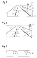
- FIG. 1 shows a road 20 with lane markings 24.
- the road 20 is visible to a horizon 26.
- a traffic sign 28 can be seen.
- a camera in particular a monocamera, which is arranged in a motor vehicle
- a first image 32 is preferably recorded in the direction of travel of the motor vehicle.
- characteristic points 30 are searched for by means of an image recognition system.
- the image recognition system may, for example, have a corner finder which searches for characteristic points 30 on the road 20 on the basis of distinctive gray value transitions.
- characteristic points 30 are preferably sought, which have the greatest possible distance from one another.
- FIG. 2 shows a view of the road 20 shortly after taking the first image 32.
- a second image 33 is taken by the camera.
- the image recognition system searches again for the characteristic points 30, which are now shifted relative to the first image 32 due to an interim movement of the motor vehicle in the second image 33.
- an image analysis system may determine first to fourth actual displacement vectors IV_1 to IV_4 representative of the displacement of the characteristic points 30 in the image plane of the camera between the capture of the first image 32 and the acquisition of the second image 33 more actual displacement vectors IV_1 to IV_4 determined.
- one or more of the actual displacement vectors IV_1 to IV_4 can also be discarded after their determination, for example if they have an angle which deviates greatly from one or more averaged angles of the other actual displacement vectors IV_1 to IV_4. This avoids that incorrectly determined actual displacement vectors IV_1 to IV_4 are taken into account in the further calculation.
- model displacement vectors MV_N Based on the coordinates of the characteristic points 30 of the first image 32, in addition to the actual displacement vectors IV_1 to IV_4 model displacement vectors MV_N based on the in FIG. 4 shown formulas F1 to F4 determined.
- the determination of the model displacement vectors MV_N is only briefly outlined below.
- the formulas F2 and F3 show a relationship between two-dimensional coordinates u 1 and u 2 , for example, one of the characteristic points 30, in the image plane of the camera and corresponding three-dimensional coordinates p 1 , p 2 , p 3 , for example, the corresponding characteristic point 30 the real roadway.
- the formulas F2 and F3 are basically also referred to as imaging equations of a pinhole camera. On the basis of the imaging equations of the lock camera, the three-dimensional ones can thus be determined starting from the characteristic points 30 recorded in the first image 32 Coordinates are determined in reality.
- R denotes a rotation matrix and t a translation vector, which depend on a movement of the motor vehicle.
- the rotation matrix R is simplified into a unit matrix and the translation vector has only one non-zero component and which depends on the speed of the motor vehicle.
- the three-dimensional coordinates q 1 , q 2 , q 3 , of the characteristic points 30 after the movement of the motor vehicle between the recording of the first image 32 and the recording of the second image 33 can be determined.
- the general plane equation is shown satisfying all points of a plane, where b 1 to b 3 are the coordinates of the normal vector of the corresponding plane.
- the model displacement vectors MV_N which are representative of the displacement of the characteristic points 30 from the first to the second image 32, 33 can now be determined as a function of a model normal vector b about the displacement of the characteristic points 30 in reality in dependence of the movement of the motor vehicle.
- the displacement of the characteristic points 30 between the images of the images 32, 33 on the one hand determined by simply measuring in the image plane, which the actual displacement vectors IV_N and on the other hand by determining the real displacement of the characteristic points 30 on the real roadway relative to the motor vehicle and transformed to the image plane.
- the displacement of the characteristic points 30 due to the movement of the motor vehicle is determined in two different ways.
- a function according to formula F5 now represents the sum over the amounts of the differences of all model displacement vectors MV_N and actual displacement vectors IV_N. If this sum is minimal, then the model displacement vectors MV_N correspond particularly well to the actual displacement vectors. Furthermore, the sum can be minimized by varying the model normal vector b. Therefore, it is assumed that the model normal vector b corresponds to the actual normal vector on the road, especially the road 20, when the sum is minimum. In other words, the model displacement vectors MV_N are varied by variation of the model normal vector b until they correspond as closely as possible to the actual displacement vectors IV_N. Preferably, so many displacement vectors are determined on the basis of the two or more images and on the represented model that the equation according to the formula F5 is strongly overdetermined. This allows a particularly precise approach to the actual normal vector of the road surface.
- FIG. 5 schematically shows a projection of the determined model normal vector b on the screen level.
- the projected model normal vector b concludes with an image vertical 40 which is perpendicular to a lower image edge of the image plane 36 an angle, in particular the roll angle ⁇ .
- this can now be considered in the image analysis system and the image be rotated accordingly.
- the image is not changed, but the determined roll angle .alpha. Is made available to the driver assistance system and / or further vehicle systems, so that they can directly take into account, in particular compensate, the roll angle .alpha.
Landscapes
- Engineering & Computer Science (AREA)
- Physics & Mathematics (AREA)
- Automation & Control Theory (AREA)
- Mathematical Physics (AREA)
- Transportation (AREA)
- Mechanical Engineering (AREA)
- General Physics & Mathematics (AREA)
- Multimedia (AREA)
- Theoretical Computer Science (AREA)
- Traffic Control Systems (AREA)
- Image Analysis (AREA)
- Closed-Circuit Television Systems (AREA)
- Length Measuring Devices By Optical Means (AREA)
Applications Claiming Priority (1)
| Application Number | Priority Date | Filing Date | Title |
|---|---|---|---|
| DE102008058279A DE102008058279A1 (de) | 2008-11-20 | 2008-11-20 | Verfahren und Vorrichtung zur Kompensation eines Rollwinkels |
Publications (2)
| Publication Number | Publication Date |
|---|---|
| EP2189349A2 true EP2189349A2 (fr) | 2010-05-26 |
| EP2189349A3 EP2189349A3 (fr) | 2011-03-23 |
Family
ID=41718393
Family Applications (1)
| Application Number | Title | Priority Date | Filing Date |
|---|---|---|---|
| EP09175393A Withdrawn EP2189349A3 (fr) | 2008-11-20 | 2009-11-09 | Procédé et dispositif de compensation de l'angle de roulis |
Country Status (5)
| Country | Link |
|---|---|
| US (1) | US20100157058A1 (fr) |
| EP (1) | EP2189349A3 (fr) |
| JP (1) | JP2010193428A (fr) |
| KR (1) | KR20100056980A (fr) |
| DE (1) | DE102008058279A1 (fr) |
Cited By (3)
| Publication number | Priority date | Publication date | Assignee | Title |
|---|---|---|---|---|
| WO2013020550A3 (fr) * | 2011-08-05 | 2013-04-11 | Conti Temic Microelectronic Gmbh | Procédé de reconnaissance d'une voie de circulation au moyen d'une caméra |
| CN105973169A (zh) * | 2016-06-06 | 2016-09-28 | 北京信息科技大学 | 滚转角测量方法、装置和系统 |
| EP3159195A1 (fr) * | 2015-10-21 | 2017-04-26 | Continental Automotive GmbH | Dispositif d'assistance au conducteur pour un vehicule et procede destine a compenser un desequilibre du vehicule |
Families Citing this family (18)
| Publication number | Priority date | Publication date | Assignee | Title |
|---|---|---|---|---|
| JPH10299655A (ja) * | 1997-02-18 | 1998-11-10 | Calsonic Corp | 斜板式コンプレッサのピストンアセンブリ |
| DE102010063133A1 (de) | 2010-12-15 | 2012-06-21 | Robert Bosch Gmbh | Verfahren und System zur Bestimmung einer Eigenbewegung eines Fahrzeugs |
| DE102011101246A1 (de) | 2011-05-11 | 2012-11-15 | Conti Temic Microelectronic Gmbh | Redudante objektdetektion für fahrerassistenzsysteme |
| JP5821274B2 (ja) * | 2011-05-20 | 2015-11-24 | マツダ株式会社 | 移動体位置検出装置 |
| DE102012001950A1 (de) * | 2012-02-02 | 2013-08-08 | Daimler Ag | Verfahren zum Betreiben einer Kameraanordnung für ein Fahrzeug und Kameraanordnung |
| JP6141601B2 (ja) | 2012-05-15 | 2017-06-07 | 東芝アルパイン・オートモティブテクノロジー株式会社 | 車載カメラ自動キャリブレーション装置 |
| DE102013104256A1 (de) | 2013-04-26 | 2014-10-30 | Conti Temic Microelectronic Gmbh | Verfahren und Vorrichtung zur Schätzung der Anzahl von Fahrspuren |
| KR101592740B1 (ko) * | 2014-07-24 | 2016-02-15 | 현대자동차주식회사 | 차량용 광각카메라의 영상 왜곡 보정 장치 및 방법 |
| EP3176013B1 (fr) | 2015-12-01 | 2019-07-17 | Honda Research Institute Europe GmbH | Commande de suspension prédictif pour un véhicule à l'aide d'un capteur de caméra stéréo |
| EP3193306B8 (fr) | 2016-01-15 | 2019-01-23 | Aptiv Technologies Limited | Procédé et dispositif permettant d'estimer l'orientation d'une caméra par rapport à une surface de route |
| US10179607B2 (en) * | 2016-08-03 | 2019-01-15 | Aptiv Technologies Limited | Lane keeping system for autonomous vehicle in wind conditions using vehicle roll |
| KR102519100B1 (ko) * | 2017-01-27 | 2023-04-06 | 젠텍스 코포레이션 | 모터사이클 기울어짐에 대한 이미지 보상 |
| US11202055B2 (en) * | 2018-02-28 | 2021-12-14 | Blackberry Limited | Rapid ground-plane discrimination in stereoscopic images |
| US12085653B2 (en) * | 2019-04-09 | 2024-09-10 | Pioneer Corporation | Position estimation device, estimation device, control method, program and storage media |
| JPWO2021112074A1 (fr) * | 2019-12-02 | 2021-06-10 | ||
| CN112697073B (zh) * | 2020-11-10 | 2022-07-15 | 武汉第二船舶设计研究所(中国船舶重工集团公司第七一九研究所) | 一种三维姿态测量方法 |
| IL284872B2 (en) * | 2021-07-13 | 2023-03-01 | Allen Richter | Devices, systems and methods for mobile platform navigation |
| US12663794B2 (en) * | 2023-04-12 | 2026-06-23 | GM Global Technology Operations LLC | Systems and methods for reducing the likelihood of rollover for an e-pallet using camera based on bank angle estimation |
Family Cites Families (9)
| Publication number | Priority date | Publication date | Assignee | Title |
|---|---|---|---|---|
| US6535114B1 (en) * | 2000-03-22 | 2003-03-18 | Toyota Jidosha Kabushiki Kaisha | Method and apparatus for environment recognition |
| DE10204128B4 (de) * | 2002-02-01 | 2011-06-22 | Robert Bosch GmbH, 70469 | Vorrichtung zur Überrollerkennung |
| US7209576B2 (en) * | 2002-02-07 | 2007-04-24 | Accu-Sport International, Inc. | Methods, apparatus and computer program products for processing images of a golf ball |
| DE10251949A1 (de) * | 2002-11-08 | 2004-05-19 | Robert Bosch Gmbh | Fahrdynamikregelung mit Bildsensorsystem |
| US7446798B2 (en) * | 2003-02-05 | 2008-11-04 | Siemens Corporate Research, Inc. | Real-time obstacle detection with a calibrated camera and known ego-motion |
| US7197388B2 (en) * | 2003-11-06 | 2007-03-27 | Ford Global Technologies, Llc | Roll stability control system for an automotive vehicle using an external environmental sensing system |
| DE102004048400A1 (de) * | 2004-10-01 | 2006-04-06 | Robert Bosch Gmbh | Verfahren für die Erfassung einer optischen Struktur |
| DE102004062275A1 (de) * | 2004-12-23 | 2006-07-13 | Aglaia Gmbh | Verfahren und Vorrichtung zum Ermitteln eines Kalibrierparameters einer Stereokamera |
| DE102005001429A1 (de) * | 2005-01-12 | 2006-07-20 | Robert Bosch Gmbh | Verfahren für die Bildlagekorrektur eines Monitorbilds |
-
2008
- 2008-11-20 DE DE102008058279A patent/DE102008058279A1/de not_active Withdrawn
-
2009
- 2009-11-09 EP EP09175393A patent/EP2189349A3/fr not_active Withdrawn
- 2009-11-19 KR KR1020090111893A patent/KR20100056980A/ko not_active Withdrawn
- 2009-11-20 US US12/622,514 patent/US20100157058A1/en not_active Abandoned
- 2009-11-20 JP JP2009264652A patent/JP2010193428A/ja active Pending
Non-Patent Citations (2)
| Title |
|---|
| DIRK FEIDEN: "Automatische Hinderniserkennung im fahrenden Kraftfahrzeug", FRANKFURT AM MAIN, 2002, pages 63 - 67 |
| TEKALP, A. M.: "Digital Video Processing", 1995, PRENTICE HALL |
Cited By (5)
| Publication number | Priority date | Publication date | Assignee | Title |
|---|---|---|---|---|
| WO2013020550A3 (fr) * | 2011-08-05 | 2013-04-11 | Conti Temic Microelectronic Gmbh | Procédé de reconnaissance d'une voie de circulation au moyen d'une caméra |
| US9257045B2 (en) | 2011-08-05 | 2016-02-09 | Conti Temic Microelectronic Gmbh | Method for detecting a traffic lane by means of a camera |
| EP3159195A1 (fr) * | 2015-10-21 | 2017-04-26 | Continental Automotive GmbH | Dispositif d'assistance au conducteur pour un vehicule et procede destine a compenser un desequilibre du vehicule |
| CN105973169A (zh) * | 2016-06-06 | 2016-09-28 | 北京信息科技大学 | 滚转角测量方法、装置和系统 |
| CN105973169B (zh) * | 2016-06-06 | 2018-09-11 | 北京信息科技大学 | 滚转角测量方法、装置和系统 |
Also Published As
| Publication number | Publication date |
|---|---|
| KR20100056980A (ko) | 2010-05-28 |
| US20100157058A1 (en) | 2010-06-24 |
| JP2010193428A (ja) | 2010-09-02 |
| DE102008058279A1 (de) | 2010-05-27 |
| EP2189349A3 (fr) | 2011-03-23 |
Similar Documents
| Publication | Publication Date | Title |
|---|---|---|
| DE102008058279A1 (de) | Verfahren und Vorrichtung zur Kompensation eines Rollwinkels | |
| DE102007043110B4 (de) | Verfahren und Vorrichtung zum Erkennen einer Parklücke unter Nutzung einer Vogelperspektivansicht und ein diese verwendendes Einparkhilfesystem | |
| EP2504209B1 (fr) | Procédé d'estimation de l'angle de roulis dans une voiture | |
| DE102014116140B4 (de) | Einparkhilfsvorrichtung und Einparkhilfsverfahren für ein Fahrzeug | |
| DE112009001197B4 (de) | Selbstkalibrierung von extrinsischen Kameraparametern für eine Fahrzeugkamera | |
| DE102008031784B4 (de) | Verfahren und Vorrichtung zur Verzerrungskorrektur und Bildverbesserung eines Fahrzeugrückblicksystems | |
| DE102011113197B4 (de) | Verfahren und Vorrichtung zur Bestimmung eines Winkels zwischen einem Zugfahrzeug und einem daran gekoppelten Anhänger, und Fahrzeug | |
| DE102015107390B4 (de) | Verfahren und Vorrichtung zum automatischen Kalibrieren von Rundumsichtsystemen | |
| DE102016206493A1 (de) | Verfahren und Kamerasystem zur Entfernungsbestimmung von Objekten zu einem Fahrzeug | |
| EP1480187A2 (fr) | Detection de la position de vehicules routiers à l'aide d'une caméra | |
| DE112017007347T5 (de) | Objekterkennungsvorrichtung und fahrzeug | |
| WO2019110156A1 (fr) | Procédé de détermination d'un angle d'articulation d'un attelage de véhicule, dispositif de détermination et attelage véhicule | |
| WO2006063546A1 (fr) | Procede et dispositif pour determiner la vitesse d'un vehicule | |
| DE102016213495A1 (de) | Fahrassistenzverfahren, Fahrassistenzsystem und Fahrzeug | |
| DE102013019804A1 (de) | Verfahren zur Ermittlung einer Bewegung eines Objekts | |
| DE102018204451A1 (de) | Verfahren und Vorrichtung zur Autokalibrierung eines Fahrzeugkamerasystems | |
| DE102017100062A1 (de) | Visuelle Odometrie | |
| DE112015002764T5 (de) | Montagewinkeleinstellverfahren und Montagewinkelerfassungseinrichtung für bordeigene Kamera | |
| WO2017178232A1 (fr) | Procédé permettant de faire fonctionner un système d'aide à la conduite d'un véhicule automobile, dispositif de calcul, système d'aide à la conduite et véhicule automobile | |
| EP2394247B1 (fr) | Procédé et dispositif de mise en oeuvre d'un système d'aide à la conduite par vidéo dans un véhicule | |
| EP3704631A2 (fr) | Procédé de calcul d'un éloignement entre un véhicule automobile et un objet | |
| DE102008042631B4 (de) | Verfahren und Vorrichtung zur Abstandsermittlung bei einem monokularen Videoassistenzsystem | |
| EP2630632A1 (fr) | Détermination de la largeur de base d'un système de détection d'image stéréoscopique | |
| DE102014117708A1 (de) | Verfahren zum Klassifizieren eines Flussvektors, Fahrerassistenzsystem und Kraftfahrzeug | |
| DE102014204360A1 (de) | Verfahren sowie Vorrichtung zur Abschätzung des Abstandes eines in Bewegung befindlichen Fahrzeuges von einem Objekt |
Legal Events
| Date | Code | Title | Description |
|---|---|---|---|
| PUAI | Public reference made under article 153(3) epc to a published international application that has entered the european phase |
Free format text: ORIGINAL CODE: 0009012 |
|
| AK | Designated contracting states |
Kind code of ref document: A2 Designated state(s): AT BE BG CH CY CZ DE DK EE ES FI FR GB GR HR HU IE IS IT LI LT LU LV MC MK MT NL NO PL PT RO SE SI SK SM TR |
|
| AX | Request for extension of the european patent |
Extension state: AL BA RS |
|
| PUAL | Search report despatched |
Free format text: ORIGINAL CODE: 0009013 |
|
| AK | Designated contracting states |
Kind code of ref document: A3 Designated state(s): AT BE BG CH CY CZ DE DK EE ES FI FR GB GR HR HU IE IS IT LI LT LU LV MC MK MT NL NO PL PT RO SE SI SK SM TR |
|
| AX | Request for extension of the european patent |
Extension state: AL BA RS |
|
| RIC1 | Information provided on ipc code assigned before grant |
Ipc: B60T 8/24 20060101ALI20110215BHEP Ipc: B60T 8/172 20060101ALI20110215BHEP Ipc: B60R 21/01 20060101ALI20110215BHEP Ipc: B60G 17/016 20060101ALI20110215BHEP Ipc: B60W 40/10 20060101AFI20100308BHEP |
|
| STAA | Information on the status of an ep patent application or granted ep patent |
Free format text: STATUS: THE APPLICATION IS DEEMED TO BE WITHDRAWN |
|
| 18D | Application deemed to be withdrawn |
Effective date: 20110924 |