EP2189392A1 - Kantenschutzprofil - Google Patents
Kantenschutzprofil Download PDFInfo
- Publication number
- EP2189392A1 EP2189392A1 EP09176639A EP09176639A EP2189392A1 EP 2189392 A1 EP2189392 A1 EP 2189392A1 EP 09176639 A EP09176639 A EP 09176639A EP 09176639 A EP09176639 A EP 09176639A EP 2189392 A1 EP2189392 A1 EP 2189392A1
- Authority
- EP
- European Patent Office
- Prior art keywords
- edge protection
- protection profile
- profile
- longitudinal axis
- foam layer
- Prior art date
- Legal status (The legal status is an assumption and is not a legal conclusion. Google has not performed a legal analysis and makes no representation as to the accuracy of the status listed.)
- Granted
Links
Images

Classifications
-
- B—PERFORMING OPERATIONS; TRANSPORTING
- B65—CONVEYING; PACKING; STORING; HANDLING THIN OR FILAMENTARY MATERIAL
- B65D—CONTAINERS FOR STORAGE OR TRANSPORT OF ARTICLES OR MATERIALS, e.g. BAGS, BARRELS, BOTTLES, BOXES, CANS, CARTONS, CRATES, DRUMS, JARS, TANKS, HOPPERS, FORWARDING CONTAINERS; ACCESSORIES, CLOSURES, OR FITTINGS THEREFOR; PACKAGING ELEMENTS; PACKAGES
- B65D81/00—Containers, packaging elements, or packages, for contents presenting particular transport or storage problems, or adapted to be used for non-packaging purposes after removal of contents
- B65D81/02—Containers, packaging elements, or packages, for contents presenting particular transport or storage problems, or adapted to be used for non-packaging purposes after removal of contents specially adapted to protect contents from mechanical damage
- B65D81/05—Containers, packaging elements, or packages, for contents presenting particular transport or storage problems, or adapted to be used for non-packaging purposes after removal of contents specially adapted to protect contents from mechanical damage maintaining contents at spaced relation from package walls, or from other contents
- B65D81/053—Corner, edge or end protectors
- B65D81/054—Protectors contacting two generally perpendicular surfaces of the packaged article, e.g. edge protectors
-
- B—PERFORMING OPERATIONS; TRANSPORTING
- B65—CONVEYING; PACKING; STORING; HANDLING THIN OR FILAMENTARY MATERIAL
- B65D—CONTAINERS FOR STORAGE OR TRANSPORT OF ARTICLES OR MATERIALS, e.g. BAGS, BARRELS, BOTTLES, BOXES, CANS, CARTONS, CRATES, DRUMS, JARS, TANKS, HOPPERS, FORWARDING CONTAINERS; ACCESSORIES, CLOSURES, OR FITTINGS THEREFOR; PACKAGING ELEMENTS; PACKAGES
- B65D2581/00—Containers, packaging elements, or packages, for contents presenting particular transport or storage problems, or adapted to be used for non-packaging purposes after removal of contents
- B65D2581/02—Containers, packaging elements, or packages, for contents presenting particular transport or storage problems, or adapted to be used for non-packaging purposes after removal of contents specially adapted to protect contents from mechanical damage
- B65D2581/05—Containers, packaging elements, or packages, for contents presenting particular transport or storage problems, or adapted to be used for non-packaging purposes after removal of contents specially adapted to protect contents from mechanical damage maintaining contents at spaced relation from package walls, or from other contents
- B65D2581/051—Details of packaging elements for maintaining contents at spaced relation from package walls, or from other contents
- B65D2581/052—Materials
- B65D2581/055—Plastic in general, e.g. foamed plastic, molded plastic, extruded plastic
Definitions
- the invention relates to an edge protection profile for protecting the corners and edges of furniture, workpieces, machines and the like, in particular cardire nd a transport of these elements.
- edge protection profile is known with which the edges of objects can be protected during transport-related strapping.
- the edge protection profile is designed as a rigid angle.
- a special shape also ensures that the profile existing adhesive strips in a stacking of profiles do not lead to mutual bonding.
- the edge protection profile according to the invention generally has an elongated shape with a longitudinal axis and contains a foam layer which protects the article by its elastic properties. Furthermore, the edge protection profile in the foam layer contains at least one parting line with a material weakening, which serves as a tear-off. Typically, a plurality of dividing lines present, which may be the same or different but with regard to their course and their realization (see below explained embodiments).
- the edge protection profile preferably also contains an adhesive layer with which it can be adhesively attached to an object.
- the foam layer is usually arranged indirectly or directly on the adhesive layer.
- the edge protection profile has a crease line which extends in the direction of the longitudinal axis.
- the crease line should also lie approximately in the middle of the profile, d. H. in a range between 30% and 70% of the profile width.
- the crease line may in particular be designed as a weakening of the material in the foam strip, for example by means of an incision that goes entirely or partially through the thickness of the foam layer.
- the edge protection profile can be folded down in order to be able to optimally adapt to the course of an object edge.
- the material weakenings of the parting lines can be realized in various ways, for example by zones of lesser material density in the foam layer. It is particularly preferred if at least one dividing line is formed as a perforation, d. H. as a continuous or intermittent incision or a recess in the foam layer. Such a perforation can be easily generated in a subsequent processing step and with almost any geometric course.
- the at least one parting line extends substantially perpendicular to the longitudinal axis of the edge protection profile.
- the edge protection profile along this dividing line can be cut cleanly to a suitable length.
- the dividing line can extend over the entire width of the edge protection profile, or preferably only over part of the width.
- the dividing line can only extend from one edge of the edge protection profile to approximately the middle or, if present, to the above-mentioned fold line, so that the remaining width of the profile is formed with undiminished stability. A clean tearing of the edge protection profile is still possible in these cases, since the dividing line defines a defined start for a transverse crack.
- separating lines running perpendicular to the longitudinal axis, so that the edge protection profile can be separated at different locations as required. It is particularly preferred if such separating lines have an axial distance (that is to say a distance measured in the direction of the longitudinal axis) of approximately 70% to approximately 200% of the width of the edge protection profile. In this case, they have a sufficiently fine screening in order to be able to be adapted to virtually any object geometry.
- a plurality of parting lines may extend obliquely to the longitudinal axis and thereby limit triangular tear-out elements.
- such dividing lines can be at an angle of approximately 45 ° relative to the longitudinal axis.
- the formation of triangular tear-off has the advantage that the edge protection profile can be placed around corners of an object around and thereby protects the abutting edges on all surfaces without gaps and without disturbing material overlaps.
- the thickness of the edge protection profile depends essentially on the requirements of the intended application and is typically in a range of 1 mm to 10 mm.
- edge protection profile which is usually flexible, preferably preformed in roll form, so that it is available to save space in long lengths. From such roles, it can then in matching Sizes are separated, in particular with the aid of parting lines of the type described above, so that virtually no material waste is produced.
- the foam layer can in principle consist of all common types of foam and in particular contain a polyethylene foam.
- the adhesive layer preferably has an adhesive, which can be removed without residue from the pasted article after completion of the use of the edge protection profile.
- Suitable adhesives of acrylates, dispersions, rubber (hotmelt process), bitumen or butylene are known, for example, from pan protection tapes (surface protection), adhesive tapes, spacers / stacking disks in window frame construction, etc.
- the adhesive is preferably anchored with a release layer, e.g. B. with a scrim or a foil.
- the edge protection profile 10 extends "endlessly” axially along a longitudinal axis (x-axis of the drawn coordinate system) and has a width B of, for example, 60 mm perpendicular to this axis.
- the edge protection profile 10 in the lower part of an adhesive layer 11, on which a foam layer 12 is arranged.
- the thickness d is typically 2 to 5 mm.
- a bend line 21 is provided.
- this crease line is formed as a continuous through the foam strip 12 section. As illustrated, the cut can extend to the adhesive layer 11 or even pass through the foam layer 12 only partially.
- the edge protection profile 10 can be folded when attached to the edge of an object to any angle.
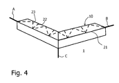
- FIG. 3 limit two abutting at the bend line 21 second separating lines 23 a triangular pull-out element D, whose base side along an outer edge of the edge protection profile 10 extends and whose tip is located on the fold line. If a triangular pull-out element D is removed from the edge protection profile 10 with the aid of the second separating lines 23, this can be guided around the corner of an article 1. This is in FIG. 4 shown. After sticking the dividing line free Profile lfte to the surfaces of the article 1 meeting at the edge C, the upstanding dividing upper halves of the edge protection profile 10 are folded back 90 ° along the crease line 21 so that they stick to the top surface of the article. In the corner in which the three edges A, B and C of the article 1 meet, said upper profile halves abut each other without any gaps and without overlapping, since the theoretically existing overlapping surface was previously removed with the tear-out element D.
- the invention discloses an edge protection profile that signals and defuses danger spots during transport by protecting corners and longitudinal edges of products on transport paths and the inventory and prevents impact injuries. It is preferably designed as a self-adhesive edge protection with rear anti-slip adhesion for interior and exterior applications on, for example, materials, machines, vehicles, or mobile inventory.
- the self-adhesive edge protection profile allows for easy installation as it adheres permanently and securely to smooth, clean, dust-free, degreased surfaces, corners and edges.
Landscapes
- Engineering & Computer Science (AREA)
- Mechanical Engineering (AREA)
- Adhesive Tapes (AREA)
- Packaging Of Machine Parts And Wound Products (AREA)
Abstract
Description
- Die Erfindung betrifft ein Kantenschutzprofil zum Schutz der Ecken und Kanten von Möbeln, Werkstücken, Maschinen und dergleichen, insbesondere währe nd eines Transportes dieser Elemente.
- Aus der
DE 38 19 606 C2 ist ein Kantenschutzprofil bekannt, mit dem die Kanten von Gegenständen während einer transportbedingten Umreifung geschützt werden können. Um eine ausreichende Stabilität für den hohen Druck de s Umreifungsbandes gewährleisten zu können, ist das Kantenschutzprofil als starrer Winkel ausgebildet. Eine besondere Formgebung sorgt ferner dafür, dass am Profil vorhandene Klebestreifen bei einer Stapelung von Profilen nicht zu einer wechselseitigen Verklebung führen. - Vor diesem Hintergrund war es Aufgabe der vorliegenden Erfindung, einen Kantenschutz bereitzustellen, der sich besonders leicht bevorraten und in Verbindung mit Gegenständen verschiedener Geometrien einfach und kostensparend anwenden lässt.
- Diese Aufgabe wird durch ein Kantenschutzprofil mit den Merkmalen des Anspruchs 1 gelöst. Vorteilhafte Ausgestaltungen sind in den Unteransprüchen enthalten.
- Das erfindungsgemäße Kantenschutzprofil hat allgemein eine längliche Form mit einer Längsachse und enthält eine Schaumstoffschicht, welche den Gegenstand durch ihre elastischen Eigenschaften schützt. Weiterhin enthält das Kantenschutzprofil in der Schaumstoffschicht mindestens eine Trennlinie mit einer Materialschwächung, die als Abreißhilfe dient. Typischerweise ist eine Mehrzahl von Trennlinien vorhanden, welche hinsichtlich ihres Verlaufes und ihrer Realisierung gleich oder aber auch verschiedenartig ausgebildet sein können (vgl. unten erläuterte Ausführungsformen).
- Aufgrund der im Kantenschutzprofil vorgesehenen Trennlinie(n) ist es möglich, dieses Profil besonders einfach und beispielsweise ohne Zuhilfenahme von Werkzeug zu verwenden.
- Das Kantenschutzprofil enthält ferner vorzugsweise eine Kleberschicht, mit der es selbstklebend auf einem Gegenstand befestigt werden kann. Die Schaumstoffschicht ist dabei in der Regel mittelbar oder unmittelbar auf der Kleberschicht angeordnet.
- Bei einer bevorzugten Ausgestaltung weist das Kantenschutzprofil eine Knicklinie auf, welche in Richtung der Längsachse verläuft. Die Knicklinie soll ferner etwa in der Mitte des Profils liegen, d. h. in einem Bereich zwischen 30 % und 70 % der Profilbreite. Die Knicklinie kann insbesondere als eine Materialschwächung im Schaumstoffstreifen ausgebildet sein, beispielsweise durch einen ganz oder teilweise durch die Dicke der Schaumstoffschicht gehenden Einschnitt. Entlang der Knicklinie kann das Kantenschutzprofil abgeklappt werden, um sich dem Verlauf einer Gegenstandskante optimal anpassen zu können.
- Die Materialschwächungen der Trennlinien können auf verschiedene Weise realisiert werden, beispielsweise durch Zonen geringerer Materialdichte in der Schaumstoffschicht. Besonders bevorzugt ist es, wenn mindestens eine Trennlinie als eine Perforation ausgebildet ist, d. h. als ein durchgehender oder intermittierender Einschnitt bzw. eine Ausnehmung in der Schaumstoffschicht. Eine solche Perforation lässt sich in einem nachträglichen Bearbeitungsschritt einfach und mit nahezu jedem beliebigen geometrischen Verlauf erzeugen.
- Gemäß einer ersten bevorzugten Ausführungsform verläuft die mindestens eine Trennlinie im Wesentlichen senkrecht zur Längsachse des Kantenschutzprofils. Durch einen solchen senkrechten Verlauf kann das Kantenschutzprofil entlang dieser Trennlinie sauber auf eine passende Länge gekürzt werden. Die Trennlinie kann sich dabei über die gesamte Breite des Kantenschutzprofils erstrecken, oder aber vorzugsweise auch nur über einen Teil der Breite. Beispielsweise kann die Trennlinie nur von einem Rand des Kantenschutzprofils bis etwa zur Mitte bzw. - falls vorhanden - bis zur oben erwähnten Knicklinie verlaufen, so dass die restliche Breite des Profils mit unverminderter Stabilität ausgebildet ist. Ein sauberes Abreißen des Kantenschutzprofils ist in diesen Fällen dennoch möglich, da die Trennlinie einen definierten Anfang für einen Querriss vorgibt.
- Typischerweise sind von den vorstehend genannten, senkrecht zur Längsachse verlaufenden Trennlinien mehrere vorhanden, damit das Kantenschutzprofil je nach Bedarf an unterschiedlichen Stellen abgetrennt werden kann. Besonders bevorzugt ist es, wenn derartige Trennlinien einen axialen Abstand (d. h. einen Abstand gemessen in Richtung der Längsachse) von ca. 70 % bis ca. 200 % der Breite des Kantenschutzprofils haben. In diesem Falle besitzen sie eine ausreichend feine Rasterung, um an quasi jede Gegenstandsgeometrie angepasst werden zu können.
- Gemäß einer anderen Ausführungsform von Trennlinien können mehrere Trennlinien schräg zur Längsachse verlaufen und dabei dreieckige Ausreißelemente begrenzen. Insbesondere können derartige Trennlinien unter einem Winkel von ca. 45° relativ zur Längsachse stehen. Wie mit Hilfe der Figuren näher erläutert wird, hat die Ausbildung von dreieckigen Ausreißelementen den Vorteil, dass das Kantenschutzprofil durchgehend um Ecken eines Gegenstandes herum gelegt werden kann und dabei die aneinanderstoßenden Kanten an allen Flächen lückenlos und ohne störende Materialüberlappungen schützt.
- Die Dicke des Kantenschutzprofils richtet sich im Wesentlichen nach den Anforderungen der vorgesehenen Anwendung und liegt typischerweise in einem Bereich von 1 mm bis 10 mm.
- Weiterhin wird das Kantenschutzprofil, welches in der Regel flexibel ist, vorzugsweise in Rollenform konfektioniert, so dass es platzsparend in großen Längen zur Verfügung steht. Von derartigen Rollen kann es dann in passenden Größen abgetrennt werden, insbesondere unter Zuhilfenahme von Trennlinien der oben beschriebenen Art, so dass quasi kein Materialverschnitt entsteht.
- Die Schaumstoffschicht kann im Prinzip aus allen gängigen Schaumstoffarten bestehen und insbesondere einen Polyethylenschaum enthalten.
- Die Kleberschicht weist vorzugsweise einen Kleber auf, welcher sich nach Beendigung der Benutzung des Kantenschutzprofils rückstandslos vom beklebten Gegenstand entfernen lässt. Geeignete Kleberstoffe aus Acrylaten, Dispersionen, Kautschuk (Hotmelt-Verfahren), Bitumen oder Butylen sind beispielsweise bekannt von Wannenschutzbändern (Oberflächenschutz), Messeklebebändern, Abstandshaltern/Stapelscheiben im Fensterrahmenbau etc. Der Kleber ist vorzugsweise mit einer Trennschicht verankert, z. B. mit einem Gelege oder einer Folie.
- Im Folgenden wird die Erfindung mit Hilfe der schematischen Figuren beispielhaft näher erläutert. Dabei zeigt:
- Fig. 1
- eine Aufsicht auf einen Ausschnitt eines erfindungsgemäßen Kantenschutzprofils;
- Fig. 2
- einen Schnitt durch das Kantenschutzprofil von
Figur 1 entlang der Linie II-II; - Fig. 3
- die Entfernung eines dreieckigen Ausreißelementes aus dem Kantenschutzprofil;
- Fig. 4
- die Anbringung des gemäß
Figur 3 vorbereiteten Kantenschutzprofils an der Ecke eines Gegenstandes. - Das erfindungsgemäße Kantenschutzprofil 10 erstreckt sich "endlos" axial entlang einer Längsachse (x-Achse des eingezeichneten Koordinatensystems) und hat senkrecht zu dieser Achse eine Breite B von beispielsweise 60 mm. Wie aus dem vergrößerten und nicht maßstäblichen Querschnitt von
Figur 2 erkennbar ist, besteht das Kantenschutzprofil 10 im unteren Teil aus einer Kleberschicht 11, auf welcher eine Schaumstoffschicht 12 angeordnet ist. Die Dicke d beträgt typischerweise 2 bis 5 mm. - Etwa entlang der Mittellinie des Kantenschutzprofils 10, d. h. auf halber Breite B/2, ist eine Knicklinie 21 vorgesehen. Bei der dargestellten Ausführungsform ist diese Knicklinie als ein durch den Schaumstoffstreifen 12 gehender Schnitt ausgebildet. Der Schnitt kann dabei wie dargestellt bis auf die Kleberschicht 11 reichen oder auch nur teilweise durch die Schaumstoffschicht 12 gehen. Entlang der Knicklinie 21 kann das Kantenschutzprofil 10 beim Anbringen an der Kante eines Gegenstandes um beliebige Winkel geklappt werden.
- Ein besonderes Merkmal des Kantenschutzprofils 10 ist es, dass es Trennlinien 22, 23 aufweist. Im dargestellten Beispiel verlaufen diese Trennlinien dabei nur in einer Längshälfte des Kantenschutzprofils, d. h. von der Knicklinie 21 bis zu einem der Ränder. Ferner gibt es im Beispiel zwei sich in ihrer Verlaufsrichtung unterscheidende Arten von Trennlinien, nämlich:
- 1. Senkrecht zur Längsachse x verlaufende erste Trennlinien 22, entlang derer das Kantenschutzprofil 10 auf eine gewünschte Länge abgetrennt werden kann. Diese ersten Trennlinien befinden sich dabei in einem Abstand a, welcher typischerweise der Breite B des Profils entspricht.
- Zweite, schräg zur Längsachse verlaufende Trennlinien 23. Im dargestellten Beispiel haben diese zweiten Trennlinien 23 einen Winkel α von ca. 45° relativ zur Längsachse und entspringen an dem Schnittpunkt der ersten Trennlinien 22 mit der Knicklinie 21.
- Wie aus
Figur 3 erkennbar ist, begrenzen zwei an der Knicklinie 21 aneinanderstoßende zweite Trennlinien 23 ein dreieckiges Ausreißelement D, dessen Grundseite entlang einer Außenkante des Kantenschutzprofils 10 verläuft und dessen Spitze auf der Knicklinie liegt. Wenn mit Hilfe der zweiten Trennlinien 23 ein dreieckiges Ausreißelement D aus dem Kantenschutzprofil 10 entfernt wird, kann dieses um die Ecke eines Gegenstandes 1 geführt werden. Dies ist inFigur 4 gezeigt. Nach Ankleben der trennlinienfreien unteren Profilhä lfte an die an der Kante C zusammentreffenden Flächen des Gegenstandes 1 werden die hochstehenden, mit Trennlinien versehenen oberen Hälften des Kantenschutzprofils 10 entlang der Knicklinie 21 um 90° zurückgeschlagen, so dass sie auf der oberen Fläche des Gegenstandes festkleben. In der Ecke, in der die drei Kanten A, B und C des Gegenstandes 1 zusammentreffen, stoßen die genannten oberen Profilhälften dabei lückenlos und ohne Überlappungen aneinander, da die theoretisch bestehende Überlappungsfläche zuvor mit dem Ausreißelement D entfernt wurde. - Zusammenfassend offenbart die Erfindung ein Kantenschutzprofil, das Gefahrenstellen beim Transport signalisiert und entschärft, indem es Ecken und Längskanten von Produkten auf Transportwegen sowie das Inventar schützt und Stoßverletzungen verhindert. Es ist vorzugsweise ausgebildet als selbstklebender Kantenschutz mit rückseitiger Antirutschhaftung für Innen - und Außenanwendungen an beispielsweise Werkstoffen, Maschinen, Fahrzeugen, oder mobilem Inventar.
- Das Kantenschutzprofil hat vorzugsweise folgende Materialeigenschaften:
- das Schutzmaterial wird gebildet durch einen hochverdichteten, kratzfesten, alterungsbeständigen Polyethylenschaum;
- ein Klebeeffekt wird erzeugt mit hoher Klebekraft, wobei der Kleber rückstandslos entfernbar ist (beispielsweise von Holz, Kunststoff, Metall);
- Temperaturbeständigkeit von -40°C bis +90°C;
- Perforationen zum Abreißen;
- Möglichkeit individueller Zuschnitte durch Schneidbarkeit;
- Länge variabel, z. B. bis 150 Meter
- Das selbstklebende Kantenschutzprofil erlaubt eine einfache Montage, da es auf glatten und auf gereinigten, staubfreien, entfetteten Flächen, Ecken und Kanten dauerhaft und sicher haftet.
Claims (12)
- Kantenschutzprofil (10) mit einer Längsachse (x), enthaltend eine Schaumstoffschicht (12), in der mindestens eine Trennlinie (22, 23) mit einer Materialschwächung als Abreißhilfe vorgesehen ist.
- Kantenschutzprofil (10) nach Anspruch 1,
dadurch gekennzeichnet, dass es eine Kleberschicht (11) enthält. - Kantenschutzprofil (10) nach Anspruch 1 oder 2,
dadurch gekennzeichnet, dass es eine Knicklinie (21) enthält, die etwa in der Mitte des Profils in Richtung der Längsachse (x) verläuft. - Kantenschutzprofil (10) nach mindestens einem der Ansprüche 1 bis 3,
dadurch gekennzeichnet, dass die Trennlinie (22, 23) als Perforation in der Schaumstoffschicht (12) ausgebildet ist. - Kantenschutzprofil (10) nach Anspruch 4,
dadurch gekennzeichnet, dass die Trennlinie (22) senkrecht zur Längsachse (x) verläuft. - Kantenschutzprofil (10) nach Anspruch 4 oder 5,
dadurch gekennzeichnet, dass die Trennlinie (22) sich nicht über die gesamte Breite (B) des Kantenschutzprofils erstreckt. - Kantenschutzprofil (10) nach mindestens einem der Ansprüche 1 bis 6,
dadurch gekennzeichnet, dass mehrere derartige Trennlinien (22) vorgesehen sind in einem Abstand (a) entsprechend ca. 70 % bis ca. 200 % der Profilbreite (B). - Kantenschutzprofil (10) nach mindestens einem der Ansprüche 1 bis 7,
dadurch gekennzeichnet, dass mindestens zwei Trennlinien (23) schräg zur Längsachse (x) verlaufen und dreieckige Ausreißelemente (D) begrenzen. - Kantenschutzprofil (10) nach mindestens einem der Ansprüche 1 bis 8,
dadurch gekennzeichnet, dass es eine Dicke (d) von ca. 1 mm bis ca. 10 mm hat. - Kantenschutzprofil (10) nach mindestens einem der Ansprüche 1 bis 9,
dadurch gekennzeichnet, dass es auf einer Rolle konfektioniert ist. - Kantenschutzprofil (10) nach mindestens einem der Ansprüche 1 bis 10,
dadurch gekennzeichnet, dass die Schaumstoffschicht einen Polyethylenschaum enthält. - Kantenschutzprofil (10) nach mindestens einem der Ansprüche 2 bis 11,
dadurch gekennzeichnet, dass die Kleberschicht (11) einen rückstandslos entfernbaren Kleber enthält, der insbesondere mit einer Trenn schicht verankert sein kann.
Applications Claiming Priority (1)
| Application Number | Priority Date | Filing Date | Title |
|---|---|---|---|
| DE102008043996A DE102008043996A1 (de) | 2008-11-21 | 2008-11-21 | Kantenschutzprofil |
Publications (2)
| Publication Number | Publication Date |
|---|---|
| EP2189392A1 true EP2189392A1 (de) | 2010-05-26 |
| EP2189392B1 EP2189392B1 (de) | 2012-04-18 |
Family
ID=41582151
Family Applications (1)
| Application Number | Title | Priority Date | Filing Date |
|---|---|---|---|
| EP09176639A Active EP2189392B1 (de) | 2008-11-21 | 2009-11-20 | Kantenschutzprofil |
Country Status (3)
| Country | Link |
|---|---|
| EP (1) | EP2189392B1 (de) |
| AT (1) | ATE554024T1 (de) |
| DE (1) | DE102008043996A1 (de) |
Cited By (1)
| Publication number | Priority date | Publication date | Assignee | Title |
|---|---|---|---|---|
| WO2013088016A1 (fr) * | 2011-12-16 | 2013-06-20 | Peugeot Citroen Automobiles Sa | Element de protection permettant le stockage, la manutention et le transport d'element vitre pour vehicule automobile tel qu'un pare-brise, une lunette arriere |
Citations (8)
| Publication number | Priority date | Publication date | Assignee | Title |
|---|---|---|---|---|
| DE7817861U1 (de) * | 1978-06-14 | 1978-09-28 | Siemens Ag | Verpackungselement |
| DE3819606C2 (de) | 1987-06-13 | 1989-08-31 | Signode System Gmbh, 4220 Dinslaken, De | |
| EP0443506A1 (de) | 1990-02-23 | 1991-08-28 | Kurt Dr. Heiniger | Kantenschutz |
| US5772037A (en) * | 1995-11-15 | 1998-06-30 | Hurley; Richard D. | Shipping protector |
| US5777037A (en) | 1995-01-17 | 1998-07-07 | Kanegafuchi Kagaku Kogyo Kabushiki Kaisha | Process for producing isobutylene polymer |
| GB2321032A (en) | 1996-09-06 | 1998-07-15 | Itw Ltd | Edge protector |
| US20030038054A1 (en) * | 2001-08-22 | 2003-02-27 | Hurley Richard B. | Shipping protector |
| US20080196315A1 (en) | 2006-12-01 | 2008-08-21 | Brisbois Michael B | Door edge protectors for use in conjunction with a door protective cover |
-
2008
- 2008-11-21 DE DE102008043996A patent/DE102008043996A1/de not_active Withdrawn
-
2009
- 2009-11-20 EP EP09176639A patent/EP2189392B1/de active Active
- 2009-11-20 AT AT09176639T patent/ATE554024T1/de active
Patent Citations (8)
| Publication number | Priority date | Publication date | Assignee | Title |
|---|---|---|---|---|
| DE7817861U1 (de) * | 1978-06-14 | 1978-09-28 | Siemens Ag | Verpackungselement |
| DE3819606C2 (de) | 1987-06-13 | 1989-08-31 | Signode System Gmbh, 4220 Dinslaken, De | |
| EP0443506A1 (de) | 1990-02-23 | 1991-08-28 | Kurt Dr. Heiniger | Kantenschutz |
| US5777037A (en) | 1995-01-17 | 1998-07-07 | Kanegafuchi Kagaku Kogyo Kabushiki Kaisha | Process for producing isobutylene polymer |
| US5772037A (en) * | 1995-11-15 | 1998-06-30 | Hurley; Richard D. | Shipping protector |
| GB2321032A (en) | 1996-09-06 | 1998-07-15 | Itw Ltd | Edge protector |
| US20030038054A1 (en) * | 2001-08-22 | 2003-02-27 | Hurley Richard B. | Shipping protector |
| US20080196315A1 (en) | 2006-12-01 | 2008-08-21 | Brisbois Michael B | Door edge protectors for use in conjunction with a door protective cover |
Cited By (4)
| Publication number | Priority date | Publication date | Assignee | Title |
|---|---|---|---|---|
| WO2013088016A1 (fr) * | 2011-12-16 | 2013-06-20 | Peugeot Citroen Automobiles Sa | Element de protection permettant le stockage, la manutention et le transport d'element vitre pour vehicule automobile tel qu'un pare-brise, une lunette arriere |
| FR2984289A1 (fr) * | 2011-12-16 | 2013-06-21 | Peugeot Citroen Automobiles Sa | Element de protection permettant le stockage, la manutention et le transport d'element vitre pour vehicule automobile tel qu'un pare-brise, une lunette arriere |
| CN104114466A (zh) * | 2011-12-16 | 2014-10-22 | 标致·雪铁龙汽车公司 | 用于如挡风玻璃或后窗的汽车玻璃元件的存储、装卸以及运输的保护元件 |
| CN104114466B (zh) * | 2011-12-16 | 2017-02-01 | 标致·雪铁龙汽车公司 | 用于如挡风玻璃或后窗的汽车玻璃元件的存储、装卸以及运输的保护元件 |
Also Published As
| Publication number | Publication date |
|---|---|
| DE102008043996A1 (de) | 2010-05-27 |
| EP2189392B1 (de) | 2012-04-18 |
| ATE554024T1 (de) | 2012-05-15 |
Similar Documents
| Publication | Publication Date | Title |
|---|---|---|
| EP2138664B1 (de) | Vorkomprimiertes Dichtband | |
| EP1813659B1 (de) | Verwendung eines Weiterreißfesten Klebebands | |
| EP1832691A1 (de) | Stützleiste für eine Verbundplatte | |
| WO2017157726A1 (de) | Profilleistenanordnung | |
| DE102005056439B4 (de) | Profilleiste zur Verwendung im Innenausbau sowie Bausatz einschließlich einer solchen Profilleiste | |
| EP3453806B2 (de) | Dichtelement | |
| EP3448702A1 (de) | Gerüstband mit verstärkungsmittel | |
| EP2189392B1 (de) | Kantenschutzprofil | |
| DE102008038473A1 (de) | Selbstklebend ausgerüsteter Streifen für den Transportschutz | |
| EP4124449B1 (de) | Etikett, etikettenband und verfahren zum herstellen von etiketten | |
| DE102004064030B4 (de) | Selbstklebend ausgerüsteter Streifen für den Transportschutz | |
| DE202022100548U1 (de) | Verpackungsmaterial in Form einer Sandwichplatte mit Wabenkern | |
| DE102022115248B4 (de) | Abdeckband | |
| EP4377218B1 (de) | Aufreissstreifen für eine verpackung, verfahren zum herstellen eines aufreissstreifens und verpackung | |
| EP2639182A1 (de) | Verfahren zum Herstellen einer Verpackung und Verpackung | |
| DE102012111470A1 (de) | Schaumstoffband | |
| DE102005015695B4 (de) | Aufkleber, Bandmaterial und Bandmaterialrolle zu seiner Herstellung sowie Verfahren zum Stapeln mehrerer Platten und Stapel mehrerer Platten | |
| DE102023134626A1 (de) | Verpackung und Verfahren zum Herstellen einer Verpackung | |
| DE102011118466B4 (de) | Flächenzuschnitt zum Ausbilden einer Lagesicherung, Verwendung und Verfahren zum Herstellen eines Flächenzuschnitts | |
| EP4265537A1 (de) | Papierschlauchbeutel und verfahren zu dessen herstellung | |
| DE102012209658A1 (de) | Verpackungsfolienlaminat mit integriertem Klebeband | |
| EP3113948A1 (de) | Folienmaterial zur herstellung einer verpackung | |
| EP1557450A1 (de) | Klebeband | |
| DE202004021106U1 (de) | Selbstklebend ausgerüsteter Streifen für den Transportschutz | |
| EP2900480A1 (de) | Anordnung umfassend einen plattenförmigen träger und ein darauf angeordnetes flächiges material |
Legal Events
| Date | Code | Title | Description |
|---|---|---|---|
| PUAI | Public reference made under article 153(3) epc to a published international application that has entered the european phase |
Free format text: ORIGINAL CODE: 0009012 |
|
| AK | Designated contracting states |
Kind code of ref document: A1 Designated state(s): AT BE BG CH CY CZ DE DK EE ES FI FR GB GR HR HU IE IS IT LI LT LU LV MC MK MT NL NO PL PT RO SE SI SK SM TR |
|
| AX | Request for extension of the european patent |
Extension state: AL BA RS |
|
| 17P | Request for examination filed |
Effective date: 20100708 |
|
| 17Q | First examination report despatched |
Effective date: 20100730 |
|
| REG | Reference to a national code |
Ref country code: DE Ref legal event code: R079 Ref document number: 502009003302 Country of ref document: DE Free format text: PREVIOUS MAIN CLASS: B65D0081050000 Ipc: B65D0081020000 |
|
| GRAP | Despatch of communication of intention to grant a patent |
Free format text: ORIGINAL CODE: EPIDOSNIGR1 |
|
| RIC1 | Information provided on ipc code assigned before grant |
Ipc: B65D 81/02 20060101AFI20111111BHEP |
|
| RIN1 | Information on inventor provided before grant (corrected) |
Inventor name: HILLE, THOMAS |
|
| GRAS | Grant fee paid |
Free format text: ORIGINAL CODE: EPIDOSNIGR3 |
|
| GRAA | (expected) grant |
Free format text: ORIGINAL CODE: 0009210 |
|
| AK | Designated contracting states |
Kind code of ref document: B1 Designated state(s): AT BE BG CH CY CZ DE DK EE ES FI FR GB GR HR HU IE IS IT LI LT LU LV MC MK MT NL NO PL PT RO SE SI SK SM TR |
|
| REG | Reference to a national code |
Ref country code: GB Ref legal event code: FG4D Free format text: NOT ENGLISH |
|
| REG | Reference to a national code |
Ref country code: CH Ref legal event code: EP |
|
| REG | Reference to a national code |
Ref country code: IE Ref legal event code: FG4D Free format text: LANGUAGE OF EP DOCUMENT: GERMAN |
|
| REG | Reference to a national code |
Ref country code: AT Ref legal event code: REF Ref document number: 554024 Country of ref document: AT Kind code of ref document: T Effective date: 20120515 |
|
| REG | Reference to a national code |
Ref country code: DE Ref legal event code: R096 Ref document number: 502009003302 Country of ref document: DE Effective date: 20120614 |
|
| REG | Reference to a national code |
Ref country code: NL Ref legal event code: VDEP Effective date: 20120418 |
|
| LTIE | Lt: invalidation of european patent or patent extension |
Effective date: 20120418 |
|
| PG25 | Lapsed in a contracting state [announced via postgrant information from national office to epo] |
Ref country code: NO Free format text: LAPSE BECAUSE OF FAILURE TO SUBMIT A TRANSLATION OF THE DESCRIPTION OR TO PAY THE FEE WITHIN THE PRESCRIBED TIME-LIMIT Effective date: 20120718 Ref country code: FI Free format text: LAPSE BECAUSE OF FAILURE TO SUBMIT A TRANSLATION OF THE DESCRIPTION OR TO PAY THE FEE WITHIN THE PRESCRIBED TIME-LIMIT Effective date: 20120418 Ref country code: IS Free format text: LAPSE BECAUSE OF FAILURE TO SUBMIT A TRANSLATION OF THE DESCRIPTION OR TO PAY THE FEE WITHIN THE PRESCRIBED TIME-LIMIT Effective date: 20120818 Ref country code: SE Free format text: LAPSE BECAUSE OF FAILURE TO SUBMIT A TRANSLATION OF THE DESCRIPTION OR TO PAY THE FEE WITHIN THE PRESCRIBED TIME-LIMIT Effective date: 20120418 Ref country code: PL Free format text: LAPSE BECAUSE OF FAILURE TO SUBMIT A TRANSLATION OF THE DESCRIPTION OR TO PAY THE FEE WITHIN THE PRESCRIBED TIME-LIMIT Effective date: 20120418 Ref country code: CY Free format text: LAPSE BECAUSE OF FAILURE TO SUBMIT A TRANSLATION OF THE DESCRIPTION OR TO PAY THE FEE WITHIN THE PRESCRIBED TIME-LIMIT Effective date: 20120418 Ref country code: LT Free format text: LAPSE BECAUSE OF FAILURE TO SUBMIT A TRANSLATION OF THE DESCRIPTION OR TO PAY THE FEE WITHIN THE PRESCRIBED TIME-LIMIT Effective date: 20120418 |
|
| PG25 | Lapsed in a contracting state [announced via postgrant information from national office to epo] |
Ref country code: GR Free format text: LAPSE BECAUSE OF FAILURE TO SUBMIT A TRANSLATION OF THE DESCRIPTION OR TO PAY THE FEE WITHIN THE PRESCRIBED TIME-LIMIT Effective date: 20120719 Ref country code: HR Free format text: LAPSE BECAUSE OF FAILURE TO SUBMIT A TRANSLATION OF THE DESCRIPTION OR TO PAY THE FEE WITHIN THE PRESCRIBED TIME-LIMIT Effective date: 20120418 Ref country code: LV Free format text: LAPSE BECAUSE OF FAILURE TO SUBMIT A TRANSLATION OF THE DESCRIPTION OR TO PAY THE FEE WITHIN THE PRESCRIBED TIME-LIMIT Effective date: 20120418 Ref country code: SI Free format text: LAPSE BECAUSE OF FAILURE TO SUBMIT A TRANSLATION OF THE DESCRIPTION OR TO PAY THE FEE WITHIN THE PRESCRIBED TIME-LIMIT Effective date: 20120418 Ref country code: PT Free format text: LAPSE BECAUSE OF FAILURE TO SUBMIT A TRANSLATION OF THE DESCRIPTION OR TO PAY THE FEE WITHIN THE PRESCRIBED TIME-LIMIT Effective date: 20120820 |
|
| PG25 | Lapsed in a contracting state [announced via postgrant information from national office to epo] |
Ref country code: NL Free format text: LAPSE BECAUSE OF FAILURE TO SUBMIT A TRANSLATION OF THE DESCRIPTION OR TO PAY THE FEE WITHIN THE PRESCRIBED TIME-LIMIT Effective date: 20120418 Ref country code: DK Free format text: LAPSE BECAUSE OF FAILURE TO SUBMIT A TRANSLATION OF THE DESCRIPTION OR TO PAY THE FEE WITHIN THE PRESCRIBED TIME-LIMIT Effective date: 20120418 Ref country code: SK Free format text: LAPSE BECAUSE OF FAILURE TO SUBMIT A TRANSLATION OF THE DESCRIPTION OR TO PAY THE FEE WITHIN THE PRESCRIBED TIME-LIMIT Effective date: 20120418 Ref country code: RO Free format text: LAPSE BECAUSE OF FAILURE TO SUBMIT A TRANSLATION OF THE DESCRIPTION OR TO PAY THE FEE WITHIN THE PRESCRIBED TIME-LIMIT Effective date: 20120418 Ref country code: CZ Free format text: LAPSE BECAUSE OF FAILURE TO SUBMIT A TRANSLATION OF THE DESCRIPTION OR TO PAY THE FEE WITHIN THE PRESCRIBED TIME-LIMIT Effective date: 20120418 Ref country code: EE Free format text: LAPSE BECAUSE OF FAILURE TO SUBMIT A TRANSLATION OF THE DESCRIPTION OR TO PAY THE FEE WITHIN THE PRESCRIBED TIME-LIMIT Effective date: 20120418 |
|
| PLBE | No opposition filed within time limit |
Free format text: ORIGINAL CODE: 0009261 |
|
| STAA | Information on the status of an ep patent application or granted ep patent |
Free format text: STATUS: NO OPPOSITION FILED WITHIN TIME LIMIT |
|
| PG25 | Lapsed in a contracting state [announced via postgrant information from national office to epo] |
Ref country code: IT Free format text: LAPSE BECAUSE OF FAILURE TO SUBMIT A TRANSLATION OF THE DESCRIPTION OR TO PAY THE FEE WITHIN THE PRESCRIBED TIME-LIMIT Effective date: 20120418 |
|
| PGFP | Annual fee paid to national office [announced via postgrant information from national office to epo] |
Ref country code: BE Payment date: 20121129 Year of fee payment: 4 |
|
| 26N | No opposition filed |
Effective date: 20130121 |
|
| PG25 | Lapsed in a contracting state [announced via postgrant information from national office to epo] |
Ref country code: ES Free format text: LAPSE BECAUSE OF FAILURE TO SUBMIT A TRANSLATION OF THE DESCRIPTION OR TO PAY THE FEE WITHIN THE PRESCRIBED TIME-LIMIT Effective date: 20120729 |
|
| REG | Reference to a national code |
Ref country code: DE Ref legal event code: R097 Ref document number: 502009003302 Country of ref document: DE Effective date: 20130121 |
|
| PG25 | Lapsed in a contracting state [announced via postgrant information from national office to epo] |
Ref country code: BG Free format text: LAPSE BECAUSE OF FAILURE TO SUBMIT A TRANSLATION OF THE DESCRIPTION OR TO PAY THE FEE WITHIN THE PRESCRIBED TIME-LIMIT Effective date: 20120718 |
|
| REG | Reference to a national code |
Ref country code: IE Ref legal event code: MM4A |
|
| REG | Reference to a national code |
Ref country code: FR Ref legal event code: ST Effective date: 20130731 |
|
| PG25 | Lapsed in a contracting state [announced via postgrant information from national office to epo] |
Ref country code: IE Free format text: LAPSE BECAUSE OF NON-PAYMENT OF DUE FEES Effective date: 20121120 |
|
| PG25 | Lapsed in a contracting state [announced via postgrant information from national office to epo] |
Ref country code: MT Free format text: LAPSE BECAUSE OF FAILURE TO SUBMIT A TRANSLATION OF THE DESCRIPTION OR TO PAY THE FEE WITHIN THE PRESCRIBED TIME-LIMIT Effective date: 20120418 Ref country code: FR Free format text: LAPSE BECAUSE OF NON-PAYMENT OF DUE FEES Effective date: 20121130 |
|
| PG25 | Lapsed in a contracting state [announced via postgrant information from national office to epo] |
Ref country code: TR Free format text: LAPSE BECAUSE OF FAILURE TO SUBMIT A TRANSLATION OF THE DESCRIPTION OR TO PAY THE FEE WITHIN THE PRESCRIBED TIME-LIMIT Effective date: 20120418 Ref country code: MC Free format text: LAPSE BECAUSE OF NON-PAYMENT OF DUE FEES Effective date: 20121130 |
|
| PG25 | Lapsed in a contracting state [announced via postgrant information from national office to epo] |
Ref country code: SM Free format text: LAPSE BECAUSE OF FAILURE TO SUBMIT A TRANSLATION OF THE DESCRIPTION OR TO PAY THE FEE WITHIN THE PRESCRIBED TIME-LIMIT Effective date: 20120418 Ref country code: LU Free format text: LAPSE BECAUSE OF NON-PAYMENT OF DUE FEES Effective date: 20121120 |
|
| BERE | Be: lapsed |
Owner name: HYDROPHON KUNSTSTOFFTECHNIK G.M.B.H. Effective date: 20131130 |
|
| GBPC | Gb: european patent ceased through non-payment of renewal fee |
Effective date: 20131120 |
|
| PG25 | Lapsed in a contracting state [announced via postgrant information from national office to epo] |
Ref country code: HU Free format text: LAPSE BECAUSE OF FAILURE TO SUBMIT A TRANSLATION OF THE DESCRIPTION OR TO PAY THE FEE WITHIN THE PRESCRIBED TIME-LIMIT Effective date: 20091120 |
|
| PG25 | Lapsed in a contracting state [announced via postgrant information from national office to epo] |
Ref country code: BE Free format text: LAPSE BECAUSE OF NON-PAYMENT OF DUE FEES Effective date: 20131130 |
|
| PG25 | Lapsed in a contracting state [announced via postgrant information from national office to epo] |
Ref country code: GB Free format text: LAPSE BECAUSE OF NON-PAYMENT OF DUE FEES Effective date: 20131120 |
|
| PG25 | Lapsed in a contracting state [announced via postgrant information from national office to epo] |
Ref country code: MK Free format text: LAPSE BECAUSE OF FAILURE TO SUBMIT A TRANSLATION OF THE DESCRIPTION OR TO PAY THE FEE WITHIN THE PRESCRIBED TIME-LIMIT Effective date: 20120418 |
|
| PGFP | Annual fee paid to national office [announced via postgrant information from national office to epo] |
Ref country code: CH Payment date: 20151123 Year of fee payment: 7 |
|
| PGFP | Annual fee paid to national office [announced via postgrant information from national office to epo] |
Ref country code: AT Payment date: 20151120 Year of fee payment: 7 |
|
| REG | Reference to a national code |
Ref country code: CH Ref legal event code: PL |
|
| REG | Reference to a national code |
Ref country code: AT Ref legal event code: MM01 Ref document number: 554024 Country of ref document: AT Kind code of ref document: T Effective date: 20161120 |
|
| PG25 | Lapsed in a contracting state [announced via postgrant information from national office to epo] |
Ref country code: CH Free format text: LAPSE BECAUSE OF NON-PAYMENT OF DUE FEES Effective date: 20161130 Ref country code: LI Free format text: LAPSE BECAUSE OF NON-PAYMENT OF DUE FEES Effective date: 20161130 |
|
| PG25 | Lapsed in a contracting state [announced via postgrant information from national office to epo] |
Ref country code: AT Free format text: LAPSE BECAUSE OF NON-PAYMENT OF DUE FEES Effective date: 20161120 |
|
| PGFP | Annual fee paid to national office [announced via postgrant information from national office to epo] |
Ref country code: DE Payment date: 20251130 Year of fee payment: 17 |