EP2189405A1 - Vorrichtung und Verfahren zur Abgabe einer verformbaren Materialbahn - Google Patents
Vorrichtung und Verfahren zur Abgabe einer verformbaren Materialbahn Download PDFInfo
- Publication number
- EP2189405A1 EP2189405A1 EP09176695A EP09176695A EP2189405A1 EP 2189405 A1 EP2189405 A1 EP 2189405A1 EP 09176695 A EP09176695 A EP 09176695A EP 09176695 A EP09176695 A EP 09176695A EP 2189405 A1 EP2189405 A1 EP 2189405A1
- Authority
- EP
- European Patent Office
- Prior art keywords
- web
- transport element
- housing
- guide
- transport
- Prior art date
- Legal status (The legal status is an assumption and is not a legal conclusion. Google has not performed a legal analysis and makes no representation as to the accuracy of the status listed.)
- Withdrawn
Links
Images

Classifications
-
- B—PERFORMING OPERATIONS; TRANSPORTING
- B65—CONVEYING; PACKING; STORING; HANDLING THIN OR FILAMENTARY MATERIAL
- B65H—HANDLING THIN OR FILAMENTARY MATERIAL, e.g. SHEETS, WEBS, CABLES
- B65H20/00—Advancing webs
- B65H20/02—Advancing webs by friction roller
-
- B—PERFORMING OPERATIONS; TRANSPORTING
- B31—MAKING ARTICLES OF PAPER, CARDBOARD OR MATERIAL WORKED IN A MANNER ANALOGOUS TO PAPER; WORKING PAPER, CARDBOARD OR MATERIAL WORKED IN A MANNER ANALOGOUS TO PAPER
- B31D—MAKING ARTICLES OF PAPER, CARDBOARD OR MATERIAL WORKED IN A MANNER ANALOGOUS TO PAPER, NOT PROVIDED FOR IN SUBCLASSES B31B OR B31C
- B31D5/00—Multiple-step processes for making three-dimensional [3D] articles
- B31D5/0039—Multiple-step processes for making three-dimensional [3D] articles for making dunnage or cushion pads
-
- B—PERFORMING OPERATIONS; TRANSPORTING
- B65—CONVEYING; PACKING; STORING; HANDLING THIN OR FILAMENTARY MATERIAL
- B65H—HANDLING THIN OR FILAMENTARY MATERIAL, e.g. SHEETS, WEBS, CABLES
- B65H16/00—Unwinding, paying-out webs
- B65H16/005—Dispensers, i.e. machines for unwinding only parts of web roll
-
- B—PERFORMING OPERATIONS; TRANSPORTING
- B65—CONVEYING; PACKING; STORING; HANDLING THIN OR FILAMENTARY MATERIAL
- B65H—HANDLING THIN OR FILAMENTARY MATERIAL, e.g. SHEETS, WEBS, CABLES
- B65H20/00—Advancing webs
- B65H20/26—Mechanisms for advancing webs to or from the inside of web rolls
-
- B—PERFORMING OPERATIONS; TRANSPORTING
- B31—MAKING ARTICLES OF PAPER, CARDBOARD OR MATERIAL WORKED IN A MANNER ANALOGOUS TO PAPER; WORKING PAPER, CARDBOARD OR MATERIAL WORKED IN A MANNER ANALOGOUS TO PAPER
- B31D—MAKING ARTICLES OF PAPER, CARDBOARD OR MATERIAL WORKED IN A MANNER ANALOGOUS TO PAPER, NOT PROVIDED FOR IN SUBCLASSES B31B OR B31C
- B31D2205/00—Multiple-step processes for making three-dimensional articles
- B31D2205/0005—Multiple-step processes for making three-dimensional articles for making dunnage or cushion pads
- B31D2205/0011—Multiple-step processes for making three-dimensional articles for making dunnage or cushion pads including particular additional operations
- B31D2205/0017—Providing stock material in a particular form
- B31D2205/0023—Providing stock material in a particular form as web from a roll
- B31D2205/0029—Providing stock material in a particular form as web from a roll unwound from inside
-
- B—PERFORMING OPERATIONS; TRANSPORTING
- B65—CONVEYING; PACKING; STORING; HANDLING THIN OR FILAMENTARY MATERIAL
- B65H—HANDLING THIN OR FILAMENTARY MATERIAL, e.g. SHEETS, WEBS, CABLES
- B65H2301/00—Handling processes for sheets or webs
- B65H2301/30—Orientation, displacement, position of the handled material
- B65H2301/32—Orientation of handled material
- B65H2301/325—Orientation of handled material of roll of material
- B65H2301/3251—Orientation of handled material of roll of material vertical axis
-
- B—PERFORMING OPERATIONS; TRANSPORTING
- B65—CONVEYING; PACKING; STORING; HANDLING THIN OR FILAMENTARY MATERIAL
- B65H—HANDLING THIN OR FILAMENTARY MATERIAL, e.g. SHEETS, WEBS, CABLES
- B65H2401/00—Materials used for the handling apparatus or parts thereof; Properties thereof
- B65H2401/20—Physical properties, e.g. lubricity
- B65H2401/22—Optical properties, e.g. opacity or transparency
-
- B—PERFORMING OPERATIONS; TRANSPORTING
- B65—CONVEYING; PACKING; STORING; HANDLING THIN OR FILAMENTARY MATERIAL
- B65H—HANDLING THIN OR FILAMENTARY MATERIAL, e.g. SHEETS, WEBS, CABLES
- B65H2404/00—Parts for transporting or guiding the handled material
- B65H2404/10—Rollers
- B65H2404/14—Roller pairs
- B65H2404/144—Roller pairs with relative movement of the rollers to / from each other
-
- B—PERFORMING OPERATIONS; TRANSPORTING
- B65—CONVEYING; PACKING; STORING; HANDLING THIN OR FILAMENTARY MATERIAL
- B65H—HANDLING THIN OR FILAMENTARY MATERIAL, e.g. SHEETS, WEBS, CABLES
- B65H2404/00—Parts for transporting or guiding the handled material
- B65H2404/10—Rollers
- B65H2404/16—Details of driving
- B65H2404/162—Details of driving containing, enclosing own driving means
Definitions
- the invention relates to an apparatus for dispensing a deformable web.
- Such an apparatus is known per se from the prior art, see for instance WO2005/102677 .
- the web creased by this apparatus is for instance used as filler, for instance a cushion material, to fill up packages.
- Disadvantages of known apparatuses are that they are relatively slow, sizeable, noisy and susceptible to trouble.
- the present invention contemplates an improved apparatus.
- the apparatus is characterized by the features of claim 1.
- the apparatus for dispensing a deformable web advantageously comprises a preferably cylinder-shaped transport element rotatable under the influence of a drive, and a web guide disposed opposite thereto, the transport element and the web guide being arranged to cooperate, for the purpose of transport and deformation of the web.
- the drive is completely integrated into the transport element.
- a web can be dispensed, and thereby deformed, for instance folded and/or creased.
- the present apparatus is relatively durable, and can be manufactured from few components. The number of components moving during use can be limited to a minimum.
- an aspect of the invention provides for use of a cylinder-shaped transport element. With such a shape, high dispensing speeds can be achieved, in a reliable manner, in particular in that the cylinder-shaped transport element can engage the web over a relatively large contact surface. Particularly advantageous is an embodiment where both a cylinder-shaped transport element and a drive integrated therein are provided.
- the drive can for instance comprise a tube motor.
- an outside of the transport element may be provided with friction enhancing projections.
- the projections for instance relatively blunt studs
- the projections can ensure high web throughput speeds, and moreover bring about web deformation (for instance folding and/or crumpling) during web feed-through.
- At least the outside of the transport element is preferably manufactured from friction enhancing material, in particular resilient friction enhancing material, in particular rubber.
- the apparatus is provided with a housing, arranged to hold a web to be dispensed.
- the housing is then preferably provided with an inner space which can be substantially closed off from an environment, arranged to fully enclose a web to be dispensed.
- the housing can properly protect the web to be dispensed from unwanted ambient influences, such as moisture or manipulation, and moreover afford safety to bystanders during use of the apparatus.
- the housing is provided with at least one transparent wall, via which wall for instance the contents (web to be dispensed) are visible for the purpose of inspection.
- a particularly advantageous embodiment of the apparatus is provided with a number of walls (for instance a front wall, rear wall, and sidewalls extending therebetween), which walls are provided with wall parts obliquely converging towards each other, extending to a web dispensing area.
- inner sides of these wall parts may already provide for a web guidance, and/or a web deformation.
- a stable apparatus can be obtained, having a relatively high stiffness and strength, utilizing relatively lightweight wall materials.
- the walls mentioned can for instance be made of plastic, Plexiglas, glass, or the like, for instance from plastic plate material.
- the invention is not limited to these materials; other options include use of walls manufactured, for instance, from metal, an alloy, wood and/or the like.
- a particularly compact, relatively low-noise apparatus is obtained when the housing is provided with an upper edge which surrounds a web passage, the housing being preferably provided with a cover structure which holds the transport element and the web guide, and preferably the drive, at a level above the upper edge.
- the transport element and the drive during operation are situated in or under the cover structure, at least under an upper wall of the apparatus defined by the cover structure.
- a preferred embodiment comprises an apparatus designed to draw a web from a stationary web roll and dispense it.
- the apparatus may in particular be provided with a support to support a side of the web roll.
- Such a support can moreover afford stability to the apparatus, whether or not utilizing a web roll mass carried by the support.
- a weight of the web roll may for instance be active centrally on the apparatus during use.
- the present invention furthermore concerns an advantageous method for dispensing a web, utilizing an apparatus according to the invention, wherein a web roll and the apparatus are disposed stationarily with respect to each other, wherein a web end of the stationary web roll is passed along the transport element and the web guide, wherein the drive imparts rotation to the transport element for dispensing the web.
- a roll holder provided with the web roll is provided, with the roll holder being opened and brought into a position cooperating with the apparatus, to load the apparatus with the web roll.
- the present invention furthermore concerns an advantageous method for dispensing a web, for instance utilizing an apparatus according to the invention, wherein a rotating cylinder-shaped web transport element and a stationary web guide cooperate with each other to deform, and further discharge, a web passed between them.
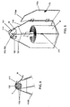
- Fig. 1 shows an example of an apparatus 1 for dispensing a deformable web.
- the web W to be deformed in the example is manufactured from paper, and is creasable and foldable.
- the dispensed web can for instance have utility as dunnage, for instance a cushion material, to fill up packages.
- the apparatus 1 is provided with a housing 10, arranged to hold the web W to be dispensed.
- the present housing 10 is provided with an inner space which can be substantially closed off from an environment, arranged to fully enclose the web W to be dispensed, for instance to increase safety of use of the apparatus, and to protect the web W.
- the housing 10 can receive the web W in a rolled-up condition, as a paper roll R.
- the housing 10 is manufactured wholly from plastic, and preferably with substantially closed walls 10a, 10b, 10c, 10d, 10e having a thickness of less than 1 cm, so that a relatively lightweight apparatus 1 can be obtained.
- a space that during use is substantially closed off (by a housing 10) from an environment, to hold paper web W to be dispensed, the apparatus 1 can be active in a relatively low-noise manner, at high web dispensing speeds.
- the housing 10 may be provided with a front wall 10a, rear wall 10b, and opposite sidewalls 10c, 10d extending therebetween.
- the walls 10a, 10b, 10c, 10d in this case are provided with tapering wall parts 10at, 10bt, 10ct, 10dt extending towards an upper edge TR situated at a web dispensing area.
- the upper edge TR of the housing 10 (comprising upper edges of the tapering wall parts) surrounds a web passage.
- the paper roll R during use extends between the walls 10a, 10b, 10c, 10d, on the bottom 10e and below the (horizontal) level of the tapering wall parts 10at, 10bt, 10ct, 10dt.
- the bottom 10e forms a support for supporting a side of the web roll R, in particular such that a centerline of the web roll R extends at right angles to a centerline of the transport element 5 already mentioned.
- web W during use is unwound from a radially inner part of the roll R (i.e. the roll R is unwound from the inside to the outside).
- a roll supporting face defined by the bottom 10e is for instance larger than a web passage defined by the apparatus, situated opposite that support 10e, near a transport element 5 to be further discussed hereinafter.
- the tapering wall parts 10at, 10bt, 10ct, 10dt provide a (truncated) pyramid-shaped top of the housing, whose (preferably smooth) inner side is configured to guide the paper web W from the roll R to transport element 5 and guide 11, via the passage surrounded by the upper edge R.
- This top of the housing can already pre-form, at least gather, the web W.
- the apparatus 1 can thus engage web W from rolls of different dimensions, allowing relatively high dispensing speeds to be achieved in a reliable manner, both during web unwinding from relatively central locations in the inner space and when web W is being pulled from locations close to the walls 10a, 10b, 10c, 10d out of the inner space.
- the housing 10 is provided with at least one transparent wall.
- Each of the walls 10a, 10b, 10c, 10d may for instance be of transparent design.
- one or more wall may for instance be lightproof.
- at least one of the walls, viz. the front wall 10a, inclusive of a respective tapering part 10at, is of transparent design.
- the housing 10 may be provided with a cover structure 51, 52, which holds a transport element 5 and a web guide 11 at a level above the upper edge of the housing 10.
- the transport element 5 and the drive 6 during operation are situated wholly in a space surrounded by the cover structure, under a top wall 52 of the apparatus, defined by the cover structure.
- the housing 10 is preferably provided with an access closable by a wall, in this example comprising an access closable by a pivotable front wall 10a (door).
- the front wall 10a is coupled to a sidewall 10d by hinges (see also Fig. 5 ).
- the figures show a closed position of the front wall 10a. In an opened, outwardly pivoted position thereof, the inner space surrounded by housing 10 is accessible, for instance to insert a web roll R, and to draw web W from the roll and bring it to the cover 51, 52, in order to be taken over by the transport element 5.
- the whole wall 10a hence inclusive of a respective tapering upper part 10at, forms a movable component to close the access (see also Fig. 5 ).
- the apparatus 1 may for instance be provided with a retaining device 71, 72 to keep the front wall 10a in a closed position.
- the retaining device is provided with a permanent magnet 71 (for instance arranged on a sidewall 10c) which engages a metal strip 72 (in this case arranged on the door 10a) in a closed position of the door.
- the apparatus 1 shown in Figs. 1-4 is of particularly compact and robust construction, and to this end is advantageously provided with a cylinder-shaped transport element 5 (having an outside of substantially circular cross section) rotatable under the influence of a drive, and a web guide 11 disposed opposite thereto.
- the apparatus is not provided with gears to deform the web.
- the apparatus provided with separate gears to transmit rotation of an external motor shaft to web transport means. This contributes to durability, reliability and a low noise level.
- the transport element 5 and the web guide 11 are arranged to cooperate, for the purpose of transport and deformation of the web W (laid along them).
- the drive 7 in this example is fully integrated into the transport element 5, and is preferably a tube motor 7, the transport element 5 being a (cylinder-shaped) tube 5 driven by that motor 7.
- the guide of the first example is a cylinder-shaped counter roller 11, rotatable about a respective axis. Rotation axes of this roller 11 and transport element 5 are parallel with respect to each other.
- the outside of the transport element 5 is preferably uninterrupted, closed, and preferably wholly manufactured from friction enhancing material, in particular resilient friction enhancing material, in particular rubber. In this way, the transport element 5 can provide for good grip on the paper.
- the outside of the counter roller 11 may also be provided with such friction enhancing material.
- the web guide 11 is movable from the web guide position moved to the transport element 5, shown in Figs. 2-4 , to a release position moved away from the transport element 5 (shown in Fig. 1 ), and vice versa.
- the present apparatus comprises a web dispensing head, in particular a cover structure 51, 52 as mentioned, provided with a first cover part 51, attached to the upper side of the housing 10, and a second cover part 52, which is movable (in particular pivotable) relative to the first cover part 52.
- One cover part in the example the first cover part 51 is provided with the drive 7 with transport element 5, and the other cover part (in the example the second cover part 52) is provided with the rotatable (itself nondriven) guide 11.
- the cover In a closed position of the cover 51, 52, the cover preferably constitutes a substantially closed covering of the top of the housing 10, and of the transport element with motor 5, 6 and rotatable guide 11 held by the cover 51, 52.
- the cover 51, 52 can provide for a good reduction of acoustic transmission, to control broadcast of noise coming from the apparatus.
- the apparatus may be provided on an inside thereof with sound-absorbing material, for instance acoustic foam or the like (not shown), to achieve further noise reduction.
- the cover parts 51, 52 may be provided on an inside thereof with for instance wall parts 51a, 52a, which - viewed in front view - partly overlap rearwardly situated rotatable components 5, 11.
- the latter wall parts 51a, 52a bound a web dispensing gap with the cover 51, 52 closed.
- Sidewalls, a top wall and rear wall of the cover 51, 52 are preferably wholly closed, with the cover closed.
- cover parts 51, 52 In the position of the cover parts 51, 52 when moved away from each other, guide 11 and transport element 5 are moved apart, such that web W can be passed between them (see Fig. 1 ). Thereupon, cover parts 51, 52 can be brought into the position moved towards each other, such that the web W is clamped between guide 11 and transport element 5, to be engaged by guide 11 and transport element 5 and to be discharged from the housing 10 at high speed.
- the apparatus 1 is provided with locking means, for instance releasable closing elements 53, to lock the cover parts 51, 52 in the position moved towards each other.
- locking means for instance releasable closing elements 53
- the apparatus for instance cover 51, 52
- spring means arranged to spring-mount the web guide 11, and in particular to push the guide 11 under the influence of spring force in the direction of the transport element 5 (i.e. in a radial direction of the guide 11).
- the spring suspension of the counter roller 11 can provide a particular pressure, to transport the paper W.
- the spring means 11 can bring about a proper web engagement between web guide 11 and driving tube 5, and also afford noise reduction.
- the present apparatus 1 during use can draw web W from a stationary web roll R, fold it and dispense it.
- the apparatus is provided with only one transport element 5, drivable by a drive 7, to transport and deform the web.
- the apparatus can dispense the web W at a speed of more than 100 meters per minute, in particular a speed of more than 150 meters per minute, more particularly a speed of at least 200 meters per minute.
- the apparatus 1 during use can dispense web W, with the web roll R and the apparatus 1 being disposed stationarily with respect to each other.
- a web end of the stationary web roll R (with cover 51, 52 open) is passed along the transport element 5 and the web guide 11.
- the drive 7 imparts rotation to the transport element 5 for dispensing the web W.
- Folded web W dispensed by the apparatus has for instance a tubular shape, provided with at least two longitudinal folds (see Figs. 1, 3 ).
- a web W dispensed over a particular length can be removed from a remaining web part, for instance be torn off, cut off or the like.
- the apparatus 1 can optionally be provided with tearing or cutting means (for instance a saw tooth strip) which may for instance be arranged on or near the head 51, 52.
- the example shown in Figs. 5-6 differs from the first example in that the web guide comprises a stationarily disposed guide element 111.
- the web guide comprises a stationarily disposed guide element 111.
- an outside of the transport element 105 and an inside of the web guide 111 extending opposite thereto bound a deformation zone, of a circular segment-shaped cross section (see Fig. 6 ).
- the second example is designed in particular to crease the web W. Also, this example can provide a fold in the web W, as represented in the figures.
- the rotatable transport element 105 is disposed on or near the upper end of the housing 110, and in particular connected, via the drive and two rigid coupling pieces 161, to a (in this case truncated pyramid-shaped) cover part 151 of the housing 110.
- the rotatable transport element 105 extends between an inside of the web guide 111 on one side and a web accommodation space defined by the housing on the other side.
- the web guide 111 comprises an integral component of the housing, and in particular is integrated with a rear wall 110B of the housing 110.
- an outside of the transport element 105 is provided with friction enhancing projections 106.
- the projections 106 preferably meet one or more of the following features, and more preferably each of the following features:
- the working of the second example comprises cooperation between the rotating cylinder-shaped web transport element 105 and a stationary web guide 11, to crease and further discharge the web W passed therebetween.
- the projections 106 preferably stud-shaped, bring about crumpling during transport, along with a proper engagement of a paper web W.
- This example too can achieve high web discharge speeds, and is reliable, compact, low-noise and durable.
Landscapes
- Advancing Webs (AREA)
- Unwinding Webs (AREA)
Applications Claiming Priority (1)
| Application Number | Priority Date | Filing Date | Title |
|---|---|---|---|
| NL2002241A NL2002241C2 (nl) | 2008-11-21 | 2008-11-21 | Inrichting en werkwijze voor het afgeven van een vervormbaar web. |
Publications (1)
| Publication Number | Publication Date |
|---|---|
| EP2189405A1 true EP2189405A1 (de) | 2010-05-26 |
Family
ID=40791161
Family Applications (1)
| Application Number | Title | Priority Date | Filing Date |
|---|---|---|---|
| EP09176695A Withdrawn EP2189405A1 (de) | 2008-11-21 | 2009-11-20 | Vorrichtung und Verfahren zur Abgabe einer verformbaren Materialbahn |
Country Status (3)
| Country | Link |
|---|---|
| US (1) | US20100127112A1 (de) |
| EP (1) | EP2189405A1 (de) |
| NL (1) | NL2002241C2 (de) |
Cited By (1)
| Publication number | Priority date | Publication date | Assignee | Title |
|---|---|---|---|---|
| WO2012027576A3 (en) * | 2010-08-26 | 2012-07-26 | Pregis Innovative Packaging, Inc. | Center-fed dunnage system |
Families Citing this family (10)
| Publication number | Priority date | Publication date | Assignee | Title |
|---|---|---|---|---|
| EP2655053B1 (de) | 2010-12-23 | 2017-03-22 | Pregis Innovative Packaging LLC | Mittig gespeistes packmaterialsystem und schneidvorrichtung |
| CA2849084C (en) | 2011-09-20 | 2018-07-03 | Pregis Innovative Packaging, Inc. | Tear-assist apparatus |
| US10940660B2 (en) * | 2015-08-03 | 2021-03-09 | Storopack Hans Reichenecker Gmbh | Device and method for manufacturing gas filled cushions from preconfigured film material |
| US10940659B2 (en) | 2017-05-11 | 2021-03-09 | Pregis Innovative Packaging Llc | Strap assembly on stock material units for a dunnage conversion machine |
| US11034121B2 (en) | 2017-05-11 | 2021-06-15 | Pregis Innovative Packaging Llc | Dunnage apparatus carton filler |
| US10926506B2 (en) | 2017-05-11 | 2021-02-23 | Pregis Innovative Packaging Llc | Fanfold supply cart |
| US11020930B2 (en) | 2017-05-11 | 2021-06-01 | Pregis Innovative Packaging Llc | Splice member on stock material units for a dunnage conversion machine |
| US11007746B2 (en) | 2017-05-11 | 2021-05-18 | Pregis Innovative Packaging Llc | Dunnage supply intake |
| DE102017114340A1 (de) | 2017-06-28 | 2019-01-03 | Storopack Hans Reichenecker Gmbh | Vorrichtung zum Bereitstellen von Polstermaterial für Verpackungszwecke |
| DE102018007549A1 (de) * | 2018-09-24 | 2020-03-26 | Sprick Gmbh Bielefelder Papier- Und Wellpappenwerke & Co. | Antriebsmechanismus für einen Verpackungsmaterial-Strangwickler, Verpackungsmaterial- Strangwickler, gewickeltes Verpackungsmaterial-Polster und Verfahren zum Herstellen desselben |
Citations (6)
| Publication number | Priority date | Publication date | Assignee | Title |
|---|---|---|---|---|
| US5553806A (en) * | 1994-05-19 | 1996-09-10 | Beloit Technologies, Inc. | Support or pressure roll for a paper roll winder |
| US20040026844A1 (en) * | 2002-06-02 | 2004-02-12 | Naoyuki Toriumi | Elastic member and paper feeding roller using same |
| US20050236096A1 (en) * | 2004-04-23 | 2005-10-27 | Joyner Kenny L | Method and apparatus for substantially lifting erasable marked images from a marking surface or the like |
| WO2005102677A1 (en) | 2004-03-26 | 2005-11-03 | Free-Flow Packaging International, Inc. | Machine and method for making paper dunnage |
| WO2006087511A1 (en) * | 2005-02-18 | 2006-08-24 | Easypack Limited | Method and apparatus for dispensing packaging; method and apparatus for guarding machinery |
| EP1852380A1 (de) * | 2006-05-02 | 2007-11-07 | Rex Products, Inc. | Motorisch angetriebener Klebepapierspender |
Family Cites Families (9)
| Publication number | Priority date | Publication date | Assignee | Title |
|---|---|---|---|---|
| US1178566A (en) * | 1915-12-10 | 1916-04-11 | William E Wright And Sons Company | Antitwisting device. |
| US2686018A (en) * | 1953-02-13 | 1954-08-10 | Int Harvester Co | Internal friction device |
| US2909341A (en) * | 1957-05-27 | 1959-10-20 | Lewis A Kingsley | Wire aligning and tensioning mechanism |
| US5118011A (en) * | 1990-12-05 | 1992-06-02 | Oatey Co. | Food roller dispenser |
| GB9412076D0 (en) * | 1994-06-16 | 1994-08-03 | Wyant And Company Limited | Paper towel dispenser for dispensing towelling from inside diameter of roll |
| US6695247B2 (en) * | 2001-10-10 | 2004-02-24 | Sca Hygiene Products Ab | Holder for a paper roll with axial dispensing of the paper in the roll |
| US6726142B2 (en) * | 2001-12-31 | 2004-04-27 | Kimberly-Clark Worldwide, Inc. | Twist controlling device, rotatable nip and axial feed system |
| GB0503383D0 (en) * | 2005-02-18 | 2005-03-23 | Easypack Ltd | Packaging and machinery |
| US7748659B2 (en) * | 2006-10-24 | 2010-07-06 | Lincoln Global, Inc. | Wire tensioning arrangement |
-
2008
- 2008-11-21 NL NL2002241A patent/NL2002241C2/nl not_active IP Right Cessation
-
2009
- 2009-11-20 US US12/623,287 patent/US20100127112A1/en not_active Abandoned
- 2009-11-20 EP EP09176695A patent/EP2189405A1/de not_active Withdrawn
Patent Citations (6)
| Publication number | Priority date | Publication date | Assignee | Title |
|---|---|---|---|---|
| US5553806A (en) * | 1994-05-19 | 1996-09-10 | Beloit Technologies, Inc. | Support or pressure roll for a paper roll winder |
| US20040026844A1 (en) * | 2002-06-02 | 2004-02-12 | Naoyuki Toriumi | Elastic member and paper feeding roller using same |
| WO2005102677A1 (en) | 2004-03-26 | 2005-11-03 | Free-Flow Packaging International, Inc. | Machine and method for making paper dunnage |
| US20050236096A1 (en) * | 2004-04-23 | 2005-10-27 | Joyner Kenny L | Method and apparatus for substantially lifting erasable marked images from a marking surface or the like |
| WO2006087511A1 (en) * | 2005-02-18 | 2006-08-24 | Easypack Limited | Method and apparatus for dispensing packaging; method and apparatus for guarding machinery |
| EP1852380A1 (de) * | 2006-05-02 | 2007-11-07 | Rex Products, Inc. | Motorisch angetriebener Klebepapierspender |
Cited By (1)
| Publication number | Priority date | Publication date | Assignee | Title |
|---|---|---|---|---|
| WO2012027576A3 (en) * | 2010-08-26 | 2012-07-26 | Pregis Innovative Packaging, Inc. | Center-fed dunnage system |
Also Published As
| Publication number | Publication date |
|---|---|
| US20100127112A1 (en) | 2010-05-27 |
| NL2002241C2 (nl) | 2010-05-25 |
Similar Documents
| Publication | Publication Date | Title |
|---|---|---|
| EP2189405A1 (de) | Vorrichtung und Verfahren zur Abgabe einer verformbaren Materialbahn | |
| AU2005339238B2 (en) | Dispenser loading arrangement and method of loading a dispenser | |
| CN110709233B (zh) | 垫料转换系统和扇状折叠库存材料供应推车 | |
| WO2003106121A1 (en) | Roll supporting slide cutter assembly | |
| US7424843B2 (en) | Wrapping paper storage device and dispenser | |
| US20210086466A1 (en) | Coiling device and cushion coiling system | |
| US7347395B2 (en) | Box for transportation and dispensing items to be used in garages | |
| WO2014145832A1 (en) | Dunnage supply daisy chain stabilizer | |
| US20090026306A1 (en) | Method and apparatus for dispensing packaging; method and apparatus for guarding machinery | |
| JP2018047370A (ja) | 自動ナプキンディスペンサ | |
| CN110612202B (zh) | 抗风的扇形折叠供应支撑件 | |
| CA2411645C (en) | Transportation and dispenser box made of cardboard and including a roll of items to be used in garages | |
| US20110041461A1 (en) | Packaging material dispenser | |
| US20070051770A1 (en) | Storage and dispensing device for materials on rolls | |
| KR102398900B1 (ko) | 핸드 랩핑기 | |
| JP5504116B2 (ja) | ロール形ウエットティッシュの供給器 | |
| WO2006087511A1 (en) | Method and apparatus for dispensing packaging; method and apparatus for guarding machinery | |
| US12137845B2 (en) | Box for dispensing pre-cut wiping material which can be unwound in a strip, and use of such a dispensing box | |
| KR102487592B1 (ko) | 전동식 필름 절단장치 | |
| KR102657041B1 (ko) | 친환경 종이 완충재용 인출 제동 장치 | |
| KR20230121392A (ko) | 테이프 디스펜서 | |
| US12420515B2 (en) | Fill material cutting systems for partially or fully cutting fill material | |
| CN201123773Y (zh) | 有断纸功能的筒状卫生纸盒 | |
| US20240010377A1 (en) | Machine and method | |
| EP2361529B1 (de) | Zusammenklappbarer Tapeziertisch |
Legal Events
| Date | Code | Title | Description |
|---|---|---|---|
| PUAI | Public reference made under article 153(3) epc to a published international application that has entered the european phase |
Free format text: ORIGINAL CODE: 0009012 |
|
| AK | Designated contracting states |
Kind code of ref document: A1 Designated state(s): AT BE BG CH CY CZ DE DK EE ES FI FR GB GR HR HU IE IS IT LI LT LU LV MC MK MT NL NO PL PT RO SE SI SK SM TR |
|
| AX | Request for extension of the european patent |
Extension state: AL BA RS |
|
| 17P | Request for examination filed |
Effective date: 20100913 |
|
| 17Q | First examination report despatched |
Effective date: 20101111 |
|
| STAA | Information on the status of an ep patent application or granted ep patent |
Free format text: STATUS: THE APPLICATION IS DEEMED TO BE WITHDRAWN |
|
| 18D | Application deemed to be withdrawn |
Effective date: 20110524 |