EP2189578B1 - Zusatzplaniergerüst für konvertierbare Baumaschine - Google Patents
Zusatzplaniergerüst für konvertierbare Baumaschine Download PDFInfo
- Publication number
- EP2189578B1 EP2189578B1 EP20090176786 EP09176786A EP2189578B1 EP 2189578 B1 EP2189578 B1 EP 2189578B1 EP 20090176786 EP20090176786 EP 20090176786 EP 09176786 A EP09176786 A EP 09176786A EP 2189578 B1 EP2189578 B1 EP 2189578B1
- Authority
- EP
- European Patent Office
- Prior art keywords
- accessory
- implement
- blade
- spherical
- joint
- Prior art date
- Legal status (The legal status is an assumption and is not a legal conclusion. Google has not performed a legal analysis and makes no representation as to the accuracy of the status listed.)
- Active
Links
- 239000012530 fluid Substances 0.000 claims 2
- 238000012423 maintenance Methods 0.000 description 2
- 238000007792 addition Methods 0.000 description 1
- 230000004075 alteration Effects 0.000 description 1
- 230000005540 biological transmission Effects 0.000 description 1
- 239000002184 metal Substances 0.000 description 1
- 230000001681 protective effect Effects 0.000 description 1
Images




Classifications
-
- E—FIXED CONSTRUCTIONS
- E02—HYDRAULIC ENGINEERING; FOUNDATIONS; SOIL SHIFTING
- E02F—DREDGING; SOIL-SHIFTING
- E02F3/00—Dredgers; Soil-shifting machines
- E02F3/04—Dredgers; Soil-shifting machines mechanically-driven
- E02F3/96—Dredgers; Soil-shifting machines mechanically-driven with arrangements for alternate or simultaneous use of different digging elements
- E02F3/963—Arrangements on backhoes for alternate use of different tools
- E02F3/964—Arrangements on backhoes for alternate use of different tools of several tools mounted on one machine
-
- E—FIXED CONSTRUCTIONS
- E02—HYDRAULIC ENGINEERING; FOUNDATIONS; SOIL SHIFTING
- E02F—DREDGING; SOIL-SHIFTING
- E02F3/00—Dredgers; Soil-shifting machines
- E02F3/04—Dredgers; Soil-shifting machines mechanically-driven
- E02F3/76—Graders, bulldozers, or the like with scraper plates or ploughshare-like elements; Levelling scarifying devices
- E02F3/80—Component parts
- E02F3/815—Blades; Levelling or scarifying tools
Definitions
- the present invention relates to an earthmoving machine.
- Earthmoving machines are divided into various categories, one of which includes bulldozers, i.e. pushing and/or levelling machines with a liftable blade across the front, and another of which includes boom-operated machines commonly known as excavators.
- Excavators comprise an articulated boom fitted on the end with a bucket and controlled by a dedicated hydraulic circuit.
- the bucket may be replaced with accessory implements, such as wrecking and grabbing devices; in which case, an independent auxiliary hydraulic valve is fitted to a portion of the boom close to the bucket, and is connected hydraulically to the excavator hydraulic control system.
- British Patent Application GB 2 341 167 describes a convertible earthmoving machine in which a horizontal push blade is connected integrally to an accessory structure hinged to the base of the machine, between the two tracks, to oscillate solely about a horizontal axis.
- the blade is lifted and lowered by the machine's articulated boom, and the bucket teeth are inserted inside respective retaining pockets on the accessory structure.
- Machines of this sort operate poorly, on account of the design of the blade/accessory structure assembly failing to withstand the same degree of stress as a corresponding bulldozer assembly. In other words, the machine represents a trade-off that falls short of users' expectations in terms of push performance.
- the use of the machine is seriously limited by failure to adjust the position of the blade about a substantially longitudinal axis or substantially vertical axis.
- the document JP-U-4017446 discloses a convertible earthmoving machine whereby an accessory connecting structure is hinged to the bottom frame of the vehicle.
- This structure comprising connecting means for connection with the implement of a boom, may be raised or lowered under the control of an articulated boom.
- an accessory implement for a convertible earthmoving machine according to claim 1. It is also an object of the present invention to provide a convertible earthmoving machine comprising an accessory implement.
- Number 1 in Figure 1 indicates as a whole a convertible earthmoving machine.
- Machine 1 comprises a self-propelled bottom frame - in this case, fitted with tracks 3 and having a longitudinal axis 4; and a top frame 5 connected to bottom frame 2 on a swivel 6 ( Figures 1 and 2 ) to rotate about a vertical hinge axis 7 perpendicular to longitudinal axis 4.
- Top frame 5 supports an operator cab 8 and is fitted with a known articulated boom 9, not described in detail, fitted on its free end with an implement - in this case, a bucket 10.
- Boom 9 and bucket 10 are operated by hydraulic actuators 11 connected to a known main hydraulic circuit, whereas accessory implements connectable to boom 9, such as wrecking and grabbing devices, are powered by an auxiliary hydraulic circuit 13 terminating, close to the free end of boom 9, with a hydraulic connecting valve 13a connected in known manner to boom 9.
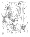
- the machine also comprises an accessory pushing implement 14 located to the front of bottom frame 2 and in turn comprising a transverse front push blade 15 connected to bucket 10 on one side and to bottom frame 2 on the other.
- blade 15 is connected to bucket 10 by an articulated joint 16 ( Figures 1 and 4 ) which, as shown in Figure 4 , comprises an intermediate member 18 and a spherical-headed member 19.
- Intermediate member 18 comprises a shank 20 housed inside a retaining seat in intermediate member 18 and held inside the seat by a pin 21 crosswise to shank 20.
- Member 18 also comprises a spherical head 22 which projects inside bucket 10 through a hole in the bottom wall 23 of bucket 10, and engages a spherical seat 24 on the inside surface of bottom wall 23.
- an end portion 25, opposite spherical head 22, of intermediate member 18 defines a spherical seat engaged by a spherical head 26 fitted through with a pin 27, the opposite ends of which engage a fork 28 so as to rotate about the axis 27a of pin 27 and slide axially between two axial limit positions.
- blade 15 of implement 14 is connected to bottom frame 2 by a connecting assembly 30 comprising a tubular accessory connecting structure 31 which is substantially U-shaped ( Figure 2 ), is made of welded metal plates, and comprises two longitudinal arms 32 and a front crosspiece 33.
- Each arm 32 is located outwards of a respective track 3, and has a rear end portion 32a hinged to bottom frame 2 to rotate about a common hinge axis 34 perpendicular to axes 4 and 7 and adjacent to axis 7; and a middle portion 33a of crosspiece 33 is connected to blade 15 by a spherical joint 35.
- joint 35 comprises a milled spherical head 36 which engages a spherical seat defined by a member 36a connected integrally to a rear surface of blade 15, and is integral with a shank 37 welded to a connecting plate connected integrally to portion 33a.
- spherical head 36 is hinged to member 36a by a hinge pin 38 perpendicular to the bottom edge 15a of blade 15 and to axis 27a.
- the pin extends inside a through hole 39 formed in head 36 and comprising two portions 39 flaring outwards of the head and of minimum diameter at the centre of head 36.
- joint 35 has no hinge pin 38, and so functions as an ordinary spherical joint.
- implement 14 also comprises two fixed-length, lateral braces/stays 40 associated with respective arms 32 and so located on opposite sides of and at the same distance from joint 35; and a further fixed-length, lateral brace/stay 41.
- Each brace/stay 40 is fitted to a respective bottom lateral end portion 42 of blade 15, adjacent to edge 15a, by a respective joint 43 comprising two hinges with perpendicular axes of rotation. More specifically, each joint 43 comprises an elongated intermediate member 44, one end of which is hinged to a fork 45, connected integrally to relative portion 42, to rotate about an axis 45a perpendicular to axis 27a of pin 27, and the opposite end of which is hinged to a fork 46, on the end of relative brace/stay 40, to rotate about an axis 46a perpendicular to and spaced transversely apart from relative axis 45a.
- Each brace/stay 40 is connected to relative arm 32 by a respective flange 47 welded on one side to one end of brace/stay 40, and on the other side to a known spherical joint 48, the spherical head of which has an integral horizontal shank fitted through one of three upward-projecting appendixes 49, each with a hole, welded to and spaced apart along relative arm 32.
- Brace/stay 41 extends over one of braces/stays 40, is connected to a top lateral end portion 50 of blade 15 by a joint 51 identical to joint 43, converges with relative brace/stay 40 and relative flange 47, and terminates with a fork 52 hinged to relative flange 47 to rotate about an axis 52a parallel to axes 34 and 46a.
- blade 15 is moved with respect to accessory structure 31 by a double-acting hydraulic jack 55 connected hydraulically to valve 13a by two hoses 56 and located, like brace/stay 41, over a relative brace/stay 40.
- Jack 55 comprises a cylinder connected to a top lateral end portion 57, opposite portion 50, of blade 15 by a joint 58 identical to joints 43 and 51, converges with relative brace/stay 40 and relative flange 47, and is hinged to flange 47 to rotate about an axis 47a parallel to axes 34 and 46a.
- blade 15 of machine 1 can be tilted laterally by rotating it one way or the other between two limit positions, with joint 35 as the fulcrum, so the bottom edge 15a of blade 15 forms a positive or negative angle, and at any rate other than zero, with supporting plane P, as shown by the dash line in Figure 5 .
- Tilting edge 15a is made possible by the geometry and arrangement of joints 43, 48, 58, 35 and 16, and the tilt angle is adjustable by moving the output rod 55a of hydraulic jack 55 forward or backward, and at the same time moving bucket 10 one way or the other parallel to axis 27a and with respect to blade 15. Movement of bucket 10 with respect to blade 15 is made possible by the pin 27-fork 28 connection.
- blade 15 From the zero position of blade 15 shown in Figure 1 and by the continuous line in Figure 2 , by disconnecting the pins of joints 48 from appendixes 49 and inserting them inside either of the other appendixes 49 on relative arms 32, blade 15 can be rotated one way or the other about an axis perpendicular to the plane of U-shaped structure 31, with joint 35 still as the fulcrum. Blade 15 can thus be set to various discrete or predetermined positions between two limit positions shown by the dash lines in Figure 2 and symmetrical with respect to the zero position of blade 15.
- flange 47 of each spherical joint 48 is connected firmly, together with joint 48, to a respective slide, which is moved both ways along relative arm 32 by a relative hydraulic jack connected hydraulically to circuit 13, so that the above adjustment of blade 15 is continuous, i.e. blade 15 can be set to any operating position between said two limit positions.
- machine 1 therefore functions as an "excavator”, by featuring a classic excavator structure, but at the same time also functions perfectly as a "bulldozer”, by featuring an impressive, sturdy accessory structure designed and connected to bottom frame 2 in such a way as to connect blades of the same type normally used on conventional "bulldozers".
- the assembly connecting blade 15 to the accessory connecting structure is equally sturdy and so unaffected by stress transmitted by blade 15.
- accessory implement 14 calls for no additions or alterations to conventional excavators, either as regards mechanical connections or, above all, hydraulic power transmission, since the one actuator for tilting the blade with respect to the track supporting plane P is fitted to the accessory structure and is simply connected to the existing hydraulic power take-off on articulated boom 9.
- accessory implement 14 can be connected quickly and easily to both bottom frame 2 and bucket 10.
- the particular articulated joint between bucket 10 and blade 15 obviously provides, on the one hand, for simplifying adjustment of blade 15 with respect to accessory structure 31, and, on the other, for highly stable connection of blade 15 to boom 9, even in the presence of severe stress, by being substantially unaffected by the type and direction of the stress transmitted.
- the machine described therefore enables a big reduction in both initial investment and maintenance cost, by not only being convertible, but also, when converted, by performing the exact same functions as a conventional special-purpose machine.
Landscapes
- Engineering & Computer Science (AREA)
- Mechanical Engineering (AREA)
- Mining & Mineral Resources (AREA)
- Civil Engineering (AREA)
- General Engineering & Computer Science (AREA)
- Structural Engineering (AREA)
- Operation Control Of Excavators (AREA)
- Soil Working Implements (AREA)
Claims (15)
- Planierzusatz-Anbaugerät (14) für eine konvertierbare Erdbewegungsmaschine (1) mit einem selbst fahrenden unteren Rahmen (2), einem oberen Rahmen (5), der gegenüber dem unteren Rahmen (2) beweglich ist, einem gelenkig befestigten Ausleger (9), der mit dem oberen Rahmen (5) verbunden und mit einem Arbeitsgerät (10) versehen ist, einem Haupt-Hydraulikkreis zur Versorgung des gelenkig befestigten Auslegers (9) und des Arbeitsgerätes (10) mit Leistung, einem Hilfs-Hydraulikkreis (13) zum Zuführen von Hydraulikflüssigkeit zu Anbaugeräten (14), die mit dem gelenkig befestigten Ausleger (9) verbindbar sind, um mit Verbindungsventil-Einrichtungen (13a), die an dem gelenkig befestigten Ausleger (9) angebracht sind, wobei das Planierzusatz-Anbaugerät Folgendes umfasst: eine Anbaugeräte-Verbindungsstruktur (31), die gelenkig mit dem unteren Rahmen (2) verbindbar ist, um sich um eine erste Gelenkachse (34) zu drehen, und die durch den gelenkig befestigten Ausleger (9) zwischen einer angehobenen Position und einer abgesenkten Position bewegbar ist, eine vordere Planierschaufel (15), die mit der Anbaugeräte-Verbindungsstruktur (31) verbunden ist, und Verbindungseinrichtungen (16) auf der Schaufel (15), die mit dem Arbeitsgerät (14) verbindbar sind; und
dadurch gekennzeichnet, dass das Planierzusatz-Anbaugerät (14) weiterhin Gelenkeinrichtungen (35) umfasst, die zwischen der Anbaugeräte-Verbindungsstruktur (31) und der Schaufel (15) eingefügt sind, wobei hydraulische Betätigungseinrichtungen zwischen der Schaufel (15) und der Anbaugeräte-Verbindungsstruktur (31) eingefügt sind, um die Schaufel (15) gegenüber der Anbaugeräte-Verbindungsstruktur (31) um zumindest eine weitere Gelenkachse zu bewegen" die im Wesentlichen unter einem rechten Winkel zu der ersten Gelenkachse (34) steht, und wobei die hydraulischen Betätigungseinrichtungen (55) Leitungen umfassen, die hydraulisch mit den Verbindungsventil-Einrichtungen (13a) des gelenkig befestigten Auslegers verbindbar sind. - Anbaugerät (14) nach Anspruch 1, dadurch gekennzeichnet, dass die Gelenkeinrichtungen (35) in der Mitte liegende Kugelgelenk-Einrichtungen, eine Anordnung von seitlichen Streben/Stangen (40, 41); erste Verbindungsgelenke (43) zum Verbinden jeder der Streben/Stangen (40, 41) mit der Schaufel (15); und zweite Verbindungsgelenke (48) zum Verbinden der Streben/Stangen (40, 41) mit der Anbaugeräte-Vebindungsstruktur (31) umfassen.
- Anbaugerät (14) nach Anspruch 1 oder 2, dadurch gekennzeichnet, dass die Anbaugeräte-Verbindungsstruktur (31) im Wesentlichen U-förmig ist und zwei längs gerichtete Arme (32) umfasst, die auf entgegengesetzten Seiten des unteren Rahmens (2) liegen.
- Anbaugerät (14) nach einem der Ansprüche 1 bis 3, dadurch gekennzeichnet, dass jedes erste Verbindungsgelenk (43) erste und zweite Gelenkeinrichtungen (45, 46) umfasst, die jeweils eine erste und eine zweite Drehachse (45a, 46a) unter einem rechten Winkel zueinander und in einem Abstand in der Querrichtung der Schaufel aufweisen.
- Anbaugerät (14) nach den Ansprüchen 2 bis 4, dadurch gekennzeichnet, dass jedes zweite Verbindungsgelenk (48) ein Kugelgelenk umfasst.
- Anbaugerät (14) nach einem der Ansprüche 2 bis 5, dadurch gekennzeichnet, dass jedes der Verbindungsgelenke (48) in Längsrichtung entlang der Anbaugeräte-Struktur (31) beweglich ist, um die Neigung der Schaufel (15) um eine dritte Gelenkachse einzustellen, die im Wesentlichen unter einem rechten Winkel zu der ersten Gelenkachse steht.
- Anbaugerät (14) nach Anspruch 6, dadurch gekennzeichnet, dass die zweiten Verbindungsgelenke (48) selektiv mit diskreten Punkten der Anbaugeräte-Struktur (31) verbindbar sind.
- Anbaugerät (14) nach Anspruch 6, dadurch gekennzeichnet, dass es weitere hydraulische Betätigungseinrichtungen umfasst, die zwischen jedem der zweiten Verbindungsgelenke (48) und der Anbaugeräte-Verbindungsstruktur (31) eingefügt sind, um kontinuierlich die Position der Schaufel (15) um die dritte Gelenkachse einzustellen.
- Anbaugerät (14) nach Anspruch 8, dadurch gekennzeichnet, dass die weiteren hydraulischen Betätigungseinrichtungen hydraulisch mit dem Hilfs-Hydraulikkreis verbunden sind.
- Anbaugerät (14) nach einem der vorhergehenden Ansprüche, dadurch gekennzeichnet, dass die hydraulischen Betätigungseinrichtungen (55) ein einfach wirkendes hydraulisches Stellglied umfassen, das zwischen der Anbaugeräte-Struktur (31) und der Schaufel (15) eingefügt ist.
- Anbaugerät (14) nach Anspruch 10, dadurch gekennzeichnet, dass das einfach wirkende hydraulische Stellglied mit der Anbaugeräte-Struktur (31) durch ein Gelenk (58) verbunden ist, das erste und zweite Gelenkeinrichtungen umfasst, die jeweils eine vierte und eine fünfte Gelenkachse unter einem rechten Winkel zueinander aufweisen und in Querrichtung in Abstand voneinander angeordnet sind.
- Anbaugerät (14) nach einem der vorhergehenden Ansprüche, dadurch gekennzeichnet, dass die Verbindungseinrichtungen (16) Kugelgelenk-Einrichtungen umfassen.
- Anbaugerät (14) nach Anspruch 12, dadurch gekennzeichnet, dass die Kugelgelenk-Einrichtungen ein Paar von Kugelgelenken in Serie umfassen.
- Anbaugerät (14) nach Anspruch 13, dadurch gekennzeichnet, dass das Paar von Kugelgelenken ein gemeinsames Zwischenelement umfasst, das einen kugelförmigen Kopf von einem der Kugelgelenke und einen kugelförmigen Sitz des anderen der kugelförmigen Gelenke umfasst, und dass der kugelförmige Kopf lösbar mit dem Zwischenelement verbunden ist, wobei der kugelförmige Kopf mit einem kugelförmigen Sitz in dem Arbeitsgerät in Eingriff steht.
- Konvertierbare Erdbewegungsmaschine (1), mit einem selbst fahrenden unteren Rahmen (2), einem oberen Rahmen (5), der gegenüber dem unteren Rahmen (2) beweglich ist, einen gelenkig befestigten Ausleger (9), der mit dem oberen Rahmen (5) verbunden und mit einem Arbeitsgerät (10) versehen ist, einem Haupt-Hydraulikkreis zur Versorgung des gelenkig befestigten Auslegers (9) und des Arbeitsgerätes (10) mit Leistung, einem Hilfs-Hydraulikkreis (13) zum Zuführen von Hydraulikflüssigkeit an Anbaugeräte (14), die mit dem gelenkig befestigten Ausleger (9) verbindbar sind, und Verbindungsventil-Einrichtungen, die an dem gelenkig befestigten Ausleger (9) angebracht sind, und einem Planierzusatz-Anbaugerät (14) nach einem der vorhergehenden Ansprüche.
Applications Claiming Priority (1)
| Application Number | Priority Date | Filing Date | Title |
|---|---|---|---|
| ITTO2008A000861A IT1391878B1 (it) | 2008-11-21 | 2008-11-21 | Macchina movimento terra convertibile ed attrezzatura addizionale per detta macchina |
Publications (2)
| Publication Number | Publication Date |
|---|---|
| EP2189578A1 EP2189578A1 (de) | 2010-05-26 |
| EP2189578B1 true EP2189578B1 (de) | 2013-07-24 |
Family
ID=40888201
Family Applications (1)
| Application Number | Title | Priority Date | Filing Date |
|---|---|---|---|
| EP20090176786 Active EP2189578B1 (de) | 2008-11-21 | 2009-11-23 | Zusatzplaniergerüst für konvertierbare Baumaschine |
Country Status (2)
| Country | Link |
|---|---|
| EP (1) | EP2189578B1 (de) |
| IT (1) | IT1391878B1 (de) |
Cited By (2)
| Publication number | Priority date | Publication date | Assignee | Title |
|---|---|---|---|---|
| US12577753B1 (en) * | 2022-11-23 | 2026-03-17 | Jacob Aaron Bitner | Bulldozer implement quick connect and release system |
| US12606979B2 (en) * | 2023-07-06 | 2026-04-21 | Glenn Fuerstenberg | Dump liner device |
Families Citing this family (1)
| Publication number | Priority date | Publication date | Assignee | Title |
|---|---|---|---|---|
| GB2587226B (en) * | 2019-09-19 | 2023-10-04 | Bamford Excavators Ltd | A working machine |
Family Cites Families (9)
| Publication number | Priority date | Publication date | Assignee | Title |
|---|---|---|---|---|
| US3386519A (en) * | 1965-06-30 | 1968-06-04 | Case Co J I | Hydraulic cylinder mounting |
| US3628612A (en) * | 1969-09-08 | 1971-12-21 | Caterpillar Tractor Co | Mounting arrangement for bulldozer blades |
| US3648782A (en) * | 1969-11-19 | 1972-03-14 | Gen Motors Corp | Multipurpose bulldozer assembly |
| JPS4863902U (de) * | 1971-11-19 | 1973-08-14 | ||
| JP2521007Y2 (ja) * | 1990-05-31 | 1996-12-25 | 油谷重工株式会社 | 小型ショベルのドーザ装置 |
| SE9203368L (sv) * | 1992-11-11 | 1993-11-22 | Lennart Nilsson | Anordning vid maskin såsom hjullastare och dylikt för att utjämna inverkan av ojämnheter i underlaget |
| GB2341167B (en) * | 1999-01-25 | 2000-07-19 | David Douglas Cook | Quick hitch dozer blade to mount on tracked or wheeled 360 degree hydraulic excavator |
| JP3443373B2 (ja) * | 1999-09-13 | 2003-09-02 | コベルコ建機株式会社 | 油圧管の配管構造 |
| US6493967B2 (en) * | 2000-05-26 | 2002-12-17 | Frederick J. Holmes | Apparatus for attaching an accessory to an excavator |
-
2008
- 2008-11-21 IT ITTO2008A000861A patent/IT1391878B1/it active
-
2009
- 2009-11-23 EP EP20090176786 patent/EP2189578B1/de active Active
Cited By (2)
| Publication number | Priority date | Publication date | Assignee | Title |
|---|---|---|---|---|
| US12577753B1 (en) * | 2022-11-23 | 2026-03-17 | Jacob Aaron Bitner | Bulldozer implement quick connect and release system |
| US12606979B2 (en) * | 2023-07-06 | 2026-04-21 | Glenn Fuerstenberg | Dump liner device |
Also Published As
| Publication number | Publication date |
|---|---|
| IT1391878B1 (it) | 2012-01-27 |
| EP2189578A1 (de) | 2010-05-26 |
| ITTO20080861A1 (it) | 2010-05-22 |
Similar Documents
| Publication | Publication Date | Title |
|---|---|---|
| US5403144A (en) | Blade tilt assembly for a front end loader | |
| US7264435B2 (en) | Lift boom assembly | |
| CA1106596A (en) | Adjustment mechanism for dozer blade | |
| US20140271078A1 (en) | Lift arm structure with an articulated knee portion | |
| EP1997964B1 (de) | Arbeitsmaschine mit einer drehbaren Fahrerkabine | |
| US6539650B2 (en) | Swivel mounting for quick attachment bracket | |
| US20090044434A1 (en) | Hydraulic Control System for a Swiveling Construction Machine | |
| US11142885B2 (en) | Mechanical self-leveling lift arm structure for power machine | |
| US20070128012A1 (en) | Industrial vehicle having working implement | |
| US20190127194A1 (en) | Excavator man-lift | |
| EP4341494B1 (de) | Selbstnivellierende hubarmvorrichtung für arbeitsmaschinen | |
| CN106170595A (zh) | 用于建筑机械的提升布置 | |
| CN108713081A (zh) | 轮式装载机前部单元以及轮式装载机 | |
| EP2189578B1 (de) | Zusatzplaniergerüst für konvertierbare Baumaschine | |
| CN107023045A (zh) | 用于工程机械的自调平机构 | |
| JP2017006080A (ja) | 草刈機 | |
| JP6598292B2 (ja) | 草刈機 | |
| US10760243B2 (en) | Work tool attachment for a work machine | |
| WO2012122439A2 (en) | Tilt cylinder support structure | |
| JP2021008741A (ja) | 作業機の油圧システム及び作業機 | |
| EP2362023A1 (de) | Hydraulikantriebssystem für Baumaschinen | |
| CN110552390A (zh) | 一种施工机械的工具更换器 | |
| JP2019156313A (ja) | クランプアームを備えた解体機械 | |
| JP2012017589A (ja) | フロントローダの制御装置 | |
| EP1154081A2 (de) | Machine mit einem Arbeitsarm |
Legal Events
| Date | Code | Title | Description |
|---|---|---|---|
| PUAI | Public reference made under article 153(3) epc to a published international application that has entered the european phase |
Free format text: ORIGINAL CODE: 0009012 |
|
| AK | Designated contracting states |
Kind code of ref document: A1 Designated state(s): AT BE BG CH CY CZ DE DK EE ES FI FR GB GR HR HU IE IS IT LI LT LU LV MC MK MT NL NO PL PT RO SE SI SK SM TR |
|
| 17P | Request for examination filed |
Effective date: 20101126 |
|
| 17Q | First examination report despatched |
Effective date: 20110112 |
|
| RAP1 | Party data changed (applicant data changed or rights of an application transferred) |
Owner name: NEW HOLLAND KOBELCO CONSTRUCTION MACHINERY S.P.A. |
|
| RIC1 | Information provided on ipc code assigned before grant |
Ipc: E02F 3/96 20060101ALI20121218BHEP Ipc: E02F 3/815 20060101AFI20121218BHEP |
|
| GRAP | Despatch of communication of intention to grant a patent |
Free format text: ORIGINAL CODE: EPIDOSNIGR1 |
|
| GRAS | Grant fee paid |
Free format text: ORIGINAL CODE: EPIDOSNIGR3 |
|
| GRAA | (expected) grant |
Free format text: ORIGINAL CODE: 0009210 |
|
| AK | Designated contracting states |
Kind code of ref document: B1 Designated state(s): AT BE BG CH CY CZ DE DK EE ES FI FR GB GR HR HU IE IS IT LI LT LU LV MC MK MT NL NO PL PT RO SE SI SK SM TR |
|
| REG | Reference to a national code |
Ref country code: GB Ref legal event code: FG4D |
|
| REG | Reference to a national code |
Ref country code: CH Ref legal event code: EP |
|
| REG | Reference to a national code |
Ref country code: AT Ref legal event code: REF Ref document number: 623568 Country of ref document: AT Kind code of ref document: T Effective date: 20130815 |
|
| REG | Reference to a national code |
Ref country code: IE Ref legal event code: FG4D |
|
| REG | Reference to a national code |
Ref country code: DE Ref legal event code: R096 Ref document number: 602009017372 Country of ref document: DE Effective date: 20130919 |
|
| REG | Reference to a national code |
Ref country code: AT Ref legal event code: MK05 Ref document number: 623568 Country of ref document: AT Kind code of ref document: T Effective date: 20130724 |
|
| REG | Reference to a national code |
Ref country code: NL Ref legal event code: VDEP Effective date: 20130724 |
|
| REG | Reference to a national code |
Ref country code: LT Ref legal event code: MG4D |
|
| PG25 | Lapsed in a contracting state [announced via postgrant information from national office to epo] |
Ref country code: PT Free format text: LAPSE BECAUSE OF FAILURE TO SUBMIT A TRANSLATION OF THE DESCRIPTION OR TO PAY THE FEE WITHIN THE PRESCRIBED TIME-LIMIT Effective date: 20131125 Ref country code: LT Free format text: LAPSE BECAUSE OF FAILURE TO SUBMIT A TRANSLATION OF THE DESCRIPTION OR TO PAY THE FEE WITHIN THE PRESCRIBED TIME-LIMIT Effective date: 20130724 Ref country code: NO Free format text: LAPSE BECAUSE OF FAILURE TO SUBMIT A TRANSLATION OF THE DESCRIPTION OR TO PAY THE FEE WITHIN THE PRESCRIBED TIME-LIMIT Effective date: 20131024 Ref country code: BE Free format text: LAPSE BECAUSE OF FAILURE TO SUBMIT A TRANSLATION OF THE DESCRIPTION OR TO PAY THE FEE WITHIN THE PRESCRIBED TIME-LIMIT Effective date: 20130724 Ref country code: SE Free format text: LAPSE BECAUSE OF FAILURE TO SUBMIT A TRANSLATION OF THE DESCRIPTION OR TO PAY THE FEE WITHIN THE PRESCRIBED TIME-LIMIT Effective date: 20130724 Ref country code: CY Free format text: LAPSE BECAUSE OF FAILURE TO SUBMIT A TRANSLATION OF THE DESCRIPTION OR TO PAY THE FEE WITHIN THE PRESCRIBED TIME-LIMIT Effective date: 20130828 Ref country code: HR Free format text: LAPSE BECAUSE OF FAILURE TO SUBMIT A TRANSLATION OF THE DESCRIPTION OR TO PAY THE FEE WITHIN THE PRESCRIBED TIME-LIMIT Effective date: 20130724 Ref country code: AT Free format text: LAPSE BECAUSE OF FAILURE TO SUBMIT A TRANSLATION OF THE DESCRIPTION OR TO PAY THE FEE WITHIN THE PRESCRIBED TIME-LIMIT Effective date: 20130724 Ref country code: IS Free format text: LAPSE BECAUSE OF FAILURE TO SUBMIT A TRANSLATION OF THE DESCRIPTION OR TO PAY THE FEE WITHIN THE PRESCRIBED TIME-LIMIT Effective date: 20131124 |
|
| PG25 | Lapsed in a contracting state [announced via postgrant information from national office to epo] |
Ref country code: PL Free format text: LAPSE BECAUSE OF FAILURE TO SUBMIT A TRANSLATION OF THE DESCRIPTION OR TO PAY THE FEE WITHIN THE PRESCRIBED TIME-LIMIT Effective date: 20130724 Ref country code: GR Free format text: LAPSE BECAUSE OF FAILURE TO SUBMIT A TRANSLATION OF THE DESCRIPTION OR TO PAY THE FEE WITHIN THE PRESCRIBED TIME-LIMIT Effective date: 20131025 Ref country code: SI Free format text: LAPSE BECAUSE OF FAILURE TO SUBMIT A TRANSLATION OF THE DESCRIPTION OR TO PAY THE FEE WITHIN THE PRESCRIBED TIME-LIMIT Effective date: 20130724 Ref country code: NL Free format text: LAPSE BECAUSE OF FAILURE TO SUBMIT A TRANSLATION OF THE DESCRIPTION OR TO PAY THE FEE WITHIN THE PRESCRIBED TIME-LIMIT Effective date: 20130724 Ref country code: LV Free format text: LAPSE BECAUSE OF FAILURE TO SUBMIT A TRANSLATION OF THE DESCRIPTION OR TO PAY THE FEE WITHIN THE PRESCRIBED TIME-LIMIT Effective date: 20130724 Ref country code: FI Free format text: LAPSE BECAUSE OF FAILURE TO SUBMIT A TRANSLATION OF THE DESCRIPTION OR TO PAY THE FEE WITHIN THE PRESCRIBED TIME-LIMIT Effective date: 20130724 |
|
| PG25 | Lapsed in a contracting state [announced via postgrant information from national office to epo] |
Ref country code: CY Free format text: LAPSE BECAUSE OF FAILURE TO SUBMIT A TRANSLATION OF THE DESCRIPTION OR TO PAY THE FEE WITHIN THE PRESCRIBED TIME-LIMIT Effective date: 20130724 |
|
| PG25 | Lapsed in a contracting state [announced via postgrant information from national office to epo] |
Ref country code: RO Free format text: LAPSE BECAUSE OF FAILURE TO SUBMIT A TRANSLATION OF THE DESCRIPTION OR TO PAY THE FEE WITHIN THE PRESCRIBED TIME-LIMIT Effective date: 20130724 Ref country code: SK Free format text: LAPSE BECAUSE OF FAILURE TO SUBMIT A TRANSLATION OF THE DESCRIPTION OR TO PAY THE FEE WITHIN THE PRESCRIBED TIME-LIMIT Effective date: 20130724 Ref country code: DK Free format text: LAPSE BECAUSE OF FAILURE TO SUBMIT A TRANSLATION OF THE DESCRIPTION OR TO PAY THE FEE WITHIN THE PRESCRIBED TIME-LIMIT Effective date: 20130724 Ref country code: CZ Free format text: LAPSE BECAUSE OF FAILURE TO SUBMIT A TRANSLATION OF THE DESCRIPTION OR TO PAY THE FEE WITHIN THE PRESCRIBED TIME-LIMIT Effective date: 20130724 Ref country code: EE Free format text: LAPSE BECAUSE OF FAILURE TO SUBMIT A TRANSLATION OF THE DESCRIPTION OR TO PAY THE FEE WITHIN THE PRESCRIBED TIME-LIMIT Effective date: 20130724 |
|
| PG25 | Lapsed in a contracting state [announced via postgrant information from national office to epo] |
Ref country code: ES Free format text: LAPSE BECAUSE OF FAILURE TO SUBMIT A TRANSLATION OF THE DESCRIPTION OR TO PAY THE FEE WITHIN THE PRESCRIBED TIME-LIMIT Effective date: 20130724 |
|
| PLBE | No opposition filed within time limit |
Free format text: ORIGINAL CODE: 0009261 |
|
| STAA | Information on the status of an ep patent application or granted ep patent |
Free format text: STATUS: NO OPPOSITION FILED WITHIN TIME LIMIT |
|
| REG | Reference to a national code |
Ref country code: CH Ref legal event code: PL |
|
| 26N | No opposition filed |
Effective date: 20140425 |
|
| PG25 | Lapsed in a contracting state [announced via postgrant information from national office to epo] |
Ref country code: MC Free format text: LAPSE BECAUSE OF FAILURE TO SUBMIT A TRANSLATION OF THE DESCRIPTION OR TO PAY THE FEE WITHIN THE PRESCRIBED TIME-LIMIT Effective date: 20130724 Ref country code: CH Free format text: LAPSE BECAUSE OF NON-PAYMENT OF DUE FEES Effective date: 20131130 Ref country code: LI Free format text: LAPSE BECAUSE OF NON-PAYMENT OF DUE FEES Effective date: 20131130 |
|
| REG | Reference to a national code |
Ref country code: DE Ref legal event code: R097 Ref document number: 602009017372 Country of ref document: DE Effective date: 20140425 |
|
| REG | Reference to a national code |
Ref country code: IE Ref legal event code: MM4A |
|
| PG25 | Lapsed in a contracting state [announced via postgrant information from national office to epo] |
Ref country code: IE Free format text: LAPSE BECAUSE OF NON-PAYMENT OF DUE FEES Effective date: 20131123 |
|
| PG25 | Lapsed in a contracting state [announced via postgrant information from national office to epo] |
Ref country code: SM Free format text: LAPSE BECAUSE OF FAILURE TO SUBMIT A TRANSLATION OF THE DESCRIPTION OR TO PAY THE FEE WITHIN THE PRESCRIBED TIME-LIMIT Effective date: 20130724 |
|
| PG25 | Lapsed in a contracting state [announced via postgrant information from national office to epo] |
Ref country code: TR Free format text: LAPSE BECAUSE OF FAILURE TO SUBMIT A TRANSLATION OF THE DESCRIPTION OR TO PAY THE FEE WITHIN THE PRESCRIBED TIME-LIMIT Effective date: 20130724 |
|
| PG25 | Lapsed in a contracting state [announced via postgrant information from national office to epo] |
Ref country code: LU Free format text: LAPSE BECAUSE OF NON-PAYMENT OF DUE FEES Effective date: 20131123 Ref country code: MK Free format text: LAPSE BECAUSE OF FAILURE TO SUBMIT A TRANSLATION OF THE DESCRIPTION OR TO PAY THE FEE WITHIN THE PRESCRIBED TIME-LIMIT Effective date: 20130724 Ref country code: BG Free format text: LAPSE BECAUSE OF FAILURE TO SUBMIT A TRANSLATION OF THE DESCRIPTION OR TO PAY THE FEE WITHIN THE PRESCRIBED TIME-LIMIT Effective date: 20130724 Ref country code: HU Free format text: LAPSE BECAUSE OF FAILURE TO SUBMIT A TRANSLATION OF THE DESCRIPTION OR TO PAY THE FEE WITHIN THE PRESCRIBED TIME-LIMIT; INVALID AB INITIO Effective date: 20091123 |
|
| PG25 | Lapsed in a contracting state [announced via postgrant information from national office to epo] |
Ref country code: MT Free format text: LAPSE BECAUSE OF FAILURE TO SUBMIT A TRANSLATION OF THE DESCRIPTION OR TO PAY THE FEE WITHIN THE PRESCRIBED TIME-LIMIT Effective date: 20130724 |
|
| REG | Reference to a national code |
Ref country code: FR Ref legal event code: PLFP Year of fee payment: 7 |
|
| REG | Reference to a national code |
Ref country code: FR Ref legal event code: PLFP Year of fee payment: 8 |
|
| REG | Reference to a national code |
Ref country code: FR Ref legal event code: PLFP Year of fee payment: 9 |
|
| REG | Reference to a national code |
Ref country code: FR Ref legal event code: PLFP Year of fee payment: 10 |
|
| PGFP | Annual fee paid to national office [announced via postgrant information from national office to epo] |
Ref country code: DE Payment date: 20191128 Year of fee payment: 11 |
|
| PGFP | Annual fee paid to national office [announced via postgrant information from national office to epo] |
Ref country code: FR Payment date: 20191124 Year of fee payment: 11 |
|
| PGFP | Annual fee paid to national office [announced via postgrant information from national office to epo] |
Ref country code: GB Payment date: 20191122 Year of fee payment: 11 |
|
| REG | Reference to a national code |
Ref country code: DE Ref legal event code: R119 Ref document number: 602009017372 Country of ref document: DE |
|
| REG | Reference to a national code |
Ref country code: DE Ref legal event code: R082 Ref document number: 602009017372 Country of ref document: DE Representative=s name: MEISSNER BOLTE PATENTANWAELTE RECHTSANWAELTE P, DE |
|
| GBPC | Gb: european patent ceased through non-payment of renewal fee |
Effective date: 20201123 |
|
| PG25 | Lapsed in a contracting state [announced via postgrant information from national office to epo] |
Ref country code: FR Free format text: LAPSE BECAUSE OF NON-PAYMENT OF DUE FEES Effective date: 20201130 |
|
| PG25 | Lapsed in a contracting state [announced via postgrant information from national office to epo] |
Ref country code: GB Free format text: LAPSE BECAUSE OF NON-PAYMENT OF DUE FEES Effective date: 20201123 Ref country code: DE Free format text: LAPSE BECAUSE OF NON-PAYMENT OF DUE FEES Effective date: 20210601 |
|
| PGFP | Annual fee paid to national office [announced via postgrant information from national office to epo] |
Ref country code: IT Payment date: 20241125 Year of fee payment: 16 |