EP2189589B1 - Agencement de panneau en bois et panneau en bois pour cet agencement - Google Patents
Agencement de panneau en bois et panneau en bois pour cet agencement Download PDFInfo
- Publication number
- EP2189589B1 EP2189589B1 EP09014606A EP09014606A EP2189589B1 EP 2189589 B1 EP2189589 B1 EP 2189589B1 EP 09014606 A EP09014606 A EP 09014606A EP 09014606 A EP09014606 A EP 09014606A EP 2189589 B1 EP2189589 B1 EP 2189589B1
- Authority
- EP
- European Patent Office
- Prior art keywords
- groove
- tongue
- panel
- wood
- panels
- Prior art date
- Legal status (The legal status is an assumption and is not a legal conclusion. Google has not performed a legal analysis and makes no representation as to the accuracy of the status listed.)
- Not-in-force
Links
- 239000002023 wood Substances 0.000 title claims abstract description 59
- 239000000463 material Substances 0.000 claims description 9
- 230000008961 swelling Effects 0.000 claims description 5
- 238000010276 construction Methods 0.000 claims description 3
- 230000008878 coupling Effects 0.000 claims 28
- 238000010168 coupling process Methods 0.000 claims 28
- 238000005859 coupling reaction Methods 0.000 claims 28
- 210000001331 nose Anatomy 0.000 claims 7
- 230000001419 dependent effect Effects 0.000 claims 1
- 210000000887 face Anatomy 0.000 claims 1
- 239000006228 supernatant Substances 0.000 description 9
- 238000006073 displacement reaction Methods 0.000 description 4
- 238000003780 insertion Methods 0.000 description 4
- 230000037431 insertion Effects 0.000 description 4
- 238000004519 manufacturing process Methods 0.000 description 3
- 230000008901 benefit Effects 0.000 description 2
- 230000015572 biosynthetic process Effects 0.000 description 2
- 230000008859 change Effects 0.000 description 2
- 238000001035 drying Methods 0.000 description 2
- 230000000694 effects Effects 0.000 description 2
- 230000003993 interaction Effects 0.000 description 2
- 230000013011 mating Effects 0.000 description 2
- 239000002699 waste material Substances 0.000 description 2
- 230000000712 assembly Effects 0.000 description 1
- 238000000429 assembly Methods 0.000 description 1
- 239000002131 composite material Substances 0.000 description 1
- 150000001875 compounds Chemical class 0.000 description 1
- 238000005562 fading Methods 0.000 description 1
- 230000002349 favourable effect Effects 0.000 description 1
- 210000003746 feather Anatomy 0.000 description 1
- 238000009472 formulation Methods 0.000 description 1
- 238000009434 installation Methods 0.000 description 1
- 238000009413 insulation Methods 0.000 description 1
- 238000000034 method Methods 0.000 description 1
- 239000000203 mixture Substances 0.000 description 1
- 230000008569 process Effects 0.000 description 1
- 239000007787 solid Substances 0.000 description 1
- 230000007704 transition Effects 0.000 description 1
- 230000000007 visual effect Effects 0.000 description 1
Images

Classifications
-
- E—FIXED CONSTRUCTIONS
- E04—BUILDING
- E04F—FINISHING WORK ON BUILDINGS, e.g. STAIRS, FLOORS
- E04F15/00—Flooring
- E04F15/02—Flooring or floor layers composed of a number of similar elements
- E04F15/04—Flooring or floor layers composed of a number of similar elements only of wood or with a top layer of wood, e.g. with wooden or metal connecting members
-
- E—FIXED CONSTRUCTIONS
- E04—BUILDING
- E04F—FINISHING WORK ON BUILDINGS, e.g. STAIRS, FLOORS
- E04F13/00—Coverings or linings, e.g. for walls or ceilings
- E04F13/07—Coverings or linings, e.g. for walls or ceilings composed of covering or lining elements; Sub-structures therefor; Fastening means therefor
- E04F13/08—Coverings or linings, e.g. for walls or ceilings composed of covering or lining elements; Sub-structures therefor; Fastening means therefor composed of a plurality of similar covering or lining elements
- E04F13/10—Coverings or linings, e.g. for walls or ceilings composed of covering or lining elements; Sub-structures therefor; Fastening means therefor composed of a plurality of similar covering or lining elements of wood or with an outer layer of wood
-
- E—FIXED CONSTRUCTIONS
- E04—BUILDING
- E04F—FINISHING WORK ON BUILDINGS, e.g. STAIRS, FLOORS
- E04F2201/00—Joining sheets or plates or panels
- E04F2201/01—Joining sheets, plates or panels with edges in abutting relationship
- E04F2201/0107—Joining sheets, plates or panels with edges in abutting relationship by moving the sheets, plates or panels substantially in their own plane, perpendicular to the abutting edges
- E04F2201/0115—Joining sheets, plates or panels with edges in abutting relationship by moving the sheets, plates or panels substantially in their own plane, perpendicular to the abutting edges with snap action of the edge connectors
-
- E—FIXED CONSTRUCTIONS
- E04—BUILDING
- E04F—FINISHING WORK ON BUILDINGS, e.g. STAIRS, FLOORS
- E04F2201/00—Joining sheets or plates or panels
- E04F2201/01—Joining sheets, plates or panels with edges in abutting relationship
- E04F2201/0153—Joining sheets, plates or panels with edges in abutting relationship by rotating the sheets, plates or panels around an axis which is parallel to the abutting edges, possibly combined with a sliding movement
Definitions
- the invention relates to a wooden panel arrangement consisting of at least two juxtaposed, interconnected wooden panels, in particular wall, ceiling or floor panels, wherein the panel has a particular designed as a visible surface top and a top side opposite bottom and the top and bottom connecting end faces , wherein a first wooden panel is provided on at least one of its end faces with a groove and a second wooden panel on at least one of its end faces with a spring.
- the invention also relates to a wood panel for a wood panel arrangement, wherein the wood panel arrangement consists of a plurality of individual wood panels, wherein the single wood panel has top and bottom sides joined by end faces, and a first end face has a groove and a second end face a spring ,
- Panel assemblies with panels having tongue and groove are prior art.
- these Paneelanordnuhgen there is the disadvantage that in case of shrinkage of the material of the panels, especially in wood panels, the spring slips out of the groove and between the panels creates a continuous gap. Such gaps are undesirable in a laid panel arrangement.
- the visual impression is insufficient and, on the other hand, if necessary cold bridges are created by this gap which should also be avoided.
- the GB 2 256 023 A shows a connection for a wooden panel arrangement, in which a locking element arranged on a spring engages in a groove provided in the detent element and thus to prevent divergence of the panels when swelling or shrinkage.
- a permanent permanent connection between the wood panels which would prevent complete divergence, can not be prevented by the apparatus disclosed herein.
- room conditions e.g., humidity or temperature
- relative positions are meant the positions of the panels in which the panels move in a region between two end positions such that in a first end position the spring is up to a maximum into the groove and in a second end position both panels are so far apart are arranged, that the latching means cooperating with the latching element latching and the spring just barely into the groove.
- a longitudinal expansion or shrinkage of the individual panels can be compensated for without the entire panel arrangement being changed in its external dimensions or being changed only insignificantly. Only with further fading of the individual panels causes the latching, that a first panel moves with another.
- the latching means according to the invention has such a configuration that causes a fixation of the spring of a panel in the groove of the other panel, so that a stable connection is formed and in a further loss, for example, then possibly a next panel, in which still some margin in the groove is present, pulls with it. Due to the large number of tongue and groove joints in a panel arrangement, a total compensation is achieved, so that slipping out of the spring from the grooves, as it is unfortunately to be recorded in the prior art as undesirable concomitant, no longer occurs.
- the invention accordingly achieves the stated object by virtue of the fact that the latching means and the latching element cooperate in an "end position" in such a latching manner that the spring at least partially still projects into the groove and thus the gap between the two panels can not arise.
- the latching element is arranged in the head region of the spring, an optimal utilization of the groove depth, which is arranged in the end face of the wood panel groove is achieved.
- the head area is the area on the spring which faces away from the remaining viewing area of the panel, that is to say is remote, and the panel is bordered on the edge in the area of the spring.
- the upper end region of the head region of the spring abuts, for example (in the gap-free arrangement) on the groove bottom of the groove.
- the Erfingung therefore cleverly combined a (at any time) gap-free and therefore visually appealing panel assembly with good insulation effect of the panel, as due to the gap-free design a corresponding exchange of air to (cold) substructure is avoided or hindered, with the most cost-effective production, as waste and avoidable supernatants due to the clever arrangement of Verrastungsettis in the head area is avoided.
- the invention ensures that the shrinkage of the wood, which depends on the change in the moisture content of the wood (up to 0.22% per one percent change in the wood moisture content), does not lead to the formation of a gap. The noticeable shrinkage behavior does not lead to a visible gap in the arrangement according to the invention!
- the term "panels” also refers expressly to wood panels, although not expressly stated.
- the panel assembly is arranged on a substructure, which consists for example of a screed, a slatted or wooden construction, a wall or a ceiling.
- the individual panels can be firmly connected to the substructure.
- the panels can be nailed to the substructure or fastened with clips.
- the individual panels are fixed in their position. In the case of shrinkage of the material of the panels, the individual panels contract and the spring of one panel retreats from the groove of the adjacent panel. However, this is only possible up to the end position of the relative position in the latching means and Verrastungselement cooperate with each other. Another loss is not possible.
- the head area comprises at least half the depth of the spring.
- the head region of the spring is the first region of the spring, which dips into the groove of the adjacent wooden panel during the mating of the individual wooden panels.
- the invention provides that the latching element of the spring is arranged in the front head area.
- the head area about half preferably about 50%, but possibly also up to 60%, which also applies as a center according to the invention
- the head area is limited to 40%, 25% or even only 10% to 15% of the depth of the spring, if, for example, a correspondingly smaller latching element is arranged on the spring.
- the direction of the depth is defined perpendicular to the longitudinal axis of the profile-like panel and lies in the plane of the panel.
- the invention includes not only solutions in which the latching element begins right in the front end of the head portion of the spring, but is set against this a certain amount.
- a latching element slightly recessed in the head area is shown, whereas in FIG. 4 the locking element at the front end of the spring (also in the head area) begins.
- the panels are to some extent slidably connected to the substructure. They are particularly attached with play in the direction transverse to the longitudinal extent of the panel on the substructure.
- the brackets for example, loosely engage around the lower groove cheek so that the panel is displaceable relative to the clamp.
- the recesses through which nails or screws, with which the clamps are fastened to the substructure protrude, designed as a slot. This version also allows a movable attachment of the panels on the substructure. If there is further shrinkage, when latching means and latching elements are already cooperating, both panels will be attracted towards each other or a first panel towards a second panel or the second towards the first. The movement is limited.
- the panel assembly is floating, that is, the individual panels are not connected to the substructure.
- the panels are placed so close to each other when laying, that the spring of a panel is up to a maximum in the groove of another panel. This is the first end position of the relative positions of the panels to each other. Dries now the single panel and the material shrinks, so the single panel contracts, with the spring of a first panel retreats from the groove of a second panel, but here prevent arranged on tongue and groove latching and Verrastungsetti that the spring can completely slip out of the groove.
- the fade may be compensated for by multiple panels which are laterally offset together by the latching members and means, the fade is compensated to leave the entire panel assembly gapless.
- the panels can be laid even in a dry state.
- the panels in the end position of the panels are mutually, cooperate in the latching means and Verrastungselement. If the wood now swells through moisture, the spring pushes further into the groove without the adjacent panels changing their position.
- panels are laid to each other so that both swelling and shrinkage is possible, that is, both panels are arranged to each other when laying in a central relative position to each other, the spring end is sufficiently spaced from the groove bottom.
- the individual panels are mutually displaceable parallel or perpendicular to the longitudinal direction of the groove and / or spring end faces. You can take different relative positions to each other. A displacement in the direction parallel to the longitudinal extension of the tongue and groove is possible. It could be possible to connect tongue and groove by inserting a panel into another panel. A displacement perpendicular to the longitudinal extent of the tongue and groove is limited by latching means and latching element.
- the recess in which the first groove cheek delimiting groove cheek side is arranged, and the groove bottom facing away from depression recess surface, flush with the Nutwangenstirnseite the second groove cheek, or opposite to this.
- the end face is not necessarily continuous or integrally formed, it can also be discontinued, so be oriented from several sections, with paragraphs or obliquely (not at right angles to the top or bottom).
- the end face is also an end face of the groove cheek, the respective Part surface is referred to as Nutwangenstirnseite.
- the proposed arrangement in which the recess facing away from the groove bottom recess surface, which is incorporated in the groove cheek, flush with the Nutwangenstirnseite the second groove cheek, or protrudes from this, a space-saving arrangement is realized.
- the depression-limiting surface interacts with the latching lug of the latching element. This cooperation therefore defines an end position in the relative movabilities of the two adjacent wooden panels.
- a preferred embodiment of the invention is provided such that one of the groove cheeks, in particular the lower groove cheek is formed extended relative to the other (upper) groove cheek and forms a supernatant.
- the arrangement of this supernatant for example, a targeted gap is realized on the panel assembly, which results on the one hand between the groove cheeks on the one hand and the spring shoulders on both sides next to the spring.
- the arrangement of the supernatant is chosen, for example, so that the gap-free interaction of the wood panels on the visible side.
- the other variant can be provided by a different dimensioning, or arrangement of the supernatant of the visible side of a basically visible Kehlnut whose width varies depending on the swelling or shrinkage behavior of the wood.
- the supernatant is less than half the panel thickness, preferably less than 40% or 25% of the panel thickness, in particular may be less than 10% of the panel thickness, a very space and material-saving construction is proposed, which leads to a cost-effective production of wood panels with the aforementioned properties.
- the latching means and the latching element are aligned perpendicular to the plane of extension of the panel.
- the latching means as well as the latching element are distinguished by projections or recesses.
- the latching means is provided according to the invention at the groove.
- the groove is formed by two groove cheeks, in particular by a on the substructure in the laid state of the panels upper and a lower groove cheek.
- the lower groove cheek hereinafter also referred to as the first groove cheek, faces the substructure.
- the connecting means is arranged on the spring-facing inside of the groove.
- the latching means may in this case consist of a depression or a projection, such as a latching nose; it can only be arranged on the inside of a groove cheek or on the insides of both groove cheeks.
- the latching means is arranged on the lower groove cheek. This has proven to be advantageous as another panel can be easily associated with an already attached panel.
- the latching element is correspondingly arranged on the spring, wherein it is provided on the spring surfaces, which face the groove cheek. Again, it is possible to provide only one Verrastungselement. However, the spring can also be arranged on both spring surfaces which face the upper and lower groove cheeks.
- the latching means consists of a recess and the latching element of a cooperating with the recess locking lug, so that when inserting the spring into the groove, the latching nose engages in the recess.
- one of the surfaces of the locking lug is chamfered, namely that surface which facilitates joining of two panels to one another, that is to say the first surface in the groove in the insertion direction of the spring.
- the depression is channel-shaped. It extends over the entire length of the panels. It is also envisaged that the latch also extends over the entire length of the panels. If both panels are now connected to each other, it is possible to move both panels together in the longitudinal direction of the panels. The movement perpendicular to this direction is limited. Due to the shrinkage of the panels, the latching lug, which is fixed to one of the panels, assumes different relative positions in the recess. At the highest extent the detent is located near the side of the recess, which faces the groove bottom and dry panel is the detent on the side of the depression, which is facing the second panel.
- the latching element may also consist of a plurality of juxtaposed, but each spaced apart locking lugs, which cooperate with the recess.
- a plurality of mutually separate recesses are provided as latching means.
- the width of the recesses is smaller than or equal to the width of the latching lug, as in the case of the groove-shaped depression.
- the extent of the recess in the longitudinal direction of the panel corresponds to the extent of the latching nose, so that after connecting the second panels a longitudinal displacement of the panels is prevented against each other.
- the depth of the spring is less than / equal to the depth of the groove, that is, the two panels can be laid so close together that in the first end position, the end face of the spring rests against the groove bottom of the second panel. Between groove bottom and front side of the spring, however, a (small) gap may remain in the first end position.
- the length of the groove cheeks can be the same length. However, it has been found to be favorable, one of the groove cheeks, preferably the upper groove cheek to form shorter, so that by a pivot-sliding movement two panels can be associated with each other.
- At least one edge of the groove cheeks is rounded and the spring also has at least one rounded groove edge, so that the joining of two panels is facilitated.
- the rounded edge of the groove is provided on the groove cheek having the groove element opposite the groove element, and the rounded edge of the spring is provided on the opposite side of the spring from the locking means.
- the lower groove cheek projects beyond the upper groove cheek in a large area and the depression is arranged in a region which is no longer covered by the upper groove cheek. In this way, the joining of two panels is facilitated. It is no longer a pivot-sliding movement necessary to connect the two panels together, but the spring or latching lug of one of the panels is placed on the lower groove cheek, wherein the locking element engages in the recess. By a sliding movement in the direction of the extension plane of the panel arrangement both panels are moved towards each other. In this embodiment, a rounding of the edges is not necessary, which simplifies the production of the individual panels.
- the panel is provided with a shoulder below the spring.
- This paragraph is set back from that formed by the spring top and front side of the panel.
- Spring top and spring base are different lengths.
- the upper groove cheek is shorter than the lower groove cheek
- the upper spring side is also shorter than the lower spring side.
- the end face of the groove cheeks lies straight on the shoulder.
- the lower groove cheek can also be designed somewhat shortened, so that in Eigengeschobenem state between the end face of the lower groove cheek and the paragraph remains a small gap.
- the front side of the panels above the spring and the front side of the upper groove cheek of a second panel are in the end position close together.
- spring and groove can also be designed so that in the close together pushed state between these end faces also remains a gap. However, this ends at the spring.
- the depth of the spring and the depth of the groove may vary.
- the height of the spring and the height of the groove can be designed to be of different heights. In an optimal condition, the height of the spring is selected to fit into the groove. However, the height of the spring may also be less than the height of the groove, which is advantageous if, for example, tongue and groove are each provided with a latching nose, which engage with each other.
- the invention relates not only to a wooden panel arrangement of individual panels but also to the single panel itself.
- This single panel has the features of claim 12.
- a wood panel in the head region of the spring, a wood panel is provided, which can be used in the wood panel arrangement according to the invention is, and is characterized in particular by optimal material utilization.
- the latching means as a recess and the latching element is designed as a latching lug or the latching means as a latching lug and the latching element as a recess.
- the locking lug is formed smaller in width than the width of the recess.
- the aim of the invention is not a clipping, which leads to a solid rigid composite of the individual wood panels to each other, but the specified dimensions allows the locking element on the spring has sufficient mobility in the latching means of the groove.
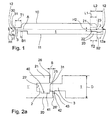
- Fig. 1 the reference numeral 1 shows a panel not according to the invention.
- the extension plane is labeled A.
- the panel 1 has an upper side 10 designed as a visible surface and an underside 11 facing away from this upper side 10. Both sides are connected to each other via end faces 12. At least one of these end faces 12 is provided with a spring 3 and the end face 12 opposite this end face 12 has a groove 2.
- the groove 2 having the end face as groove side 12 a and the spring. 3 having end face referred to as the spring side 12b.
- the groove 2 is formed by two groove cheeks 20, 21, wherein a first groove cheek 20, in alignment with the underside 11 of the panel 1, and a second groove cheek 21, in alignment with the top 10 of the panel 1, is arranged.
- the first groove cheek 20 has a length L2 which is smaller than the length L1 of the second groove cheek 21.
- the first groove cheek 20 protrudes from the second groove cheek 21.
- the spring 3 is formed.
- the height H1 of the spring 3 corresponds to the height H2 of the groove 2, so that the spring 3 protrudes into the groove 2 as far as possible without play.
- the depth T1 of the spring measured from the groove side 12a of the panel 1 to the end face 30 of the spring 3, is smaller than the depth T2 of the groove 2.
- the spring end face 30 may rest against the groove bottom 22, at least a (small) gap between the spring end face 30 and groove bottom 22.
- This extreme case occurs when, for example, the panel 1 has its greatest extent, so is relatively humid. As soon as the panel 1 has become slightly dryer and shrinks slightly in its extent, there is a certain distance between the groove bottom 22 and the end face 30 of the spring 3. If the panel 1 contracts due to further drying out, the gap between the spring end face 30 and the groove bottom 22 becomes larger. In an arrangement of several panels to each other, the length expansion, which is caused by heat or moisture, extremely affects.
- latching means 40 and latching elements 42 are provided, which connect the individual panels 1 latching with each other.
- the latching means 40 is formed as a recess 41 which is arranged on the lower groove cheek 20.
- the lower groove cheek is to be understood that groove cheek, which is a substructure (not shown) facing.
- a detent 43 is provided as Verrastungselement 42.
- the width B1 of the locking lug 43 is substantially smaller than the width B2 of the recess 41, so that in the case of shrinkage of the material of the panels 1, the relative position of the latching lug 43 in the recess 41 is changed. The position of the individual panel 1 relative to the substructure is maintained despite shrinkage. The shrinkage is stopped by the interaction of latching means 40 and latching element 42.
- the latching connection causes a panel 1 to attract the other panel 1.
- a slight displacement movement of the individual panel 1 relative to the substructure is possible, so that the shrinkage of the individual panel 1 does not affect the entire panel arrangement.
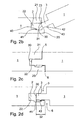
- FIG. 2a to 2d different positions of two panels 1 according to the invention are shown to each other.
- Fig. 2a shows the position of two panels 1, which are not yet locked together.
- the ratio of the supernatant S to the thickness D is approximately 14% in this embodiment. In Fig. 5 this ratio is only about 4%.
- Fig. 2b It is shown how the panels 1 are connected or detached from each other. This is done by a pivoting and sliding movement, which is facilitated by the rounding of groove edges 23 and the spring edge 31.
- the rounded groove edge 23 is arranged on the groove cheek, which is opposite to the groove cheek, which is provided with the latching element 42. According to the illustrated embodiment, the rounded edge of the groove 23 is arranged on the upper groove cheek 21 in the plane of the drawing, this rounded groove edge facing the groove 2 or the spring 3 to be inserted.
- the remaining groove edges can also be rounded. However, this is not essential to the invention.
- the spring 3 is inserted into the groove 2 by the pivoting and sliding movement.
- at least one of the spring edges is also rounded.
- This rounded spring edge 31 faces the rounded groove edge 23 or is arranged on the spring side, which faces away from the latching means 40. If the panels 1 laid in a plane, they can not be separated from each other by a linear movement, a release causes a combined sliding-pivoting movement.
- Fig. 2c a first end position, in which the formed as visible surfaces tops 10 are close to each other.
- the width of the gap 5 goes to zero.
- a gap 6 may remain in this end position, but this can also go to zero.
- the detent 43 is offset from the recess 41 in the image direction to the left.
- Groove bottom 22 and end face 30 of the spring 3 are also slightly spaced from each other in the end position according to this embodiment.
- Fig. 2d the two panels 1 are shown in the second end position.
- the material of both panels 1 has disappeared and the gaps 5 and 6 between the upper and lower sides 10, 11 of the panels 1 have increased.
- the size of the column 5 and 6 are limited by the fact that the locking connection between detent 43 and recess 41 engages.
- the detent 43 is now on the edge of the recess 41.
- Another loss of the panel 1 causes the one panel pulls the other panel by the latching connection.
- the gap 5, 6 between the individual panels is not larger, but the panels 1 are pulled towards the center, so that the gap between the edge of the surface to be laid and the panel assembly is increased.
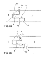
- the recess 41 is disposed in the lower groove cheek 20 such that it is covered by the upper groove cheek 21. Nevertheless, the lower groove cheek 20 is formed longer than the upper groove cheek 21st
- the lower groove cheek 20 is formed substantially longer than the upper groove cheek 21, wherein the recess 41 against the invention in a range is arranged, which is no longer surmounted by the upper groove cheek.
- This measure facilitates the joining of two panels 1 with each other, however, the advantages of a latching connection, are compensated in the length expansions preserved. Again, a rounding of the groove-cheek edges and feather edges is advantageous, but not necessary.
- the configuration of the detent 43 by a bevel in the direction of the end face 30 of the spring 3 is made possible that the collapse of two panels 1 is simplified.
- the groove cheeks 20, 21 are resilient and by the mating the groove cheeks 20, 21 are slightly spread apart. After inserting the spring 3 they spring back into their starting position. The fact that the detent 43 is formed straight on the other side, it hooks with the side wall of the recess 41. The latching connection is thus safe.
- FIG. 4 schematically another variant of the panel assembly according to the invention is shown.
- FIG. 5 an enlarged view is shown, for the sake of clarity, the middle wooden panel 1 is shown extremely shortened, so as to show the installation situation or connection situation of the middle wooden panel 1 with the right wooden panel 1 ".
- the latching means 40 in the groove 2 is formed by a recess 41 in the groove cheek side 24 of the lower, first groove cheek 20, which via a shoulder 44 in the groove bottom 22nd passes. According to the invention, however, this paragraph 44 is not essential, much more important is the groove bottom 22 remote from the recess boundary surface 25, 42 limited in cooperation with the latch 43 of the Verrastungsianas the relative mobility of the two wood panels 1, 1 '. In the process, the groove is delimited by groove shoulder 27 adjoining the depression-limiting surface 25 on the first groove cheek 20.
- the detent 43 is formed by a detent bevel, which begins in the embodiment shown here at the front end of the spring, which then ends with an acute-angled subsequent notch, which cooperates with the latching means 40 (here, for example, the recess boundary surface 25).
- the latching element 42 is in the head portion 32 of the spring 3.
- the latching element 42 is formed as a latching lug 43 which extends to the front end of the head portion 32 and thus optimally utilizes the spring depth.
- the groove shoulder 27 has a width B3 (seen in the direction of insertion of the spring 3 in the groove 2, or in the direction of the groove depth).
- the groove shoulder 27 is bounded on the outside by the Nutwangenstirnseite 26 and inside by the recess limiting surface 25. The surface connecting these two surfaces is part of the groove side wall.
- a chamfer 33 is provided which extends over the entire head portion 32 and in the upper (end) portion of the head portion 32, the height of the spring almost to half the measure reduced.
- the visible side is indicated with 13.
- the panel 1 is inserted in the already mounted wooden panel 1 'from below, such that the slope 33 runs substantially parallel to the groove inner wall.
- the detent 43 engages behind the groove shoulder 27, the panel 1 is folded upwards and brought into a parallel position with respect to the other already mounted panel 1 '.
- the bevel 33 is chosen so that the length M of the chamfer 33 (seen in the insertion or extension plane A) is less than the sum of the width B1 of the detent 43 and the Verrastungsiatas 42 and the width B3 of the groove shoulder 27.
- the invention is provided that the length M of the chamfer 33 is smaller than the sum of the width B1 of the locking lug 43 and the width B3 of the groove shoulder 2 minus the supernatant S.
- the arrangement is also chosen so that the supernatant S is so low that in the in Fig. 5 Einstecksituation shown still straight portion of the spring (in front of the chamfer 33) something in the groove, so behind the Nutwangenstirnseite 26 comes to rest and only here the bend or bevel 33 begins.
- the break point 34 so the transition point of the chamfer 33 to the parallel spring region is a short distance (0.1 or 1 to 2 or 4 mm, or even more) away from the upper groove end.
- the length M, the width B1, the width B3 but also the projection S extend at right angles to the longitudinal extent of the (profile-like) wooden panel 1 and are in the plane of the wooden panel (or a plane parallel thereto).
Landscapes
- Engineering & Computer Science (AREA)
- Architecture (AREA)
- Life Sciences & Earth Sciences (AREA)
- Wood Science & Technology (AREA)
- Civil Engineering (AREA)
- Structural Engineering (AREA)
- Floor Finish (AREA)
- Finishing Walls (AREA)
Claims (15)
- Agencement de panneaux en bois consistant en au moins deux panneaux en bois (1, 1', 1") juxtaposés, liés entre eux et destinés de préférence à recouvrir des murs, plafonds ou planchers, chacun de ces panneaux en bois (1) ayant en particulier une face supérieure (10) prévue pour être une face visible (13) et une face opposée inférieure (11) ainsi que des faces latérales (12, 12a, 12b) reliant la face supérieure (10) à la face inférieure (11), un premier panneau en bois (1') possédant au niveau d'au moins une des ses faces latérales (12, 12a) une rainure (2) et un deuxième panneau en bois (1) possédant au niveau d'au moins une des ses faces latérales (12, 12b) une languette (3), la rainure (2) étant pourvue d'un moyen d'enclenchement (40) et le tenon (3) d'un élément d'enclenchement (42) et, à l'état monté, les positions relatives entre les deux panneaux en bois (1, 1') pouvant être différentes en raison des propriétés de diminution ou d'augmentation des volumes des panneaux (1, 1'), mais permettant un accrochage mutuel entre le moyen d'enclenchement (40) et l'élément d'enclenchement (42) pour au moins une de ces positions lorsque le tenon (3) rentre au moins partiellement dans la rainure (2), le moyen d'enclenchement (40) étant une gorge (41) située à l'intérieur d'au moins une des deux joues (20, 21) de la rainure et l'élément d'enclenchement (42) qui peut être une dent d'enclenchement (43) interagissant avec la gorge (41), caractérisé en ce que l'élément d'enclenchement (42) est situé au niveau de la partie frontale (32) de la languette (3) et en ce que la face de la dent (43) rentrant en premier dans la rainure lors de l'avancement de la languette est inclinée en direction de la face frontale (30) de la languette (3) et est rectiligne au niveau de la face arrière.
- Agencement de panneaux en bois selon la revendication 1, caractérisé en ce que la partie frontale (32) représente au moins la moitié de l'extrémité (T1) de la languette (3) ou en ce que l'agencement est fixé sur un support en laissant en particulier du jeu dans la direction perpendiculaire à la dimension longitudinale du panneau en bois (1) de fagon à ce que les panneaux en bois (1) liés restent mobiles entre eux dans un plan (A) parallèle et/ou perpendiculaire aux faces frontales (12) de la rainure (2) et/ou de la languette (3) et pouvant ainsi se situer à différentes positions relatives et ceci, en particulier en raison d'une réduction dimensionnelle liée à un changement d'hygrométrie.
- Agencement de panneaux en bois selon la revendication 2, caractérisé en ce que la mobilité ou la réduction de volume des panneaux en bois (1) est limitée au moins dans la direction perpendiculaire aux faces frontales (12) de la rainure (2) et/ou de la languette (3) et en particulier par le moyen d'enclenchement (40) et l'élément d'enclenchement (42).
- Agencement de panneaux en bois selon une des revendications précédentes, caractérisé en ce que le moyen d'enclenchement (40) et l'élément d'enclenchement (42) sont orientés perpendiculairement au plan (A) des panneaux en bois (1) ou en ce que le moyen d'enclenchement (40) est situé à l'intérieur des joues de la rainure et, soit au niveau de la joue supérieure (21), soit au niveau de la joue inférieure (20), soit au niveau des joues (20, 21) et en ce que l'élément d'enclenchement (42) est situé au niveau de l'une ou des deux faces latérales de la languette faisant face au joues de rainure (20, 21) ou au moins au niveau de la face latérale de la languette faisant face à la joue de rainure (20, 21) comportant l'élément e (40).
- Agencement de panneaux en bois selon une des revendications précédentes, caractérisé en ce que la gorge (41) située dans la première joue de rainure (20) est délimitée par une face de fond (24) et en ce que qu'un face latérale (25) délimitant latéralement la gorge et faisant face au fond (22) de la rainure est située dans le prolongement de la face frontale (26) de la deuxième joue de rainure (21) ou est située en-dessous de cette ligne de prolongement.
- Agencement de panneaux en bois selon une des revendications précédentes, caractérisé en ce que la gorge (41) possède une forme de rainure et s'étend selon une direction parallèle à la dimension longitudinale des panneaux en bois (1) et/ou en ce que le panneau en bois (1) comporte plusieurs moyens d'enclenchement (40) interagissant avec plusieurs éléments d'enclenchement (42) d'un panneau en bois juxtaposé (1) et/ou en ce que la gorge (41) est plus large que la largeur (B1) de la dent d'enclenchement (43).
- Agencement de panneaux en bois selon une des revendications précédentes, caractérisé en ce que la position de la dent d'enclenchement (43) du premier panneau en bois (1) est ajustable par rapport à la gorge (41) et en fonction de la position relative du deuxième panneau en bois (1) ou en ce que la largeur (T1) de la languette (3) est identique ou inférieure à la profondeur (T2) de la rainure (2).
- Agencement de panneaux en bois selon une des revendications précédentes, caractérisé en ce que les joues (20, 21) de la rainure possède une propriété élastique et/ou en ce qu'une des joues (20, 21) de la rainure et en particulier la joue inférieure (20) dépasse l'autre joue et donc la joue supérieure (21) en créant un dépassement (S) inférieur à la moitié de l'épaisseur (D) du panneau en bois et de préférence inférieur à 40% ou 25% de l'épaisseur (D) du panneau en bois et en particulier inférieur à 10% de l'épaisseur (D) du panneau en bois.
- Agencement de panneaux en bois selon une des revendications précédentes, caractérisé en ce que les joues (20, 21) de la rainure ou au moins une des joues (20) recouvre la languette (3) et ceci, pour toutes les positions relatives entre les deux panneaux en bois (1) et/ou en ce que les joues (20, 21) de la rainure et/ou de la languette (3) possèdent des arêtes (23, 31) dont au moins celles de la rainure (23) et au moins celles de la languette (31) et en particulier les arêtes extérieures sont arrondies et en ce que la joue (21) comportant l'arête arrondie (23) est opposée à la joue (20) comportant le moyen d'enclenchement (40).
- Agencement de panneaux en bois selon la revendication 9, caractérisé en ce que l'arête arrondie (31) de la languette est située sur la face de la languette opposée à celle faisant face à l'élément d'enclenchement (42) et/ou en ce qu'il existe un biseau (33) de la languette située sur la face opposée à celle faisant face à l'élément d'enclenchement (42) etá s'étendant en particulier sur toute la zone frontale (32) de la languette (3).
- Agencement de panneaux en bois selon la revendication 10, caractérisé en ce que la profondeur (M) du biseau (33) est inférieure à la somme de la profondeur (B1) de l'élément d'enclenchement (43) et de la profondeur (B3) de l'extrémité (27) de la joue et en particulier inférieure à la somme de la profondeur (B1) de l'élément d'enclenchement (43) et de la profondeur (B3) de l'extrémité (27) moins le dépassement (S) et/ou en ce que le biseau (33) atteint jusqu'à 80% et de préférence jusqu'à 65% et en particulier jusqu'à 50% de la largeur de la rainure et/ou en ce que les panneaux en bois (1) peuvent être liés entre eux et également désolidarisés par un mouvement de pivotement et de glissement.
- Panneau en bois destiné à un agencement de panneaux en bois selon une des revendications précédentes et comportant des faces latérales (12) reliant les faces supérieure et inférieure (10, 11), une première face latérale (12a) avec une rainure (2) et une deuxième face latérale (12b) avec une languette (3), la rainure (2) étant pourvue d'un moyen d'enclenchement (40) et la languette(3) d'un élément d'enclenchement (42), le moyen d'enclenchement (40) étant une gorge (41) située à l'intérieur d'au moins une des deux joues (20, 21) de la rainure et l'élément d'enclenchement (42) étant une dent d'enclenchement (43) interagissant avec la gorge (41), caractérisé en ce que l'élément d'enclenchement (42) est situé dans la partie frontale (32) de la languette (3) et en ce que la première face de la dent d'enclenchement (43) dans la direction de l'introduction de la languette dans la rainure est inclinée en direction de la face frontale (30) de la languette (3) et rectiligne au niveau de la face arrière.
- Panneau en bois selon la revendication 12, caractérisé en ce que la dent d'enclenchementá (43) possède une largeur (B1) inférieure à celle (B2) de la gorge (41) et/ou en ce que les largeurs (L1, L2) de la première joue (20) et de la deuxième joue (21) formant la rainure (2) sont, soit identiques, soit différentes et/ou en ce que la première joue (20) pourvue du moyen d'enclenchement (40) possède une largeur supérieure à celle de la deuxième joue (21) et/ou en ce que le premier élément d'enclenchement (42) est situé au niveau de la première joue (20) dans une zone qui est partiellement ou totalement couverte par la deuxième joue (21) et/ou en ce que le panneau en bois (1) est formé en un matériau possédant un coefficient thermique élevé et/ou un coefficient d'expansion sous humidité important.
- Panneau en bois selon une des revendications 12 ou 13, caractérisé en ce que la largeur (T1) de la languette (3) est identique ou inférieur à la profondeur (T2) de la rainure (2) et/ou en ce que la languette (3) comporte des arêtes dont au moins une est arrondie (31) ou en particulier chanfreinée (33) au niveau de la partie frontale (32) et/ou en ce que les joues (20, 21) de la rainure comportent des arêtes dont au moins une (23) et de préférence celle proche de la rainure (2) est arrondie ou chanfreinée.
- Panneau en bois selon la revendication 14, caractérisé en ce que l'arête (23) arrondie ou chanfreinée est située au niveau de la joue (20) qui est située en vis-à-vis de la joue (21) comportant le moyen d'enclenchement (40) et en ce que l'arête arrondie (23) fait face à la rainure (2).
Applications Claiming Priority (1)
| Application Number | Priority Date | Filing Date | Title |
|---|---|---|---|
| DE202008015568U DE202008015568U1 (de) | 2008-11-24 | 2008-11-24 | Paneelanordnung und Paneel für die Paneelanordnung |
Publications (2)
| Publication Number | Publication Date |
|---|---|
| EP2189589A1 EP2189589A1 (fr) | 2010-05-26 |
| EP2189589B1 true EP2189589B1 (fr) | 2012-04-18 |
Family
ID=41728091
Family Applications (1)
| Application Number | Title | Priority Date | Filing Date |
|---|---|---|---|
| EP09014606A Not-in-force EP2189589B1 (fr) | 2008-11-24 | 2009-11-24 | Agencement de panneau en bois et panneau en bois pour cet agencement |
Country Status (3)
| Country | Link |
|---|---|
| EP (1) | EP2189589B1 (fr) |
| AT (1) | ATE554244T1 (fr) |
| DE (1) | DE202008015568U1 (fr) |
Families Citing this family (10)
| Publication number | Priority date | Publication date | Assignee | Title |
|---|---|---|---|---|
| GB2477587A (en) * | 2010-07-28 | 2011-08-10 | Architectural Facades And Soffit Systems Ltd | Cladding panels made to resemble tiling |
| DE102011050762A1 (de) * | 2011-05-31 | 2012-12-06 | Guido Schulte | Decken- oder Wandpaneel sowie Verfahren zur Verkleidung eines Decken- oder Wandbereichs |
| DE102011111166A1 (de) * | 2011-08-25 | 2013-02-28 | Johann Krottenthaler | Bodenbelag aus Holz |
| EP2664730A1 (fr) | 2012-05-15 | 2013-11-20 | Falquon GmbH | Panneau pour une pose à plat comme habillage ou revêtement avec une capacité de résistance améliorée contre l'humidité |
| CN102817459B (zh) * | 2012-08-24 | 2015-03-11 | 原大卜 | 实木地板及其安装方法 |
| US10246882B2 (en) | 2015-11-10 | 2019-04-02 | Kong Taing | Structural wall panel system |
| CN108691403A (zh) * | 2017-04-06 | 2018-10-23 | 杨建忠 | 木板块和木地板 |
| CN108868015A (zh) * | 2018-08-10 | 2018-11-23 | 广东铝遊家科技有限公司 | 铝合金构件双钩槽结构 |
| CN110005159A (zh) * | 2019-06-04 | 2019-07-12 | 扬州扬铭新材料有限公司 | 一种便于安装的拼装墙砖及其使用方法 |
| CN110469080A (zh) * | 2019-08-23 | 2019-11-19 | 浙江汇杰力木业有限公司 | 一种地板及其加工方法 |
Family Cites Families (6)
| Publication number | Priority date | Publication date | Assignee | Title |
|---|---|---|---|---|
| FR2205961A5 (fr) * | 1972-11-09 | 1974-05-31 | Plastival Sa | |
| GB2256023A (en) * | 1991-05-18 | 1992-11-25 | Magnet Holdings Ltd | Joint |
| US6588166B2 (en) * | 1995-03-07 | 2003-07-08 | Pergo (Europe) Ab | Flooring panel or wall panel and use thereof |
| DE20205774U1 (de) * | 2002-04-13 | 2002-08-14 | Kronospan Technical Co. Ltd., Nikosia | Paneele mit gummierter Umrandung |
| DE20307580U1 (de) * | 2003-05-15 | 2003-07-10 | Schulte-Führes, Josef, 33102 Paderborn | Fußbodendiele |
| DE102004029233A1 (de) * | 2004-06-17 | 2006-06-08 | Kronospan Technical Co. Ltd., Engomi | Multipositionierbare Wandpaneele |
-
2008
- 2008-11-24 DE DE202008015568U patent/DE202008015568U1/de not_active Expired - Lifetime
-
2009
- 2009-11-24 AT AT09014606T patent/ATE554244T1/de active
- 2009-11-24 EP EP09014606A patent/EP2189589B1/fr not_active Not-in-force
Also Published As
| Publication number | Publication date |
|---|---|
| DE202008015568U1 (de) | 2010-04-15 |
| EP2189589A1 (fr) | 2010-05-26 |
| ATE554244T1 (de) | 2012-05-15 |
Similar Documents
| Publication | Publication Date | Title |
|---|---|---|
| EP1730366B1 (fr) | Panneau pour revêtement | |
| EP2189589A1 (fr) | Agencement de panneau en bois | |
| EP2459818B1 (fr) | Revêtement composé de panneaux mécaniquement reliables entre eux | |
| DE3880737T2 (de) | Verriegelungssystem für Trennwände. | |
| DE10110568C1 (de) | Kabelbrücke | |
| DE102007049792A1 (de) | Verbindung | |
| CH698988B1 (de) | Plattenförmiges Vollholzelement und Abdeckung | |
| EP0652332A1 (fr) | Plaque isolante faite en matériaux isolants thermiques | |
| EP2000610A1 (fr) | Ensemble composé de panneaux en forme tabulaire doté d'un élément de verrouillage mobile | |
| DE102007020271A1 (de) | Verbindung für Fußbodenelemente | |
| EP4230881B1 (fr) | Elément de liaison | |
| AT12597U1 (de) | Steckverbindung | |
| WO2010102735A1 (fr) | Panneau | |
| EP2112297B1 (fr) | Système d'assemblage pour panneaux de plancher | |
| DE202004003393U1 (de) | Schnellbau-Fertigwandmodule | |
| EP2995747B1 (fr) | Liaison mecanique pour panneaux et procede de montage d'une languette de verrouillage dans un panneau | |
| DE202008005295U1 (de) | Verbindung | |
| EP3420158B1 (fr) | Système pour encliqueter deux panneaux de sol | |
| DE10204991C1 (de) | Parkettelement, vorzugsweise aus Holz | |
| DE19846577C2 (de) | Elektrisches Gerät mit einem Verbindungsclip und einer Verbindungsclipaufnahme zur Verbindung mit einem zweiten elektrischen Gerät | |
| DE10253236B4 (de) | Fussbodenpaneel und Verfahren zum Verlegen eines Fussbodenpaneels | |
| DE202007018573U1 (de) | Verbindung | |
| DE20200268U1 (de) | Paneelelement | |
| EP2594704B1 (fr) | Agencement des lames de bois massif | |
| DE202019103487U1 (de) | Spreizbarer Eckwinkel |
Legal Events
| Date | Code | Title | Description |
|---|---|---|---|
| PUAI | Public reference made under article 153(3) epc to a published international application that has entered the european phase |
Free format text: ORIGINAL CODE: 0009012 |
|
| AK | Designated contracting states |
Kind code of ref document: A1 Designated state(s): AT BE BG CH CY CZ DE DK EE ES FI FR GB GR HR HU IE IS IT LI LT LU LV MC MK MT NL NO PL PT RO SE SI SK SM TR |
|
| AX | Request for extension of the european patent |
Extension state: AL BA RS |
|
| 17P | Request for examination filed |
Effective date: 20101001 |
|
| 17Q | First examination report despatched |
Effective date: 20101222 |
|
| GRAP | Despatch of communication of intention to grant a patent |
Free format text: ORIGINAL CODE: EPIDOSNIGR1 |
|
| RTI1 | Title (correction) |
Free format text: WOOD PANEL ASSEMBLY AND WOOD PANEL FOR THIS ASSEMBLY |
|
| GRAS | Grant fee paid |
Free format text: ORIGINAL CODE: EPIDOSNIGR3 |
|
| GRAA | (expected) grant |
Free format text: ORIGINAL CODE: 0009210 |
|
| AK | Designated contracting states |
Kind code of ref document: B1 Designated state(s): AT BE BG CH CY CZ DE DK EE ES FI FR GB GR HR HU IE IS IT LI LT LU LV MC MK MT NL NO PL PT RO SE SI SK SM TR |
|
| REG | Reference to a national code |
Ref country code: GB Ref legal event code: FG4D Free format text: NOT ENGLISH |
|
| REG | Reference to a national code |
Ref country code: CH Ref legal event code: EP |
|
| REG | Reference to a national code |
Ref country code: IE Ref legal event code: FG4D Free format text: LANGUAGE OF EP DOCUMENT: GERMAN |
|
| REG | Reference to a national code |
Ref country code: AT Ref legal event code: REF Ref document number: 554244 Country of ref document: AT Kind code of ref document: T Effective date: 20120515 |
|
| REG | Reference to a national code |
Ref country code: DE Ref legal event code: R096 Ref document number: 502009003264 Country of ref document: DE Effective date: 20120614 |
|
| REG | Reference to a national code |
Ref country code: CH Ref legal event code: NV Representative=s name: ALDO ROEMPLER PATENTANWALT |
|
| REG | Reference to a national code |
Ref country code: NL Ref legal event code: VDEP Effective date: 20120418 |
|
| LTIE | Lt: invalidation of european patent or patent extension |
Effective date: 20120418 |
|
| PG25 | Lapsed in a contracting state [announced via postgrant information from national office to epo] |
Ref country code: FI Free format text: LAPSE BECAUSE OF FAILURE TO SUBMIT A TRANSLATION OF THE DESCRIPTION OR TO PAY THE FEE WITHIN THE PRESCRIBED TIME-LIMIT Effective date: 20120418 Ref country code: CY Free format text: LAPSE BECAUSE OF FAILURE TO SUBMIT A TRANSLATION OF THE DESCRIPTION OR TO PAY THE FEE WITHIN THE PRESCRIBED TIME-LIMIT Effective date: 20120418 Ref country code: LT Free format text: LAPSE BECAUSE OF FAILURE TO SUBMIT A TRANSLATION OF THE DESCRIPTION OR TO PAY THE FEE WITHIN THE PRESCRIBED TIME-LIMIT Effective date: 20120418 Ref country code: IS Free format text: LAPSE BECAUSE OF FAILURE TO SUBMIT A TRANSLATION OF THE DESCRIPTION OR TO PAY THE FEE WITHIN THE PRESCRIBED TIME-LIMIT Effective date: 20120818 Ref country code: SE Free format text: LAPSE BECAUSE OF FAILURE TO SUBMIT A TRANSLATION OF THE DESCRIPTION OR TO PAY THE FEE WITHIN THE PRESCRIBED TIME-LIMIT Effective date: 20120418 Ref country code: NO Free format text: LAPSE BECAUSE OF FAILURE TO SUBMIT A TRANSLATION OF THE DESCRIPTION OR TO PAY THE FEE WITHIN THE PRESCRIBED TIME-LIMIT Effective date: 20120718 Ref country code: PL Free format text: LAPSE BECAUSE OF FAILURE TO SUBMIT A TRANSLATION OF THE DESCRIPTION OR TO PAY THE FEE WITHIN THE PRESCRIBED TIME-LIMIT Effective date: 20120418 |
|
| PG25 | Lapsed in a contracting state [announced via postgrant information from national office to epo] |
Ref country code: PT Free format text: LAPSE BECAUSE OF FAILURE TO SUBMIT A TRANSLATION OF THE DESCRIPTION OR TO PAY THE FEE WITHIN THE PRESCRIBED TIME-LIMIT Effective date: 20120820 Ref country code: SI Free format text: LAPSE BECAUSE OF FAILURE TO SUBMIT A TRANSLATION OF THE DESCRIPTION OR TO PAY THE FEE WITHIN THE PRESCRIBED TIME-LIMIT Effective date: 20120418 Ref country code: GR Free format text: LAPSE BECAUSE OF FAILURE TO SUBMIT A TRANSLATION OF THE DESCRIPTION OR TO PAY THE FEE WITHIN THE PRESCRIBED TIME-LIMIT Effective date: 20120719 Ref country code: HR Free format text: LAPSE BECAUSE OF FAILURE TO SUBMIT A TRANSLATION OF THE DESCRIPTION OR TO PAY THE FEE WITHIN THE PRESCRIBED TIME-LIMIT Effective date: 20120418 Ref country code: LV Free format text: LAPSE BECAUSE OF FAILURE TO SUBMIT A TRANSLATION OF THE DESCRIPTION OR TO PAY THE FEE WITHIN THE PRESCRIBED TIME-LIMIT Effective date: 20120418 |
|
| PG25 | Lapsed in a contracting state [announced via postgrant information from national office to epo] |
Ref country code: RO Free format text: LAPSE BECAUSE OF FAILURE TO SUBMIT A TRANSLATION OF THE DESCRIPTION OR TO PAY THE FEE WITHIN THE PRESCRIBED TIME-LIMIT Effective date: 20120418 Ref country code: DK Free format text: LAPSE BECAUSE OF FAILURE TO SUBMIT A TRANSLATION OF THE DESCRIPTION OR TO PAY THE FEE WITHIN THE PRESCRIBED TIME-LIMIT Effective date: 20120418 Ref country code: EE Free format text: LAPSE BECAUSE OF FAILURE TO SUBMIT A TRANSLATION OF THE DESCRIPTION OR TO PAY THE FEE WITHIN THE PRESCRIBED TIME-LIMIT Effective date: 20120418 Ref country code: CZ Free format text: LAPSE BECAUSE OF FAILURE TO SUBMIT A TRANSLATION OF THE DESCRIPTION OR TO PAY THE FEE WITHIN THE PRESCRIBED TIME-LIMIT Effective date: 20120418 Ref country code: SK Free format text: LAPSE BECAUSE OF FAILURE TO SUBMIT A TRANSLATION OF THE DESCRIPTION OR TO PAY THE FEE WITHIN THE PRESCRIBED TIME-LIMIT Effective date: 20120418 Ref country code: NL Free format text: LAPSE BECAUSE OF FAILURE TO SUBMIT A TRANSLATION OF THE DESCRIPTION OR TO PAY THE FEE WITHIN THE PRESCRIBED TIME-LIMIT Effective date: 20120418 |
|
| PLBE | No opposition filed within time limit |
Free format text: ORIGINAL CODE: 0009261 |
|
| STAA | Information on the status of an ep patent application or granted ep patent |
Free format text: STATUS: NO OPPOSITION FILED WITHIN TIME LIMIT |
|
| PG25 | Lapsed in a contracting state [announced via postgrant information from national office to epo] |
Ref country code: IT Free format text: LAPSE BECAUSE OF FAILURE TO SUBMIT A TRANSLATION OF THE DESCRIPTION OR TO PAY THE FEE WITHIN THE PRESCRIBED TIME-LIMIT Effective date: 20120418 |
|
| 26N | No opposition filed |
Effective date: 20130121 |
|
| PG25 | Lapsed in a contracting state [announced via postgrant information from national office to epo] |
Ref country code: ES Free format text: LAPSE BECAUSE OF FAILURE TO SUBMIT A TRANSLATION OF THE DESCRIPTION OR TO PAY THE FEE WITHIN THE PRESCRIBED TIME-LIMIT Effective date: 20120729 |
|
| REG | Reference to a national code |
Ref country code: DE Ref legal event code: R097 Ref document number: 502009003264 Country of ref document: DE Effective date: 20130121 |
|
| BERE | Be: lapsed |
Owner name: SCHENK, GERHARD Effective date: 20121130 |
|
| PG25 | Lapsed in a contracting state [announced via postgrant information from national office to epo] |
Ref country code: BG Free format text: LAPSE BECAUSE OF FAILURE TO SUBMIT A TRANSLATION OF THE DESCRIPTION OR TO PAY THE FEE WITHIN THE PRESCRIBED TIME-LIMIT Effective date: 20120718 |
|
| REG | Reference to a national code |
Ref country code: IE Ref legal event code: MM4A |
|
| PG25 | Lapsed in a contracting state [announced via postgrant information from national office to epo] |
Ref country code: BE Free format text: LAPSE BECAUSE OF NON-PAYMENT OF DUE FEES Effective date: 20121130 |
|
| PG25 | Lapsed in a contracting state [announced via postgrant information from national office to epo] |
Ref country code: IE Free format text: LAPSE BECAUSE OF NON-PAYMENT OF DUE FEES Effective date: 20121124 |
|
| PG25 | Lapsed in a contracting state [announced via postgrant information from national office to epo] |
Ref country code: MT Free format text: LAPSE BECAUSE OF FAILURE TO SUBMIT A TRANSLATION OF THE DESCRIPTION OR TO PAY THE FEE WITHIN THE PRESCRIBED TIME-LIMIT Effective date: 20120418 |
|
| PG25 | Lapsed in a contracting state [announced via postgrant information from national office to epo] |
Ref country code: MC Free format text: LAPSE BECAUSE OF NON-PAYMENT OF DUE FEES Effective date: 20121130 Ref country code: TR Free format text: LAPSE BECAUSE OF FAILURE TO SUBMIT A TRANSLATION OF THE DESCRIPTION OR TO PAY THE FEE WITHIN THE PRESCRIBED TIME-LIMIT Effective date: 20120418 |
|
| PG25 | Lapsed in a contracting state [announced via postgrant information from national office to epo] |
Ref country code: SM Free format text: LAPSE BECAUSE OF FAILURE TO SUBMIT A TRANSLATION OF THE DESCRIPTION OR TO PAY THE FEE WITHIN THE PRESCRIBED TIME-LIMIT Effective date: 20120418 Ref country code: LU Free format text: LAPSE BECAUSE OF NON-PAYMENT OF DUE FEES Effective date: 20121124 |
|
| GBPC | Gb: european patent ceased through non-payment of renewal fee |
Effective date: 20131124 |
|
| PG25 | Lapsed in a contracting state [announced via postgrant information from national office to epo] |
Ref country code: HU Free format text: LAPSE BECAUSE OF FAILURE TO SUBMIT A TRANSLATION OF THE DESCRIPTION OR TO PAY THE FEE WITHIN THE PRESCRIBED TIME-LIMIT Effective date: 20091124 |
|
| PG25 | Lapsed in a contracting state [announced via postgrant information from national office to epo] |
Ref country code: GB Free format text: LAPSE BECAUSE OF NON-PAYMENT OF DUE FEES Effective date: 20131124 |
|
| PGFP | Annual fee paid to national office [announced via postgrant information from national office to epo] |
Ref country code: FR Payment date: 20141118 Year of fee payment: 6 |
|
| PGFP | Annual fee paid to national office [announced via postgrant information from national office to epo] |
Ref country code: CH Payment date: 20150121 Year of fee payment: 6 |
|
| PG25 | Lapsed in a contracting state [announced via postgrant information from national office to epo] |
Ref country code: MK Free format text: LAPSE BECAUSE OF FAILURE TO SUBMIT A TRANSLATION OF THE DESCRIPTION OR TO PAY THE FEE WITHIN THE PRESCRIBED TIME-LIMIT Effective date: 20120418 |
|
| PGFP | Annual fee paid to national office [announced via postgrant information from national office to epo] |
Ref country code: AT Payment date: 20151112 Year of fee payment: 7 |
|
| PGFP | Annual fee paid to national office [announced via postgrant information from national office to epo] |
Ref country code: DE Payment date: 20160122 Year of fee payment: 7 |
|
| REG | Reference to a national code |
Ref country code: CH Ref legal event code: PL |
|
| PG25 | Lapsed in a contracting state [announced via postgrant information from national office to epo] |
Ref country code: LI Free format text: LAPSE BECAUSE OF NON-PAYMENT OF DUE FEES Effective date: 20151130 Ref country code: CH Free format text: LAPSE BECAUSE OF NON-PAYMENT OF DUE FEES Effective date: 20151130 |
|
| REG | Reference to a national code |
Ref country code: FR Ref legal event code: ST Effective date: 20160729 |
|
| PG25 | Lapsed in a contracting state [announced via postgrant information from national office to epo] |
Ref country code: FR Free format text: LAPSE BECAUSE OF NON-PAYMENT OF DUE FEES Effective date: 20151130 |
|
| REG | Reference to a national code |
Ref country code: DE Ref legal event code: R119 Ref document number: 502009003264 Country of ref document: DE |
|
| REG | Reference to a national code |
Ref country code: AT Ref legal event code: MM01 Ref document number: 554244 Country of ref document: AT Kind code of ref document: T Effective date: 20161124 |
|
| PG25 | Lapsed in a contracting state [announced via postgrant information from national office to epo] |
Ref country code: AT Free format text: LAPSE BECAUSE OF NON-PAYMENT OF DUE FEES Effective date: 20161124 |
|
| PG25 | Lapsed in a contracting state [announced via postgrant information from national office to epo] |
Ref country code: DE Free format text: LAPSE BECAUSE OF NON-PAYMENT OF DUE FEES Effective date: 20170601 |