EP2189594B1 - Dispositif d'appui de parapet, agencement d'appui de parapet et protection contre la chute - Google Patents
Dispositif d'appui de parapet, agencement d'appui de parapet et protection contre la chute Download PDFInfo
- Publication number
- EP2189594B1 EP2189594B1 EP09175653A EP09175653A EP2189594B1 EP 2189594 B1 EP2189594 B1 EP 2189594B1 EP 09175653 A EP09175653 A EP 09175653A EP 09175653 A EP09175653 A EP 09175653A EP 2189594 B1 EP2189594 B1 EP 2189594B1
- Authority
- EP
- European Patent Office
- Prior art keywords
- railing
- elements
- support
- supporting
- wall
- Prior art date
- Legal status (The legal status is an assumption and is not a legal conclusion. Google has not performed a legal analysis and makes no representation as to the accuracy of the status listed.)
- Active
Links
- 125000006850 spacer group Chemical group 0.000 claims abstract description 30
- 238000009434 installation Methods 0.000 claims description 7
- 240000006829 Ficus sundaica Species 0.000 description 3
- 230000000712 assembly Effects 0.000 description 2
- 238000000429 assembly Methods 0.000 description 2
- 239000011449 brick Substances 0.000 description 2
- 238000010276 construction Methods 0.000 description 2
- 239000011810 insulating material Substances 0.000 description 2
- 239000011505 plaster Substances 0.000 description 2
- 230000000903 blocking effect Effects 0.000 description 1
- 239000004568 cement Substances 0.000 description 1
- 230000001419 dependent effect Effects 0.000 description 1
- 239000000835 fiber Substances 0.000 description 1
- 230000001771 impaired effect Effects 0.000 description 1
- 238000007373 indentation Methods 0.000 description 1
- 238000009413 insulation Methods 0.000 description 1
- 239000002184 metal Substances 0.000 description 1
- 230000002093 peripheral effect Effects 0.000 description 1
- 239000007787 solid Substances 0.000 description 1
- 239000002023 wood Substances 0.000 description 1
Images

Classifications
-
- E—FIXED CONSTRUCTIONS
- E04—BUILDING
- E04G—SCAFFOLDING; FORMS; SHUTTERING; BUILDING IMPLEMENTS OR AIDS, OR THEIR USE; HANDLING BUILDING MATERIALS ON THE SITE; REPAIRING, BREAKING-UP OR OTHER WORK ON EXISTING BUILDINGS
- E04G21/00—Preparing, conveying, or working-up building materials or building elements in situ; Other devices or measures for constructional work
- E04G21/32—Safety or protective measures for persons during the construction of buildings
- E04G21/3204—Safety or protective measures for persons during the construction of buildings against falling down
- E04G21/3219—Means supported by the building wall, e.g. security consoles
-
- E—FIXED CONSTRUCTIONS
- E04—BUILDING
- E04F—FINISHING WORK ON BUILDINGS, e.g. STAIRS, FLOORS
- E04F11/00—Stairways, ramps, or like structures; Balustrades; Handrails
- E04F11/18—Balustrades; Handrails
- E04F11/181—Balustrades
- E04F11/1812—Details of anchoring to the wall or floor
Definitions
- the invention relates to a railing support device for mounting a fall protection on a particular vertical wall and a fall protection.
- Guardrail support devices are usually needed to provide fall protection for people working there especially on elevated workplaces. Especially on building roofs accidents can be avoided.
- the known devices are either designed so that they are in the work area, ie z. B. on the roof, must be attached. As a result, the work area is not freely accessible for the intended work. Or else, the devices must be supported against the facade, which leads to their damage especially in already existing, so finished facades. That is, known devices can only be applied to new buildings, in which a fortification still on the bare masonry, z. B. is possible directly on the brick.
- An essential point of the invention is that by means of the railing support device according to the invention now fall protection, but also other work aids can be attached without damaging facades and / or affect the work area. This is particularly advantageous in the case of facades whose outer layer (eg plaster, underlying insulating material, etc.) must not be damaged or in which projections (for example, roof porches, etc.) prevent the support element from contacting the wall.
- outer layer eg plaster, underlying insulating material, etc.
- projections for example, roof porches, etc.
- the device according to the invention is applicable to a wide variety of circumstances (various types of facades, such as wood facades, concrete facades, brick facades, aerated concrete, thermal insulation system facades (ETICS), clad facades (eg metal facades, fiber cement panels), Attica types, especially in existing buildings), on the one hand the secure attachment of Railing support device is not accomplished by means of a support against the wall and on the other hand, any distance of the support element and thus the railing support device is adjustable to the wall. In addition, no structural parts for attachment of the railing support device are provided on or on the actual work area and the resulting work can be carried out freely.
- various types of facades such as wood facades, concrete facades, brick facades, aerated concrete, thermal insulation system facades (ETICS), clad facades (eg metal facades, fiber cement panels), Attica types, especially in existing buildings
- EICS thermal insulation system facades
- clad facades eg metal facades, fiber cement panels
- Attica types especially in existing
- the railing support device is to be understood as a kind of railing post element with which ultimately a complete railing can be mounted at the desired location.
- the railing is mounted by means of several rail support devices, the railing support devices are arranged for this purpose at certain distances from each other.
- Off-road support or fall protection are temporarily created or mounted facilities and can easily after completion of the work again be removed.
- the facilities can also be combined with any type of scaffolding.
- the through holes are preferably positioned at one end region of the support device, so that the other end region is available for receiving the work aid.
- the railing support device is designed such that it can be attached to the facade on a building. Especially in buildings, it is often necessary to increase jobs, such. B. to secure the roof area (especially flat roofs) against falling. The facade side attachment in no way affects the work area, while still providing safe protection against accidents.
- a side guard can be mounted as a "drop stop" or the device allows the inclusion of a railing support to mount a complete fall protection around the work area around.
- the railing support device according to the invention not only allows the attachment of a complete fall protection, so a railing. Rather, other types of work aids, such.
- a tread area As a tread area, a storage area for tools or the like auxiliaries, are mounted with the new device.
- each of the fastening elements has a first threaded area at a first end, so that the respective fastening element can be screwed into the wall.
- a suitable dowel element as a secure attachment of the fastener or fasteners is guaranteed in the wall.
- the fasteners are usually fastened to one another in the wall for mounting the railing support device. Via the through holes in the support element, this is pushed onto the fastening elements (via the second end of the fastening elements) and subsequently with the wall-inner spacer elements and fixed to the outer support members on the fasteners in the desired position.
- each of the fastening elements and the respective spacer element and the respective retaining element are designed such that the spacer element and the retaining element are displaceably guided on the respective fastening element and can be fixed to a defined or desired position and thus the distance of the support element to the wall is adjustable.
- the support element can be fastened with different distances to the wall or facade, depending on the type of facade (for example, with a distance of 3 m).
- the outside of the façade eg plaster, insulating material
- the multiple attachment of the support element via the fastening elements offers great security without having to support the support element on the wall.
- the spacer elements and the holding elements are formed as nuts (nut, lock nut, which brace against each other), which are feasible and fixable via a second threaded portion of the respective fastener.
- the support member is, as stated above, held between the spacer elements and the support members by this on the fasteners, in principle so clamped between the support members.
- the nuts are screwed onto the thread of the respective fastener.
- the spacers that fix the support member on the side facing the wall define the distance that the support member should have to the wall. In order to keep the leverage at a load of the support element low, the distance to the wall can be kept as low as possible.
- the outer holding elements then fix the support element on the outer side of the support element, which faces away from the wall. Thus, the support element between each of the spacer elements and the retaining elements is securely clamped.
- the spacers and the holding elements at the desired positions on the Fixing elements set and the distance of the support member to the wall or the facade can be set as desired and possibly also changed.
- a separate threaded area can be provided here, or else the threaded area extends over the entire second end of the respective fastening element. This positioning of the support element is infinitely possible at any point on the fasteners.
- the spacing elements and the holding elements are designed as wedging elements or the like fixing devices, which can be fastened to the respective fastening element, in particular via a latching mechanism.
- different positions for the support element can be defined, continuously or in defined latching sections.
- the spacer elements are formed as nuts and the holding elements as wedging or the like fixing devices or the holding elements are as nuts and the spacer elements are formed as Verkeilungsiana or the like fixing devices. That is, a combination of nuts and other retaining elements is possible.
- the spacing elements can be designed as disk elements or the like fixable in the respective fastening elements. These can then interact with any holding elements.
- Anchorable, for example latchable disc elements allow rapid installation of the railing support device.
- Firmly anchorable disc elements can in principle also be used as holding elements.
- the nuts can be fixed and secured by pinning on the respective fastener.
- z. B. slot or hole areas provided.
- the first threaded portion for screwing a fastener into the wall may be integrally formed with the second threaded portion or the second threaded portions, i. h.,
- the threaded portion extends over the entire respective fastener. This simplifies the production of the fasteners. For different thread areas these can be different and therefore optimally designed for different conditions (screwing into the wall, carrying spacers and holding elements).
- each of the fastening elements in each case has at least one engagement region, so that the fastening element, in particular by means of an auxiliary tool in the wall fastened, in particular in the wall can be screwed. This facilitates the mounting of the fasteners.
- the attack area can z. B. may be provided as a slot on the front side, in the use of the fastener facing away from the wall second end, have an attack area for an Allen wrench or provide a peripheral around the respective fastener attack area for a wrench.
- the support element or the railing support device for receiving a railing support is formed.
- the support element comprises at least one mounting hole, preferably a plurality of mounting holes as further through holes for receiving the railing support.
- the fastened support element extends upwards on the wall, that is to say in the vertical direction, so that the railing support, which is designed as a tube for this purpose, can be plugged and clamped to the support element.
- the support element thus serves as a support for the railing support.
- the mounting holes are preferably arranged one above the other in a direction of extension of the support element, spaced from each other, and are z. B. such that they can be aligned with corresponding holes in the railing support aligned.
- About a drop plug or the like fixing the railing support can now be set or added to the support element in the desired height. For example, different heights can be provided for the railing support.
- the railing support is also a hole or mounting hole area is sufficient, or can be brought into coincidence with any mounting hole of the support element.
- the fixing element can then be guided through the mounting hole area and the mounting hole and the railing support can be fastened at any height (depending on the selected mounting hole of the support element) or in different positions on the support element by means of drop connectors.
- the railing support is thus adjustable in height on the support element.
- the fixing element is arranged on the railing support and designed to cooperate with the at least one mounting hole of the support element.
- the railing support devices may, for. B. be mounted to all facades of a building, so as to completely surround a roof area with a railing or other work aids such. B. a tread, to install. These tools can then be easily removed after the necessary construction work again.
- the support element could already be designed in such a way that it receives elements of the side protection, but it is advantageous to provide the railing support for this purpose.
- B. can be plugged and so carries the actual side protection elements.
- the railing support has for this purpose at least one receiving element or fastening means on which the side protection element (rod, board, etc.) can be fastened.
- a plurality of support elements are arranged with rail supports at desired distances from each other. The side protection element or even more then run from railing support to railing support and forms so or form so the railing.
- the railing support can - as already described above - be tubular and is attached to the support element. About the fixing elements, the railing support is attached to the support element.
- the support element and the railing support can thus be variably fastened.
- the support element can be fastened in different positions in the "horizontal" direction (with respect to the facade) via spacer elements and retaining elements, and the railing support can in turn be fastened to the support element in "vertical" directions in different positions.
- a railing support assembly comprising a railing support apparatus as described above and a railing support adapted for placement on the railing support apparatus.
- Support element and railing support can be designed so that the railing support is pushed as a tubular member at least partially over the support member or that the railing support, also at least partially, is received in the support member.
- the support member may be at least partially tubular.
- This arrangement allows -. B. with a variety of balustrade support assemblies - the installation of a complete fall protection by railing elements, such. As the side protection already described, be attached to the railing support assembly.
- railing support assembly can be provided on any length formable fall arrest, in which both the distance to the facade, as well as the height are variably adjustable.
- a fall protection with at least one railing support device of the type described above which further comprises a railing support formed for placing on the railing supporting device and at least one side protection or at least one side protection element, wherein at least the side protection can be fastened via fastening means to the railing support device and / or the railing support or the railing support assembly.
- the fall protection may comprise a scaffold covering, which is designed to enter the work aid or fall protection.
- the fall protection with the railing support device according to the invention or the railing support assembly is easy and safe to install and does not affect the work area.
- the railing support, possibly also the railing support device are designed such that they can absorb elements of the fall protection via their fastening means. These are z. As well as the scaffolding and the elements of the side protection.
- the scaffold decking can serve as a step area and, depending on the scaffolding level, is accessible via stairs or ladders.
- the tread area can also be mounted over other elements of a scaffolding structure.
- the side protection (or its elements) is usually formed of railing spars, intermediate beams and toe boards. Thus, a sufficiently high railing is provided, the spars should not exceed a certain distance from each other.
- Fig. 1 shows an element of the railing support device according to the invention, namely a support member 20 in front view.
- This support element 20 is now intended on a particular vertical wall or facade 60 (s. Fig. 3 ) are attached in such a way that it can be added to a work aid, especially for construction.
- a work aid especially for construction.
- Preferably here is to think of elements of a fall protection, ie, for example, to railings, the increased workplaces, z. As roofs, surrounded to protect the working people.
- a railing support 50 (s. Fig. 3 ), the support member 20 in an upper region on a plurality of through holes or mounting holes 22, via which the railing support can be attached.
- Fig. 2 shows the railing support device 10 in a side view, here, also in Fig. 1 visible, further through holes 21 are provided in a lower region of the support element 20. These through holes 21 serve to receive fastening elements 30 with which the support element 20 can be mounted on the facade.
- Fig. 3 shows the on the wall 60, here an Attiki wall, fixed railing support device 10.
- the support member 20 is mounted on the two fasteners 30 on or in the wall 60.
- the fastening elements 30 have first threaded regions 34 (not explicitly illustrated) at a first end facing the wall, so that the fastening elements 30 can be screwed into the wall 60.
- suitable dowel elements 40 in the wall 60 as a secure attachment of the fastener or fasteners 30 is guaranteed in the wall.
- the dowel elements 40 are shown here in simplified form.
- a wall-internal spacer element 31 and an outer retaining element 33 here in each case two nuts, are screwed to each of the fastening elements 30. These hold the support element 20 at the desired position on the fasteners 30 and thus at a desired distance (if required) to the wall 60th
- the spacing elements 31 and the holding elements 33 can here be moved on further threaded areas 35 (likewise not explicitly drawn in) of the fastening elements 30 to the desired position and thus clamp and fix the supporting element 20 therebetween. As shown, nuts or locknuts form the spacer elements 31 and retaining elements 33 here.
- the support member 20 spaced from the facade 60 to install.
- the Attika wall is here z. B. covered by a roof element 61 which protrudes beyond the facade 60.
- attachment of the support element could not be made now, since commercial devices require the support on the facade for their safe installation.
- the support member 20 can now be attached at any distance d to the facade (of course, also directly adjacent to this).
- the nuts 31, 33 are positioned on the fasteners 30 so as to hold the support member 20 in the desired position.
- a railing support 50 is placed on the support member 20, which is fixed here in a lower through hole of mounting holes 22 of the support member 20 by means of a fixing member 52 (the elements thus form a railing support assembly 2). Due to the large number of mounting holes 22 in the support element 20 and possibly also in the railing support 50, this is height-adjustable on the support element 20 (here, for example, a four-level height compensation is provided).
- the railing support 50 itself has a protruding element 51 on a lower region, in or on which railing boards or similar devices (eg elements of a side protection, not shown here) for forming the railing can be stored as working aids or fall protection. Several elements of this kind for receiving elements of a side guard are possible.
- the fixing element 52 is here z. B. on the railing support 50 is preferably rotatably mounted and engages a hole or a mounting hole portion 53 in the railing support 50 in a mounting hole 22 in the support means 20 a.
- the mounting holes 22 are drawn for clarity with solid instead of dashed lines.
- Fig. 3 So shows the support member 20 together with its attachment (railing support device 10). With the attached railing support 50, the railing support assembly 2 is formed.
- Fig. 4 shows a plan view of the support member 20 with pushed fastener 30th
- the support element can also by other holding elements, such.
- other holding elements such as wedges, pins or similar elements are positioned and fastened.
- Fig. 5 shows a section of the railing support device 10 according to the invention in a further embodiment, wherein the wall-inner spacer element is formed here as a disc member 32.
- the disk element 32 may, for. B. engage a corresponding region of the fastening device 30 and so set the distance d for the support member 20 to the wall 60.
- a nut 33 is provided, which is the support element 20th presses on the disk element 32.
- the nut 33 is movable on the threaded portion 35 of the fastener 30.
- the fasteners 30 are first screwed into the wall 60, then each of the wall-inner spacers 31 or 32 are screwed or attached to the fasteners 30 in the desired position. Now, the support member 20 can be pushed onto the fasteners 30 to the inner wall spacer elements 31, 32 and fixed with the outer support members 33.
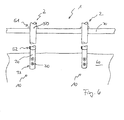
- Fig. 6 shows a crash device according to the invention or fall protection 1, wherein two partial railing support devices 10 and railing support assemblies 2 are shown in detail.
- the two railing support devices 10 show support elements 20 and rail supports 50 placed thereon and are fastened to the wall 60, as described in greater detail above.
- an element of a side guard (eg a railing or intermediate rail) 70 is fastened or mounted.
- a side guard eg a railing or intermediate rail
- only this one detail of the side guard is shown here. In this way, a complete railing can be mounted on a danger area over the railing support devices 10.
- the fall protection can be built up as required from any number of railing support devices or railing support arrangements, which are then connected to each other by means of the side guard.
- the railing support device or railing support assembly according to the invention is in a desired position on a facade, house wall or the like, in particular vertical wall for receiving a work aid attachable, both to new buildings, as well as existing buildings.
- the possibility of spacing the support element from the facade allows its gentle treatment when mounting Fall protection or elements of this fall protection or the like work aids.
Landscapes
- Engineering & Computer Science (AREA)
- Architecture (AREA)
- Civil Engineering (AREA)
- Structural Engineering (AREA)
- Mechanical Engineering (AREA)
- Bridges Or Land Bridges (AREA)
- Refuge Islands, Traffic Blockers, Or Guard Fence (AREA)
- Emergency Lowering Means (AREA)
Claims (18)
- Dispositif d'appui de garde-corps (10) pour le montage d'un dispositif anti-chute (1) sur une paroi (60), en particulier une paroi verticale, comportant :- au moins un élément d'appui (20) à fixer de manière sensiblement verticale pour recevoir des éléments du dispositif anti-chute ou d'au moins un élément du dispositif anti-chute,- au moins deux éléments de fixation (30) pouvant être fixés les uns au-dessus des autres dans la paroi (60) avec des premières extrémités pour fixer l'élément d'appui (20) sur la paroi (60),
dans lequel l'élément d'appui (20) comporte, dans une direction d'extension, au moins deux trous traversants (21) agencés de manière espacée l'un au-dessus de l'autre pour recevoir les éléments de fixation (30),
dans lequel au moins un élément d'écartement (31, 32) interne à la paroi et un élément de retenue extérieur (33) peuvent respectivement être montés sur les éléments de fixation (30) de telle sorte qu'ils serrent l'élément d'appui (20) entre eux mais la distance entre l'élément d'appui (20) et la paroi (60) est réglable. - Dispositif d'appui de garde-corps selon la revendication 1, caractérisé en ce que ce dispositif est conçu de telle sorte qu'il peut être monté sur un bâtiment côté façade.
- Dispositif d'appui de garde-corps selon la revendication 1 ou 2, caractérisé en ce que chacun des éléments de fixation (30) comporte une première zone filetée (34) de telle sorte que l'élément de fixation respectif (30) peut être vissé dans la paroi (60).
- Dispositif d'appui de garde-corps selon l'une quelconque des revendications précédentes, caractérisé en ce que chacun des éléments de fixation (30) et l'élément d'écartement respectif (31, 32) et l'élément de retenue respectif (33) sont conçus de telle sorte que l'élément d'écartement (31, 32) et l'élément de retenue (33) peuvent être guidés de manière mobile et peuvent être fixés sur l'élément de fixation respectif (30) et la distance entre l'élément d'appui (20) et la paroi (60) peut ainsi être réglée.
- Dispositif d'appui de garde-corps selon l'une quelconque des revendications précédentes, caractérisé en ce que les éléments d'écartement (31) et les éléments de retenue (33) sont configurés sous forme d'écrous qui peuvent être guidés et fixés sur l'élément de fixation respectif (30) par l'intermédiaire d'une seconde zone filetée (35).
- Dispositif d'appui de garde-corps selon l'une quelconque des revendications précédentes, en particulier selon l'une quelconque des revendications 1 à 4, caractérisé en ce que les éléments d' écartement et les éléments de retenue sont configurés sous forme d'éléments à clavette ou de moyens de fixation analogues qui peuvent être fixés sur l'élément de fixation respectif, en particulier par l'intermédiaire d'un mécanisme d'encliquetage.
- Dispositif d'appui de garde-corps selon l'une quelconque des revendications précédentes, en particulier selon l'une quelconque des revendications 1 à 4, caractérisé en ce que les éléments d'écartement (31) sont configurés sous forme d'écrous et les éléments de retenue sont configurés sous forme d'éléments à clavette ou de moyens de fixation analogues, ou en ce que les éléments de retenue (33) sont configurés sous forme d'écrous et les éléments d'écartement sont configurés sous forme d'éléments à clavette ou de moyens de fixation analogues.
- Dispositif d'appui de garde-corps selon l'une quelconque des revendications précédentes, caractérisé en ce que les éléments d'écartement sont configurés sous forme d'éléments en rondelle (32) ou de moyens de fixation analogues pouvant être ancrés dans les éléments de fixation respectifs (30).
- Dispositif d'appui de garde-corps selon l'une quelconque des revendications précédentes, caractérisé en ce que les première et seconde zones filetées (34, 35) sont configurées sous la forme d'une zone filetée unique.
- Dispositif d'appui de garde-corps selon l'une quelconque des revendications précédentes, caractérisé en ce que chacun des éléments de fixation (30) comporte respectivement au moins une zone de prise (36, 37) de telle sorte que l'élément de fixation (30) peut être fixé dans la paroi (60), en particulier peut être vissé dans la paroi, en utilisant en particulier un outil auxiliaire.
- Dispositif d'appui de garde-corps selon l'une quelconque des revendications précédentes, caractérisé en ce que l'élément d'appui (20) est configuré sous la forme d'un élément de dispositif anti-chute pour la réception d'un appui de garde-corps (50).
- Dispositif d'appui de garde-corps selon l'une quelconque des revendications précédentes, caractérisé en ce que l'élément d'appui (20) inclut au moins un trou de montage (22) ayant la forme d'un trou traversant supplémentaire pour la réception de l'appui de garde-corps (50).
- Dispositif d'appui de garde-corps selon l'une quelconque des revendications précédentes, caractérisé en ce que l'élément d'appui (20) inclut plusieurs trous de montage (22) qui sont de préférence agencés, dans la direction d'extension de l'élément d'appui (20), de manière espacée les uns au-dessus des autres, de telle sorte l'appui de garde-corps (50) peut être reçu sur l'élément d'appui (20) dans différentes positions et est ainsi réglable en hauteur.
- Dispositif d'appui de garde-corps selon l'une quelconque des revendications précédentes, caractérisé en ce que l'appui de garde-corps (50) comporte au moins une zone de trous de montage (53) qui peut être amenée de manière affleurante au recouvrement avec le au moins un trou de montage (22) de l'élément d'appui (20), de telle sorte que l'appui de garde-corps (50) peut être reçu sur l'élément d'appui (20) au moyen d'un élément de fixation (52).
- Dispositif d'appui de garde-corps selon l'une quelconque des revendications précédentes, caractérisé en ce que l'élément de fixation (52) est agencé sur l'appui de garde-corps (50) et est conçu pour coopérer avec le au moins un trou de montage (22).
- Agencement d'appui de garde-corps comportant un dispositif d'appui de garde-corps (10) selon l'une quelconque des revendications précédentes et un appui de garde-corps (50) conçu pour être placé sur le dispositif d'appui de garde-corps (10).
- Dispositif anti-chute (1) muni d'au moins un dispositif d'appui de garde-corps (10) selon l'une quelconque des revendications précédentes, comportant en outre un appui de garde-corps (50) conçu pour être placé sur le dispositif d'appui de garde-corps (10) et au moins une protection latérale ou au moins un élément de protection latérale (70), dans lequel au moins la protection latérale peut être fixée sur le dispositif d'appui de garde-corps (10) et/ou l'appui de garde-corps (50) par l'intermédiaire de moyens de fixation.
- Dispositif anti-chute (1) selon la revendication 17, caractérisé en ce que ce dispositif inclut une plate-forme d'échafaudage pour accéder au dispositif anti-chute.
Applications Claiming Priority (2)
| Application Number | Priority Date | Filing Date | Title |
|---|---|---|---|
| DE102008058301 | 2008-11-20 | ||
| DE102009019652A DE102009019652A1 (de) | 2008-11-20 | 2009-04-30 | Geländerstützvorrichtung und Absturzsicherung |
Publications (2)
| Publication Number | Publication Date |
|---|---|
| EP2189594A1 EP2189594A1 (fr) | 2010-05-26 |
| EP2189594B1 true EP2189594B1 (fr) | 2012-01-18 |
Family
ID=41572511
Family Applications (1)
| Application Number | Title | Priority Date | Filing Date |
|---|---|---|---|
| EP09175653A Active EP2189594B1 (fr) | 2008-11-20 | 2009-11-11 | Dispositif d'appui de parapet, agencement d'appui de parapet et protection contre la chute |
Country Status (3)
| Country | Link |
|---|---|
| EP (1) | EP2189594B1 (fr) |
| AT (1) | ATE542005T1 (fr) |
| DE (1) | DE102009019652A1 (fr) |
Families Citing this family (2)
| Publication number | Priority date | Publication date | Assignee | Title |
|---|---|---|---|---|
| ES2469343B1 (es) * | 2014-03-31 | 2015-02-25 | Carpinterías Metálicas Spm, S.L. | Barandilla de seguridad para forjados de plantas y escaleras de obras |
| AT524584B1 (de) | 2021-03-09 | 2022-07-15 | Herbert Brodinger | Geländersteher |
Family Cites Families (9)
| Publication number | Priority date | Publication date | Assignee | Title |
|---|---|---|---|---|
| SE341258B (fr) * | 1970-04-23 | 1971-12-20 | Loeoef N | |
| DE3424001A1 (de) * | 1984-06-29 | 1986-01-02 | Wolfgang 7958 Laupheim Baumann | Vorrichtung zum halten eines umfangsseitigen schalbretts einer deckenschalung |
| EP0345213A1 (fr) * | 1988-06-02 | 1989-12-06 | Egco Ag | Balustre |
| CH675270A5 (fr) * | 1989-02-02 | 1990-09-14 | Urbano Paolocci | |
| DE4415827A1 (de) * | 1994-05-05 | 1995-11-09 | Baumann Verwertungs Gmbh | Vorrichtung zum Errichten einer Schutzwand an der Außenseite eines Gebäudes |
| DE19521897A1 (de) * | 1995-06-16 | 1996-12-19 | Jens Steudel | Geländer |
| US6270057B1 (en) * | 1998-12-16 | 2001-08-07 | Centurion Construction Company | Reuseable multi-story building construction guardrail system |
| DE20018961U1 (de) * | 2000-11-07 | 2001-01-04 | Wilhelm Layher Vermögensverwaltungs-GmbH, 74363 Güglingen | Pfosten für ein Absturzsicherungsgeländer |
| WO2006021595A1 (fr) * | 2004-07-16 | 2006-03-02 | Jaime Puig Nadal | Support de barrieres de securite utilisees dans les chantiers |
-
2009
- 2009-04-30 DE DE102009019652A patent/DE102009019652A1/de not_active Withdrawn
- 2009-11-11 EP EP09175653A patent/EP2189594B1/fr active Active
- 2009-11-11 AT AT09175653T patent/ATE542005T1/de active
Also Published As
| Publication number | Publication date |
|---|---|
| ATE542005T1 (de) | 2012-02-15 |
| DE102009019652A1 (de) | 2010-06-02 |
| EP2189594A1 (fr) | 2010-05-26 |
Similar Documents
| Publication | Publication Date | Title |
|---|---|---|
| EP2354368B1 (fr) | Etrier de fixation pour isolations murales | |
| EP3631119B1 (fr) | Plateforme de montage d'équipement d'ascenseur | |
| DE202020104198U1 (de) | Baugerüst | |
| EP4538481B1 (fr) | Dispositif pour la fixation de protections contre les chutes à des échafaudages | |
| WO2002103136A2 (fr) | Echafaudage demontable | |
| EP3712346A1 (fr) | Syst?me d'échafaudage | |
| EP2423409A1 (fr) | Paroi de sécurité | |
| DE3824387C2 (fr) | ||
| EP2267242B1 (fr) | Console d'échange | |
| CH657888A5 (de) | Metallgeruest mit zur sicherung dienenden, eine drahtgeflechtbespannung aufweisenden metallrahmen. | |
| EP2189594A1 (fr) | Dispositif d'appui de parapet, agencement d'appui de parapet et protection contre la chute | |
| AT524849B1 (de) | Montagesystem für Geländer und Absturzsicherungen | |
| DE2407103A1 (de) | Eine arbeitsbuehne aufweisendes leitergeruest | |
| AT396162B (de) | Auf baustellen verwendbare vorrichtung zum anbringen von gelaenderbrettern od. dgl. | |
| DE8806975U1 (de) | Fußbodenplattenvorrichtung | |
| EP3922784A1 (fr) | Dispositif de nivellement et de retrait | |
| EP1997978B1 (fr) | Aide au montage | |
| DE69016041T2 (de) | Hängendes gerüst. | |
| CH676135A5 (en) | Holder for shuttering elements - has support, forming parallel, offset extension of rail fixed below wall top surface | |
| EP3964667B1 (fr) | Garde-corps plein pour un bâtiment | |
| EP2425069B1 (fr) | Dispositif d'aide à la mise à niveau pour des supports en bois/en poutre, notamment de recouvrements de balcon et de terrasse | |
| AT401541B (de) | Befestigungsvorrichtung für ein balkongeländer sowie eine zugehörige holz-balkonbrüstung | |
| DE3120735A1 (de) | Stockwerkstreppe aus trittplatten | |
| DE9420155U1 (de) | FAssadenbekleidung mit horizontalen Halteprofilen | |
| DE202025101964U1 (de) | Absturzschutzkonsole und Absturzsicherung |
Legal Events
| Date | Code | Title | Description |
|---|---|---|---|
| PUAI | Public reference made under article 153(3) epc to a published international application that has entered the european phase |
Free format text: ORIGINAL CODE: 0009012 |
|
| AK | Designated contracting states |
Kind code of ref document: A1 Designated state(s): AT BE BG CH CY CZ DE DK EE ES FI FR GB GR HR HU IE IS IT LI LT LU LV MC MK MT NL NO PL PT RO SE SI SK SM TR |
|
| AX | Request for extension of the european patent |
Extension state: AL BA RS |
|
| 17P | Request for examination filed |
Effective date: 20100625 |
|
| GRAP | Despatch of communication of intention to grant a patent |
Free format text: ORIGINAL CODE: EPIDOSNIGR1 |
|
| GRAS | Grant fee paid |
Free format text: ORIGINAL CODE: EPIDOSNIGR3 |
|
| GRAA | (expected) grant |
Free format text: ORIGINAL CODE: 0009210 |
|
| AK | Designated contracting states |
Kind code of ref document: B1 Designated state(s): AT BE BG CH CY CZ DE DK EE ES FI FR GB GR HR HU IE IS IT LI LT LU LV MC MK MT NL NO PL PT RO SE SI SK SM TR |
|
| AX | Request for extension of the european patent |
Extension state: AL BA RS |
|
| REG | Reference to a national code |
Ref country code: GB Ref legal event code: FG4D Free format text: NOT ENGLISH |
|
| REG | Reference to a national code |
Ref country code: CH Ref legal event code: EP |
|
| REG | Reference to a national code |
Ref country code: IE Ref legal event code: FG4D Free format text: LANGUAGE OF EP DOCUMENT: GERMAN Ref country code: AT Ref legal event code: REF Ref document number: 542005 Country of ref document: AT Kind code of ref document: T Effective date: 20120215 |
|
| REG | Reference to a national code |
Ref country code: DE Ref legal event code: R096 Ref document number: 502009002475 Country of ref document: DE Effective date: 20120322 |
|
| REG | Reference to a national code |
Ref country code: CH Ref legal event code: NV Representative=s name: SERVOPATENT GMBH |
|
| REG | Reference to a national code |
Ref country code: NL Ref legal event code: VDEP Effective date: 20120118 |
|
| LTIE | Lt: invalidation of european patent or patent extension |
Effective date: 20120118 |
|
| PG25 | Lapsed in a contracting state [announced via postgrant information from national office to epo] |
Ref country code: HR Free format text: LAPSE BECAUSE OF FAILURE TO SUBMIT A TRANSLATION OF THE DESCRIPTION OR TO PAY THE FEE WITHIN THE PRESCRIBED TIME-LIMIT Effective date: 20120118 Ref country code: NL Free format text: LAPSE BECAUSE OF FAILURE TO SUBMIT A TRANSLATION OF THE DESCRIPTION OR TO PAY THE FEE WITHIN THE PRESCRIBED TIME-LIMIT Effective date: 20120118 Ref country code: LT Free format text: LAPSE BECAUSE OF FAILURE TO SUBMIT A TRANSLATION OF THE DESCRIPTION OR TO PAY THE FEE WITHIN THE PRESCRIBED TIME-LIMIT Effective date: 20120118 Ref country code: BG Free format text: LAPSE BECAUSE OF FAILURE TO SUBMIT A TRANSLATION OF THE DESCRIPTION OR TO PAY THE FEE WITHIN THE PRESCRIBED TIME-LIMIT Effective date: 20120418 Ref country code: IS Free format text: LAPSE BECAUSE OF FAILURE TO SUBMIT A TRANSLATION OF THE DESCRIPTION OR TO PAY THE FEE WITHIN THE PRESCRIBED TIME-LIMIT Effective date: 20120518 Ref country code: NO Free format text: LAPSE BECAUSE OF FAILURE TO SUBMIT A TRANSLATION OF THE DESCRIPTION OR TO PAY THE FEE WITHIN THE PRESCRIBED TIME-LIMIT Effective date: 20120418 |
|
| REG | Reference to a national code |
Ref country code: IE Ref legal event code: FD4D |
|
| PG25 | Lapsed in a contracting state [announced via postgrant information from national office to epo] |
Ref country code: LV Free format text: LAPSE BECAUSE OF FAILURE TO SUBMIT A TRANSLATION OF THE DESCRIPTION OR TO PAY THE FEE WITHIN THE PRESCRIBED TIME-LIMIT Effective date: 20120118 Ref country code: GR Free format text: LAPSE BECAUSE OF FAILURE TO SUBMIT A TRANSLATION OF THE DESCRIPTION OR TO PAY THE FEE WITHIN THE PRESCRIBED TIME-LIMIT Effective date: 20120419 Ref country code: PL Free format text: LAPSE BECAUSE OF FAILURE TO SUBMIT A TRANSLATION OF THE DESCRIPTION OR TO PAY THE FEE WITHIN THE PRESCRIBED TIME-LIMIT Effective date: 20120118 Ref country code: PT Free format text: LAPSE BECAUSE OF FAILURE TO SUBMIT A TRANSLATION OF THE DESCRIPTION OR TO PAY THE FEE WITHIN THE PRESCRIBED TIME-LIMIT Effective date: 20120518 Ref country code: FI Free format text: LAPSE BECAUSE OF FAILURE TO SUBMIT A TRANSLATION OF THE DESCRIPTION OR TO PAY THE FEE WITHIN THE PRESCRIBED TIME-LIMIT Effective date: 20120118 |
|
| PG25 | Lapsed in a contracting state [announced via postgrant information from national office to epo] |
Ref country code: CY Free format text: LAPSE BECAUSE OF FAILURE TO SUBMIT A TRANSLATION OF THE DESCRIPTION OR TO PAY THE FEE WITHIN THE PRESCRIBED TIME-LIMIT Effective date: 20120118 |
|
| PG25 | Lapsed in a contracting state [announced via postgrant information from national office to epo] |
Ref country code: SE Free format text: LAPSE BECAUSE OF FAILURE TO SUBMIT A TRANSLATION OF THE DESCRIPTION OR TO PAY THE FEE WITHIN THE PRESCRIBED TIME-LIMIT Effective date: 20120118 Ref country code: SI Free format text: LAPSE BECAUSE OF FAILURE TO SUBMIT A TRANSLATION OF THE DESCRIPTION OR TO PAY THE FEE WITHIN THE PRESCRIBED TIME-LIMIT Effective date: 20120118 Ref country code: RO Free format text: LAPSE BECAUSE OF FAILURE TO SUBMIT A TRANSLATION OF THE DESCRIPTION OR TO PAY THE FEE WITHIN THE PRESCRIBED TIME-LIMIT Effective date: 20120118 Ref country code: EE Free format text: LAPSE BECAUSE OF FAILURE TO SUBMIT A TRANSLATION OF THE DESCRIPTION OR TO PAY THE FEE WITHIN THE PRESCRIBED TIME-LIMIT Effective date: 20120118 Ref country code: CZ Free format text: LAPSE BECAUSE OF FAILURE TO SUBMIT A TRANSLATION OF THE DESCRIPTION OR TO PAY THE FEE WITHIN THE PRESCRIBED TIME-LIMIT Effective date: 20120118 Ref country code: DK Free format text: LAPSE BECAUSE OF FAILURE TO SUBMIT A TRANSLATION OF THE DESCRIPTION OR TO PAY THE FEE WITHIN THE PRESCRIBED TIME-LIMIT Effective date: 20120118 Ref country code: IE Free format text: LAPSE BECAUSE OF FAILURE TO SUBMIT A TRANSLATION OF THE DESCRIPTION OR TO PAY THE FEE WITHIN THE PRESCRIBED TIME-LIMIT Effective date: 20120118 |
|
| PLBE | No opposition filed within time limit |
Free format text: ORIGINAL CODE: 0009261 |
|
| STAA | Information on the status of an ep patent application or granted ep patent |
Free format text: STATUS: NO OPPOSITION FILED WITHIN TIME LIMIT |
|
| PG25 | Lapsed in a contracting state [announced via postgrant information from national office to epo] |
Ref country code: SK Free format text: LAPSE BECAUSE OF FAILURE TO SUBMIT A TRANSLATION OF THE DESCRIPTION OR TO PAY THE FEE WITHIN THE PRESCRIBED TIME-LIMIT Effective date: 20120118 Ref country code: IT Free format text: LAPSE BECAUSE OF FAILURE TO SUBMIT A TRANSLATION OF THE DESCRIPTION OR TO PAY THE FEE WITHIN THE PRESCRIBED TIME-LIMIT Effective date: 20120118 |
|
| 26N | No opposition filed |
Effective date: 20121019 |
|
| REG | Reference to a national code |
Ref country code: DE Ref legal event code: R097 Ref document number: 502009002475 Country of ref document: DE Effective date: 20121019 |
|
| PG25 | Lapsed in a contracting state [announced via postgrant information from national office to epo] |
Ref country code: ES Free format text: LAPSE BECAUSE OF FAILURE TO SUBMIT A TRANSLATION OF THE DESCRIPTION OR TO PAY THE FEE WITHIN THE PRESCRIBED TIME-LIMIT Effective date: 20120429 |
|
| BERE | Be: lapsed |
Owner name: BLAMBERGER, KONRAD JUN. Effective date: 20121130 |
|
| REG | Reference to a national code |
Ref country code: FR Ref legal event code: ST Effective date: 20130731 |
|
| PG25 | Lapsed in a contracting state [announced via postgrant information from national office to epo] |
Ref country code: BE Free format text: LAPSE BECAUSE OF NON-PAYMENT OF DUE FEES Effective date: 20121130 |
|
| PG25 | Lapsed in a contracting state [announced via postgrant information from national office to epo] |
Ref country code: MT Free format text: LAPSE BECAUSE OF FAILURE TO SUBMIT A TRANSLATION OF THE DESCRIPTION OR TO PAY THE FEE WITHIN THE PRESCRIBED TIME-LIMIT Effective date: 20120118 Ref country code: FR Free format text: LAPSE BECAUSE OF NON-PAYMENT OF DUE FEES Effective date: 20121130 |
|
| PG25 | Lapsed in a contracting state [announced via postgrant information from national office to epo] |
Ref country code: TR Free format text: LAPSE BECAUSE OF FAILURE TO SUBMIT A TRANSLATION OF THE DESCRIPTION OR TO PAY THE FEE WITHIN THE PRESCRIBED TIME-LIMIT Effective date: 20120118 Ref country code: MC Free format text: LAPSE BECAUSE OF NON-PAYMENT OF DUE FEES Effective date: 20121130 |
|
| PG25 | Lapsed in a contracting state [announced via postgrant information from national office to epo] |
Ref country code: LU Free format text: LAPSE BECAUSE OF NON-PAYMENT OF DUE FEES Effective date: 20121111 Ref country code: SM Free format text: LAPSE BECAUSE OF FAILURE TO SUBMIT A TRANSLATION OF THE DESCRIPTION OR TO PAY THE FEE WITHIN THE PRESCRIBED TIME-LIMIT Effective date: 20120118 |
|
| REG | Reference to a national code |
Ref country code: CH Ref legal event code: PL |
|
| GBPC | Gb: european patent ceased through non-payment of renewal fee |
Effective date: 20131111 |
|
| PG25 | Lapsed in a contracting state [announced via postgrant information from national office to epo] |
Ref country code: HU Free format text: LAPSE BECAUSE OF FAILURE TO SUBMIT A TRANSLATION OF THE DESCRIPTION OR TO PAY THE FEE WITHIN THE PRESCRIBED TIME-LIMIT Effective date: 20091111 Ref country code: LI Free format text: LAPSE BECAUSE OF NON-PAYMENT OF DUE FEES Effective date: 20131130 Ref country code: CH Free format text: LAPSE BECAUSE OF NON-PAYMENT OF DUE FEES Effective date: 20131130 |
|
| PGFP | Annual fee paid to national office [announced via postgrant information from national office to epo] |
Ref country code: DE Payment date: 20140530 Year of fee payment: 5 |
|
| PG25 | Lapsed in a contracting state [announced via postgrant information from national office to epo] |
Ref country code: GB Free format text: LAPSE BECAUSE OF NON-PAYMENT OF DUE FEES Effective date: 20131111 |
|
| REG | Reference to a national code |
Ref country code: DE Ref legal event code: R119 Ref document number: 502009002475 Country of ref document: DE |
|
| PG25 | Lapsed in a contracting state [announced via postgrant information from national office to epo] |
Ref country code: MK Free format text: LAPSE BECAUSE OF FAILURE TO SUBMIT A TRANSLATION OF THE DESCRIPTION OR TO PAY THE FEE WITHIN THE PRESCRIBED TIME-LIMIT Effective date: 20120118 |
|
| PG25 | Lapsed in a contracting state [announced via postgrant information from national office to epo] |
Ref country code: DE Free format text: LAPSE BECAUSE OF NON-PAYMENT OF DUE FEES Effective date: 20150602 |
|
| REG | Reference to a national code |
Ref country code: AT Ref legal event code: MM01 Ref document number: 542005 Country of ref document: AT Kind code of ref document: T Effective date: 20141111 |
|
| PG25 | Lapsed in a contracting state [announced via postgrant information from national office to epo] |
Ref country code: AT Free format text: LAPSE BECAUSE OF NON-PAYMENT OF DUE FEES Effective date: 20141111 |