EP2189691B1 - Armature de verrouillage pour un système de conduite - Google Patents
Armature de verrouillage pour un système de conduite Download PDFInfo
- Publication number
- EP2189691B1 EP2189691B1 EP09013983A EP09013983A EP2189691B1 EP 2189691 B1 EP2189691 B1 EP 2189691B1 EP 09013983 A EP09013983 A EP 09013983A EP 09013983 A EP09013983 A EP 09013983A EP 2189691 B1 EP2189691 B1 EP 2189691B1
- Authority
- EP
- European Patent Office
- Prior art keywords
- valve
- shut
- shutoff
- side facing
- facing towards
- Prior art date
- Legal status (The legal status is an assumption and is not a legal conclusion. Google has not performed a legal analysis and makes no representation as to the accuracy of the status listed.)
- Not-in-force
Links
- 238000007789 sealing Methods 0.000 claims description 36
- 238000011144 upstream manufacturing Methods 0.000 claims description 5
- 230000000295 complement effect Effects 0.000 claims description 2
- 230000006835 compression Effects 0.000 claims 1
- 238000007906 compression Methods 0.000 claims 1
- 230000001419 dependent effect Effects 0.000 description 4
- 238000013461 design Methods 0.000 description 3
- 239000012530 fluid Substances 0.000 description 3
- 238000006073 displacement reaction Methods 0.000 description 2
- 230000000694 effects Effects 0.000 description 2
- 238000000926 separation method Methods 0.000 description 2
- 238000005299 abrasion Methods 0.000 description 1
- 230000004888 barrier function Effects 0.000 description 1
- 230000000903 blocking effect Effects 0.000 description 1
- 238000006243 chemical reaction Methods 0.000 description 1
- 238000005336 cracking Methods 0.000 description 1
- 210000004907 gland Anatomy 0.000 description 1
- 238000010438 heat treatment Methods 0.000 description 1
- 238000009434 installation Methods 0.000 description 1
- 239000007788 liquid Substances 0.000 description 1
- 238000012423 maintenance Methods 0.000 description 1
- 230000004048 modification Effects 0.000 description 1
- 238000012986 modification Methods 0.000 description 1
- 238000012544 monitoring process Methods 0.000 description 1
- 238000012856 packing Methods 0.000 description 1
- 230000008439 repair process Effects 0.000 description 1
Images


Classifications
-
- F—MECHANICAL ENGINEERING; LIGHTING; HEATING; WEAPONS; BLASTING
- F16—ENGINEERING ELEMENTS AND UNITS; GENERAL MEASURES FOR PRODUCING AND MAINTAINING EFFECTIVE FUNCTIONING OF MACHINES OR INSTALLATIONS; THERMAL INSULATION IN GENERAL
- F16K—VALVES; TAPS; COCKS; ACTUATING-FLOATS; DEVICES FOR VENTING OR AERATING
- F16K3/00—Gate valves or sliding valves, i.e. cut-off apparatus with closing members having a sliding movement along the seat for opening and closing
- F16K3/02—Gate valves or sliding valves, i.e. cut-off apparatus with closing members having a sliding movement along the seat for opening and closing with flat sealing faces; Packings therefor
- F16K3/12—Gate valves or sliding valves, i.e. cut-off apparatus with closing members having a sliding movement along the seat for opening and closing with flat sealing faces; Packings therefor with wedge-shaped arrangements of sealing faces
Definitions
- the DE 33 41 123 discloses a gate valve for a piping system with a number of slide plates and sealing surfaces and an axially displaceable poppet, which is provided with sealing surfaces and loaded by springs, wherein the slide plates have bores and wherein the valve cone is acted upon by the pressure of pending in the pipeline medium.
- a gate valve which comprises a housing provided with pipe connections on both sides with a hood and a hood associated with a screw jack bearing, the gate valve allows replacement of the spindle and the spindle bearing in the operation of the piping system by a seat in the hood Is formed sealing means for a closure body.
- the housing interior is connected via gaps between the slide plates and a spindle with a sealed from the valve cone pressure chamber. If the pressure in the housing interior exceeds the operating pressure prevailing on a slide plate, the valve cone lifts off its seating surface and allows so much medium to escape until the overpressure has been reduced.
- shut-off damper In high-energy piping systems, slide valves have always been used as shut-off elements for shutting off fluid flows.
- this type of shut-off damper is placed in a provided around the two shut-off with a seat around each pipe ends around a housing shut-off element for closing perpendicular to the pipe axis between the seats provided for the shut-off that the fluid flow is interrupted and the shut-off downstream pressed against the seat and thereby a Sealing is achieved.
- one-piece wedge and two-piece wedge or parallel plate slides differ essentially only in the way in which, during or after the movement of the shut-off element to the shut-off, which is perpendicular to the tube axis, its movement or that of the plates held by it in the direction of the pipe axis is achieved for sealing on the seats.
- the invention is therefore based on the object to provide a shut-off valve of the type mentioned, the structural elements are designed such that the achievable seat tightness is maintained even during and after the shutdown of high-energy fluid flows, so that the disadvantages of the previous solutions can be avoided.
- This object is achieved in that the achieved in the closed position distance between the actuator and the seating surfaces is designed such that a deformation that exceeds the limits of the elasticity of the sealing elements, is excluded.
- the invention is based on the consideration that one of the main causes of leaks conventional gate valves based on the seat and the seat seal of the shut-off absorb the entire load acting through the flowing medium and the differential pressure on the gate valve forces and thereby locally overloaded and to be damaged.
- the functional separation of the shut-off and sealing components according to the invention can produce a stable seal without the abrasion of the sealing surfaces produced during shut-off under duress.
- the Fig. 1 shows in section the shut-off valve 1 of the pipeline system 2 in the half-open state, so that a medium flowing through the pipe system 2, not shown here medium can flow through the released from the shut-off 6 passage opening of the shut-off valve 1 therethrough.
- the shut-off valve 1 essentially comprises two main structural elements: the slide housing 4, which is fixedly connected to the piping system 2, and the shut-off element 6, which is arranged to be movable in the region of the slide housing 4 and in the exemplary embodiment has a wedge-shaped actuator 8.
- Fig. 2 shows the shut-off 6 in the pipe 2 closing state.
- the threaded rod of the spindle 26 with its associated wedge-shaped actuator 8 is in the lowest achievable, necessary for the complete shut-off position.
- the guide elements 34a and 34b prevent an excessive pressing of the shut-off element 6 against the end or seat surfaces 36 or 38 of the pipeline system 2 which are located in the direction of the resulting pressure force. Without the guide elements 34a and 34b, both when the shut-off element 6 is inserted into the closed position as well as remaining in this closed position, a differential pressure-dependent force both on the seat located in the direction of compressive force seats 36 or 38 and on this side of the actuator 8 arranged to act on the seats 36 and 38 leaning sealing elements 48 or 50 act. This could lead to an excess beyond the elastic limit load and deformation of the sealing elements 48 and 50 and irreversibly damage them.
- sealing elements 48, 50 are mounted.
- elastic sealing rings or ring seals 48, 50 provided with respect to arrangement position and diameter on the them in the Closure state of the gate valve opposite pipe seat ring surfaces, that are tuned to the annular end or seat surfaces 36, 38.
- the nature and geometry of the ring seals 48 and 50, in particular their axial extent and elasticity, in relation to the gap width of the respective annular gap 54 or 56 given in the closure state are selected so that the respective ring seal 48 or 50 in the closed state of the shut-off element 6 with the necessary surface pressure to achieve a sufficient tightness, but if possible not beyond, elastically deformed and compressed. This at the same time an undesirable tension or blocking of the shut-off 6 is excluded in the closed position, which could otherwise be caused by thermal expansion of the valve body or the spindle 26 due to ambient or media-induced temperature transients.
- the (cross-sectional) geometry of the respective ring seal 48, 50 is designed by suitable choice of its inner and outer diameter so that it acts self-sealing with increasing differential pressure in the flow direction of the medium guided in the pipeline system 2.
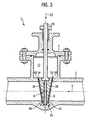
- Fig. 3 is for the guided in the piping system 2 medium a preferred flow direction 3, here flowing from right to left, provided.
- elastic ring seal 50 on the actuator 8 side facing a larger diameter than on the actuator 8 facing away from the seat surface 38 side facing. Seen in section, the annular seal 50 thus bulges inwards, starting from the actuator 8, inwards toward the pipeline axis A and rests there against the annular seating surface 38.
- both ring seals 48, 50 have a larger wedge-side and a smaller seat-side diameter. This ensures that - regardless of the intended flow direction of the medium in the piping system 2 - a in incompressible media (liquids) possibly building up overpressure in the slide dome 10, z. B. by heating trapped in the slide dome 10 volumes, can automatically degrade into the piping system 2.
- the pressure built up in the slider dome 10 counteracts namely the elastic bias of the ring seal 48 and 50 and lifts them from their sealing seat on the seat surface 36 and 38 of the piping system 2 such that under pressure medium standing from the slide dome 10 in the piping system 2 can escape, so that an impermissible pressure in the slide dome 10 is avoided. Additional measures against impermissible housing pressure build-up are therefore not necessary.
Landscapes
- Engineering & Computer Science (AREA)
- General Engineering & Computer Science (AREA)
- Mechanical Engineering (AREA)
- Sliding Valves (AREA)
- Quick-Acting Or Multi-Walled Pipe Joints (AREA)
- Lift Valve (AREA)
Claims (8)
- Dispositif de fermeture (1) pour un système de conduite (2), ayant un boîtier de vanne (4) pourvu des deux côtés de raccords de conduite et ayant un élément de fermeture (6) qui peut être poussé, dans une direction perpendiculaire à l'axe de la conduite (A), dans une position fermée, dans lequel l'élément de fermeture (6) comprend une vanne (8) et un nombre d'éléments d'étanchéité (48, 50) élastiques et dans lequel les raccords de conduite sont pourvus de surfaces d'appui (36, 38) pour l'élément de fermeture (6), dans lequel la distance entre la vanne (8) et les surfaces d'appui (36, 38) atteinte dans la position fermée est dimensionnée de façon à ce qu'une déformation des éléments d'étanchéité (48, 50) excédant les limites d'élasticité de ces derniers est exclue et dans lequel chacun des éléments d'étanchéité (48, 50) de l'élément de fermeture (6) est prévu comme anneau torique d'étanchéité, caractérisé en ce qu'au moins un des anneaux toriques d'étanchéité (48, 50) disposés sur la vanne (8) a, de son côté en regard de la surface d'appui (36, 38) de la conduite, un diamètre plus petit que de son côté en regard de la vanne (8).
- Dispositif de fermeture (1) selon la revendication 1, dans lequel chacun des deux anneaux toriques d'étanchéité (48, 50) disposés sur la vanne (8) a, de son côté en regard de la surface d'appui (36, 38) de la conduite, un diamètre plus petit que de son côté en regard de la vanne. (8).
- Dispositif de fermeture (1) selon la revendication 1, pourvu pour une direction d'écoulement (6) préférée d'un milieu coulant à travers le système de conduite (2), dans lequel l'anneau torique d'étanchéité (50) disposé du côté en amont de la vanne (8) a, de son côté en regard de la surface d'appui (38), un diamètre plus petit que de son côté en regard de la vanne (8) et dans lequel l'anneau torique d'étanchéité (48) disposé du côté en aval de la vanne (8) a, de son côté en regard de la surface d'appui (36), un diamètre plus grand que de son côté en regard de la vanne (8).
- Dispositif de fermeture (1) selon l'une quelconque des revendications 1 à 3, dans lequel la vanne (8) est étudiée en forme de clavette.
- Dispositif de fermeture (1) selon l'une quelconque des revendications 1 à 4, dont la vanne (8) comprend au moins un élément de guidage (34a) auquel un élément de guidage (34b) complémentaire, relié avec le boîtier de vanne (4), est affecté, dans lequel les éléments de guidage (34a, 34b) son conçus de manière qu'un basculement ou un déplacement de la vanne (8) dans la direction de l'axe de la conduite (A) est empêché.
- Dispositif de fermeture (1) selon la revendication 5, dont les éléments de guidage (34a, 34b) son conçus de manière que des forces agissant sur l'élément de fermeture (6) sont dissipées au moyen des éléments de guidage (34a, 34b) dans la direction de l'axe de la conduite (A) vers le boîtier de vanne (4).
- Dispositif de fermeture (1) selon la revendication 5 or 6, dans lequel les éléments de guidage (34a, 34b) du boîtier de vanne (4) comprennent un nombre de listels ou de barres et les éléments de guidage (34a, 34b) de la vanne (8) comprennent un nombre de creux ou de rainures y appartenant.
- Dispositif de fermeture (1) selon l'une quelconque des revendications 1 à 4, dans lequel le chemin de la course de l'élément de fermeture (6) dans la direction de fermeture (52) est limité par une butée fixe, de façon à ce qu'une compression inélastique des éléments d'étanchéité (48, 50) lors du contact avec les surfaces d'appui (36, 38) y appartenant est exclue.
Priority Applications (1)
| Application Number | Priority Date | Filing Date | Title |
|---|---|---|---|
| PL09013983T PL2189691T3 (pl) | 2008-11-25 | 2009-11-06 | Armatura odcinająca dla układu rurociągów |
Applications Claiming Priority (1)
| Application Number | Priority Date | Filing Date | Title |
|---|---|---|---|
| DE102008058932.2A DE102008058932B4 (de) | 2008-11-25 | 2008-11-25 | Absperrarmatur für ein Rohrleitungssystem |
Publications (2)
| Publication Number | Publication Date |
|---|---|
| EP2189691A1 EP2189691A1 (fr) | 2010-05-26 |
| EP2189691B1 true EP2189691B1 (fr) | 2012-10-10 |
Family
ID=41692905
Family Applications (1)
| Application Number | Title | Priority Date | Filing Date |
|---|---|---|---|
| EP09013983A Not-in-force EP2189691B1 (fr) | 2008-11-25 | 2009-11-06 | Armature de verrouillage pour un système de conduite |
Country Status (6)
| Country | Link |
|---|---|
| EP (1) | EP2189691B1 (fr) |
| AR (1) | AR074404A1 (fr) |
| BR (1) | BRPI0904436A2 (fr) |
| DE (1) | DE102008058932B4 (fr) |
| ES (1) | ES2393834T3 (fr) |
| PL (1) | PL2189691T3 (fr) |
Families Citing this family (1)
| Publication number | Priority date | Publication date | Assignee | Title |
|---|---|---|---|---|
| CN103267139A (zh) * | 2013-05-03 | 2013-08-28 | 无锡富盛阀业有限公司 | 一种闸阀 |
Family Cites Families (11)
| Publication number | Priority date | Publication date | Assignee | Title |
|---|---|---|---|---|
| DE967994C (de) * | 1953-09-24 | 1958-01-02 | Pleiger Maschf Paul | Dichtelement aus Kunststoff bei Absperrorganen fuer stroemende Medien und Verfahren zu deren Herstellung |
| US2984449A (en) * | 1959-06-26 | 1961-05-16 | Chapman Valve Mfg Co | Sealing means for valve closure |
| GB925949A (en) * | 1961-01-02 | 1963-05-15 | Crane Co | Improvements in fluid control gate valves |
| FR1517999A (fr) * | 1967-02-10 | 1968-03-22 | Vanne à opercule prismatique perfectionnée | |
| US3575380A (en) * | 1969-10-06 | 1971-04-20 | Chester A Siver | Gate valve and method of constructing same |
| DE2806737C2 (de) * | 1978-02-17 | 1984-06-28 | C.H. Zikesch GmbH Maschinen- und Apparatebau, 4100 Duisburg | Ventil, insbesondere für Hochdruckdampf |
| US4373242A (en) * | 1978-10-04 | 1983-02-15 | Allis-Chalmers Corporation | Method of manufacturing a wedge gate valve |
| DE3320809A1 (de) * | 1983-06-09 | 1984-12-13 | Deutsche Babcock Werke AG, 4200 Oberhausen | Absperrschieber |
| DE3341123A1 (de) * | 1983-11-12 | 1985-05-23 | Deutsche Babcock Werke AG, 4200 Oberhausen | Absperrschieber |
| DE3828561C2 (de) * | 1988-08-23 | 1997-04-30 | Immanuel Jeschke | Absperrschieber |
| US5004210A (en) * | 1989-08-28 | 1991-04-02 | Magic Plastics | Gate valve |
-
2008
- 2008-11-25 DE DE102008058932.2A patent/DE102008058932B4/de not_active Expired - Fee Related
-
2009
- 2009-11-06 EP EP09013983A patent/EP2189691B1/fr not_active Not-in-force
- 2009-11-06 ES ES09013983T patent/ES2393834T3/es active Active
- 2009-11-06 PL PL09013983T patent/PL2189691T3/pl unknown
- 2009-11-24 BR BRPI0904436-1A patent/BRPI0904436A2/pt not_active Application Discontinuation
- 2009-11-25 AR ARP090104543A patent/AR074404A1/es not_active Application Discontinuation
Also Published As
| Publication number | Publication date |
|---|---|
| BRPI0904436A2 (pt) | 2010-09-21 |
| DE102008058932A1 (de) | 2010-06-10 |
| AR074404A1 (es) | 2011-01-12 |
| PL2189691T3 (pl) | 2013-03-29 |
| EP2189691A1 (fr) | 2010-05-26 |
| ES2393834T3 (es) | 2012-12-28 |
| DE102008058932B4 (de) | 2014-02-27 |
Similar Documents
| Publication | Publication Date | Title |
|---|---|---|
| DE19548860C1 (de) | Absperrventil | |
| DE29623103U1 (de) | Schieber, insbesondere Rohrbrückenschieber | |
| DE102011056094A1 (de) | Schaltventil, insbesondere für das Schalten eines unter hohem Druck stehenden Fluids | |
| DE69518887T2 (de) | Spreizender Plattenschieber | |
| EP0067403A1 (fr) | Robinet avec boisseau sphérique | |
| DE2435728C2 (de) | Druckmittelbetätigtes Entnahme- Schnellschlußventil für Dampf- und Gasturbinen | |
| DE202016102559U1 (de) | Doppelplattenschieber für eine Ethylenanlage und Ethylenanlage | |
| DE2806737A1 (de) | Absperrorgan, insbesondere ventil, absperrschieber o.dgl. | |
| DE69208996T2 (de) | System mit Doppelsitz- und Entlüftungsventil | |
| DE102008058932B4 (de) | Absperrarmatur für ein Rohrleitungssystem | |
| EP0479021B1 (fr) | Servo-soupape pour médias vaporeux ou liquides | |
| DE2915432A1 (de) | Ventilstellglied | |
| DE2426023A1 (de) | Absperrventil mit kolben | |
| EP3658803B1 (fr) | Soupape à double siège ayant une membrane | |
| WO2005093302A9 (fr) | Soupape de limitation de pression | |
| DE2249601C3 (de) | Parallel-Platten-Absperrschieber | |
| EP1793176A2 (fr) | Disjoncteur hydraulique avec étanchéité renforcée | |
| DE3637345C2 (fr) | ||
| DE3303877C2 (de) | Einzelstempelventil | |
| DE2107987A1 (de) | Kupplung fur Vielfachrohrleitungen | |
| EP3561350B1 (fr) | Soupape de sécurité à vide | |
| EP1258662B1 (fr) | Dispositif d'arrêt de fluide dans un conduit par un corps de fermeture sphérique | |
| DE2303511C3 (de) | Kombinierte Anfahr- und SchnellschluBeinrichtung für Dampf- und Gasturbinen | |
| EP2192336B1 (fr) | Soupape | |
| EP2823204A1 (fr) | Soupape haute pression et son joint de siège |
Legal Events
| Date | Code | Title | Description |
|---|---|---|---|
| PUAI | Public reference made under article 153(3) epc to a published international application that has entered the european phase |
Free format text: ORIGINAL CODE: 0009012 |
|
| AK | Designated contracting states |
Kind code of ref document: A1 Designated state(s): AT BE BG CH CY CZ DE DK EE ES FI FR GB GR HR HU IE IS IT LI LT LU LV MC MK MT NL NO PL PT RO SE SI SK SM TR |
|
| AX | Request for extension of the european patent |
Extension state: AL BA RS |
|
| 17P | Request for examination filed |
Effective date: 20100830 |
|
| 17Q | First examination report despatched |
Effective date: 20100930 |
|
| GRAP | Despatch of communication of intention to grant a patent |
Free format text: ORIGINAL CODE: EPIDOSNIGR1 |
|
| GRAS | Grant fee paid |
Free format text: ORIGINAL CODE: EPIDOSNIGR3 |
|
| GRAA | (expected) grant |
Free format text: ORIGINAL CODE: 0009210 |
|
| AK | Designated contracting states |
Kind code of ref document: B1 Designated state(s): AT BE BG CH CY CZ DE DK EE ES FI FR GB GR HR HU IE IS IT LI LT LU LV MC MK MT NL NO PL PT RO SE SI SK SM TR |
|
| REG | Reference to a national code |
Ref country code: GB Ref legal event code: FG4D Free format text: NOT ENGLISH |
|
| REG | Reference to a national code |
Ref country code: AT Ref legal event code: REF Ref document number: 579119 Country of ref document: AT Kind code of ref document: T Effective date: 20121015 Ref country code: CH Ref legal event code: EP |
|
| REG | Reference to a national code |
Ref country code: DE Ref legal event code: R082 Ref document number: 502009005017 Country of ref document: DE Representative=s name: TERGAU & WALKENHORST PATENTANWAELTE - RECHTSAN, DE |
|
| REG | Reference to a national code |
Ref country code: CH Ref legal event code: NV Representative=s name: E. BLUM & CO. AG PATENT- UND MARKENANWAELTE VSP |
|
| REG | Reference to a national code |
Ref country code: IE Ref legal event code: FG4D Free format text: LANGUAGE OF EP DOCUMENT: GERMAN |
|
| REG | Reference to a national code |
Ref country code: DE Ref legal event code: R096 Ref document number: 502009005017 Country of ref document: DE Effective date: 20121129 |
|
| REG | Reference to a national code |
Ref country code: SE Ref legal event code: TRGR |
|
| REG | Reference to a national code |
Ref country code: ES Ref legal event code: FG2A Ref document number: 2393834 Country of ref document: ES Kind code of ref document: T3 Effective date: 20121228 |
|
| PG25 | Lapsed in a contracting state [announced via postgrant information from national office to epo] |
Ref country code: SI Free format text: LAPSE BECAUSE OF FAILURE TO SUBMIT A TRANSLATION OF THE DESCRIPTION OR TO PAY THE FEE WITHIN THE PRESCRIBED TIME-LIMIT Effective date: 20121010 |
|
| REG | Reference to a national code |
Ref country code: SK Ref legal event code: T3 Ref document number: E 13077 Country of ref document: SK |
|
| REG | Reference to a national code |
Ref country code: NL Ref legal event code: VDEP Effective date: 20121010 |
|
| REG | Reference to a national code |
Ref country code: LT Ref legal event code: MG4D |
|
| REG | Reference to a national code |
Ref country code: PL Ref legal event code: T3 |
|
| PG25 | Lapsed in a contracting state [announced via postgrant information from national office to epo] |
Ref country code: IS Free format text: LAPSE BECAUSE OF FAILURE TO SUBMIT A TRANSLATION OF THE DESCRIPTION OR TO PAY THE FEE WITHIN THE PRESCRIBED TIME-LIMIT Effective date: 20130210 Ref country code: NO Free format text: LAPSE BECAUSE OF FAILURE TO SUBMIT A TRANSLATION OF THE DESCRIPTION OR TO PAY THE FEE WITHIN THE PRESCRIBED TIME-LIMIT Effective date: 20130110 Ref country code: HR Free format text: LAPSE BECAUSE OF FAILURE TO SUBMIT A TRANSLATION OF THE DESCRIPTION OR TO PAY THE FEE WITHIN THE PRESCRIBED TIME-LIMIT Effective date: 20121010 Ref country code: LT Free format text: LAPSE BECAUSE OF FAILURE TO SUBMIT A TRANSLATION OF THE DESCRIPTION OR TO PAY THE FEE WITHIN THE PRESCRIBED TIME-LIMIT Effective date: 20121010 Ref country code: NL Free format text: LAPSE BECAUSE OF FAILURE TO SUBMIT A TRANSLATION OF THE DESCRIPTION OR TO PAY THE FEE WITHIN THE PRESCRIBED TIME-LIMIT Effective date: 20121010 |
|
| PG25 | Lapsed in a contracting state [announced via postgrant information from national office to epo] |
Ref country code: GR Free format text: LAPSE BECAUSE OF FAILURE TO SUBMIT A TRANSLATION OF THE DESCRIPTION OR TO PAY THE FEE WITHIN THE PRESCRIBED TIME-LIMIT Effective date: 20130111 Ref country code: PT Free format text: LAPSE BECAUSE OF FAILURE TO SUBMIT A TRANSLATION OF THE DESCRIPTION OR TO PAY THE FEE WITHIN THE PRESCRIBED TIME-LIMIT Effective date: 20130211 Ref country code: LV Free format text: LAPSE BECAUSE OF FAILURE TO SUBMIT A TRANSLATION OF THE DESCRIPTION OR TO PAY THE FEE WITHIN THE PRESCRIBED TIME-LIMIT Effective date: 20121010 |
|
| REG | Reference to a national code |
Ref country code: DE Ref legal event code: R082 Ref document number: 502009005017 Country of ref document: DE Representative=s name: TERGAU & WALKENHORST PATENTANWAELTE - RECHTSAN, DE |
|
| REG | Reference to a national code |
Ref country code: HU Ref legal event code: AG4A Ref document number: E015749 Country of ref document: HU |
|
| PG25 | Lapsed in a contracting state [announced via postgrant information from national office to epo] |
Ref country code: DK Free format text: LAPSE BECAUSE OF FAILURE TO SUBMIT A TRANSLATION OF THE DESCRIPTION OR TO PAY THE FEE WITHIN THE PRESCRIBED TIME-LIMIT Effective date: 20121010 Ref country code: EE Free format text: LAPSE BECAUSE OF FAILURE TO SUBMIT A TRANSLATION OF THE DESCRIPTION OR TO PAY THE FEE WITHIN THE PRESCRIBED TIME-LIMIT Effective date: 20121010 |
|
| REG | Reference to a national code |
Ref country code: DE Ref legal event code: R082 Ref document number: 502009005017 Country of ref document: DE Representative=s name: TERGAU & WALKENHORST PATENTANWAELTE - RECHTSAN, DE Effective date: 20130618 Ref country code: DE Ref legal event code: R082 Ref document number: 502009005017 Country of ref document: DE Representative=s name: TERGAU & WALKENHORST PATENTANWAELTE - RECHTSAN, DE Effective date: 20121018 Ref country code: DE Ref legal event code: R081 Ref document number: 502009005017 Country of ref document: DE Owner name: AREVA GMBH, DE Free format text: FORMER OWNER: AREVA NP GMBH, 91052 ERLANGEN, DE Effective date: 20130618 Ref country code: DE Ref legal event code: R082 Ref document number: 502009005017 Country of ref document: DE Representative=s name: TERGAU & WALKENHORST PATENTANWAELTE PARTGMBB, DE Effective date: 20121018 Ref country code: DE Ref legal event code: R082 Ref document number: 502009005017 Country of ref document: DE Representative=s name: TERGAU & WALKENHORST PATENTANWAELTE PARTGMBB, DE Effective date: 20130618 |
|
| REG | Reference to a national code |
Ref country code: IE Ref legal event code: MM4A |
|
| PLBE | No opposition filed within time limit |
Free format text: ORIGINAL CODE: 0009261 |
|
| STAA | Information on the status of an ep patent application or granted ep patent |
Free format text: STATUS: NO OPPOSITION FILED WITHIN TIME LIMIT |
|
| PG25 | Lapsed in a contracting state [announced via postgrant information from national office to epo] |
Ref country code: RO Free format text: LAPSE BECAUSE OF FAILURE TO SUBMIT A TRANSLATION OF THE DESCRIPTION OR TO PAY THE FEE WITHIN THE PRESCRIBED TIME-LIMIT Effective date: 20121010 Ref country code: IT Free format text: LAPSE BECAUSE OF FAILURE TO SUBMIT A TRANSLATION OF THE DESCRIPTION OR TO PAY THE FEE WITHIN THE PRESCRIBED TIME-LIMIT Effective date: 20121010 |
|
| 26N | No opposition filed |
Effective date: 20130711 |
|
| PG25 | Lapsed in a contracting state [announced via postgrant information from national office to epo] |
Ref country code: IE Free format text: LAPSE BECAUSE OF NON-PAYMENT OF DUE FEES Effective date: 20121106 |
|
| REG | Reference to a national code |
Ref country code: DE Ref legal event code: R097 Ref document number: 502009005017 Country of ref document: DE Effective date: 20130711 |
|
| PG25 | Lapsed in a contracting state [announced via postgrant information from national office to epo] |
Ref country code: CY Free format text: LAPSE BECAUSE OF FAILURE TO SUBMIT A TRANSLATION OF THE DESCRIPTION OR TO PAY THE FEE WITHIN THE PRESCRIBED TIME-LIMIT Effective date: 20121010 Ref country code: MT Free format text: LAPSE BECAUSE OF FAILURE TO SUBMIT A TRANSLATION OF THE DESCRIPTION OR TO PAY THE FEE WITHIN THE PRESCRIBED TIME-LIMIT Effective date: 20121010 |
|
| PG25 | Lapsed in a contracting state [announced via postgrant information from national office to epo] |
Ref country code: MC Free format text: LAPSE BECAUSE OF NON-PAYMENT OF DUE FEES Effective date: 20121130 Ref country code: TR Free format text: LAPSE BECAUSE OF FAILURE TO SUBMIT A TRANSLATION OF THE DESCRIPTION OR TO PAY THE FEE WITHIN THE PRESCRIBED TIME-LIMIT Effective date: 20121010 |
|
| PG25 | Lapsed in a contracting state [announced via postgrant information from national office to epo] |
Ref country code: LU Free format text: LAPSE BECAUSE OF NON-PAYMENT OF DUE FEES Effective date: 20121106 Ref country code: SM Free format text: LAPSE BECAUSE OF FAILURE TO SUBMIT A TRANSLATION OF THE DESCRIPTION OR TO PAY THE FEE WITHIN THE PRESCRIBED TIME-LIMIT Effective date: 20121010 |
|
| PG25 | Lapsed in a contracting state [announced via postgrant information from national office to epo] |
Ref country code: MK Free format text: LAPSE BECAUSE OF FAILURE TO SUBMIT A TRANSLATION OF THE DESCRIPTION OR TO PAY THE FEE WITHIN THE PRESCRIBED TIME-LIMIT Effective date: 20121010 |
|
| REG | Reference to a national code |
Ref country code: FR Ref legal event code: PLFP Year of fee payment: 7 |
|
| REG | Reference to a national code |
Ref country code: AT Ref legal event code: MM01 Ref document number: 579119 Country of ref document: AT Kind code of ref document: T Effective date: 20141106 |
|
| PG25 | Lapsed in a contracting state [announced via postgrant information from national office to epo] |
Ref country code: AT Free format text: LAPSE BECAUSE OF NON-PAYMENT OF DUE FEES Effective date: 20141106 |
|
| REG | Reference to a national code |
Ref country code: FR Ref legal event code: PLFP Year of fee payment: 8 |
|
| REG | Reference to a national code |
Ref country code: FR Ref legal event code: PLFP Year of fee payment: 9 |
|
| PGFP | Annual fee paid to national office [announced via postgrant information from national office to epo] |
Ref country code: DE Payment date: 20171128 Year of fee payment: 9 Ref country code: FR Payment date: 20171124 Year of fee payment: 9 Ref country code: FI Payment date: 20171117 Year of fee payment: 9 Ref country code: HU Payment date: 20171025 Year of fee payment: 9 Ref country code: CZ Payment date: 20171024 Year of fee payment: 9 Ref country code: SK Payment date: 20171030 Year of fee payment: 9 |
|
| PGFP | Annual fee paid to national office [announced via postgrant information from national office to epo] |
Ref country code: ES Payment date: 20171201 Year of fee payment: 9 Ref country code: GB Payment date: 20171124 Year of fee payment: 9 Ref country code: SE Payment date: 20171124 Year of fee payment: 9 Ref country code: BE Payment date: 20171122 Year of fee payment: 9 Ref country code: BG Payment date: 20171122 Year of fee payment: 9 Ref country code: PL Payment date: 20171027 Year of fee payment: 9 Ref country code: CH Payment date: 20171124 Year of fee payment: 9 |
|
| REG | Reference to a national code |
Ref country code: DE Ref legal event code: R119 Ref document number: 502009005017 Country of ref document: DE |
|
| REG | Reference to a national code |
Ref country code: CH Ref legal event code: PL |
|
| REG | Reference to a national code |
Ref country code: SE Ref legal event code: EUG |
|
| GBPC | Gb: european patent ceased through non-payment of renewal fee |
Effective date: 20181106 |
|
| PG25 | Lapsed in a contracting state [announced via postgrant information from national office to epo] |
Ref country code: SE Free format text: LAPSE BECAUSE OF NON-PAYMENT OF DUE FEES Effective date: 20181107 Ref country code: CZ Free format text: LAPSE BECAUSE OF NON-PAYMENT OF DUE FEES Effective date: 20181106 Ref country code: FI Free format text: LAPSE BECAUSE OF NON-PAYMENT OF DUE FEES Effective date: 20181106 |
|
| REG | Reference to a national code |
Ref country code: SK Ref legal event code: MM4A Ref document number: E 13077 Country of ref document: SK Effective date: 20181106 |
|
| REG | Reference to a national code |
Ref country code: BE Ref legal event code: MM Effective date: 20181130 |
|
| PG25 | Lapsed in a contracting state [announced via postgrant information from national office to epo] |
Ref country code: HU Free format text: LAPSE BECAUSE OF NON-PAYMENT OF DUE FEES Effective date: 20181107 Ref country code: BG Free format text: LAPSE BECAUSE OF NON-PAYMENT OF DUE FEES Effective date: 20190531 Ref country code: CH Free format text: LAPSE BECAUSE OF NON-PAYMENT OF DUE FEES Effective date: 20181130 Ref country code: SK Free format text: LAPSE BECAUSE OF NON-PAYMENT OF DUE FEES Effective date: 20181106 Ref country code: LI Free format text: LAPSE BECAUSE OF NON-PAYMENT OF DUE FEES Effective date: 20181130 |
|
| PG25 | Lapsed in a contracting state [announced via postgrant information from national office to epo] |
Ref country code: FR Free format text: LAPSE BECAUSE OF NON-PAYMENT OF DUE FEES Effective date: 20181130 Ref country code: DE Free format text: LAPSE BECAUSE OF NON-PAYMENT OF DUE FEES Effective date: 20190601 |
|
| PG25 | Lapsed in a contracting state [announced via postgrant information from national office to epo] |
Ref country code: BE Free format text: LAPSE BECAUSE OF NON-PAYMENT OF DUE FEES Effective date: 20181130 |
|
| PG25 | Lapsed in a contracting state [announced via postgrant information from national office to epo] |
Ref country code: GB Free format text: LAPSE BECAUSE OF NON-PAYMENT OF DUE FEES Effective date: 20181106 |
|
| REG | Reference to a national code |
Ref country code: ES Ref legal event code: FD2A Effective date: 20200102 |
|
| PG25 | Lapsed in a contracting state [announced via postgrant information from national office to epo] |
Ref country code: ES Free format text: LAPSE BECAUSE OF NON-PAYMENT OF DUE FEES Effective date: 20181107 |
|
| PG25 | Lapsed in a contracting state [announced via postgrant information from national office to epo] |
Ref country code: PL Free format text: LAPSE BECAUSE OF NON-PAYMENT OF DUE FEES Effective date: 20181106 |