EP2189807A2 - Recherche d'une vue standard correspondant à une image ultrasonore acquise - Google Patents
Recherche d'une vue standard correspondant à une image ultrasonore acquise Download PDFInfo
- Publication number
- EP2189807A2 EP2189807A2 EP09174271A EP09174271A EP2189807A2 EP 2189807 A2 EP2189807 A2 EP 2189807A2 EP 09174271 A EP09174271 A EP 09174271A EP 09174271 A EP09174271 A EP 09174271A EP 2189807 A2 EP2189807 A2 EP 2189807A2
- Authority
- EP
- European Patent Office
- Prior art keywords
- vector
- vectors
- feature
- ultrasound
- calculating
- Prior art date
- Legal status (The legal status is an assumption and is not a legal conclusion. Google has not performed a legal analysis and makes no representation as to the accuracy of the status listed.)
- Withdrawn
Links
Images


Classifications
-
- A—HUMAN NECESSITIES
- A61—MEDICAL OR VETERINARY SCIENCE; HYGIENE
- A61B—DIAGNOSIS; SURGERY; IDENTIFICATION
- A61B8/00—Diagnosis using ultrasonic, sonic or infrasonic waves
-
- G—PHYSICS
- G01—MEASURING; TESTING
- G01S—RADIO DIRECTION-FINDING; RADIO NAVIGATION; DETERMINING DISTANCE OR VELOCITY BY USE OF RADIO WAVES; LOCATING OR PRESENCE-DETECTING BY USE OF THE REFLECTION OR RERADIATION OF RADIO WAVES; ANALOGOUS ARRANGEMENTS USING OTHER WAVES
- G01S7/00—Details of systems according to groups G01S13/00, G01S15/00, G01S17/00
- G01S7/52—Details of systems according to groups G01S13/00, G01S15/00, G01S17/00 of systems according to group G01S15/00
- G01S7/52017—Details of systems according to groups G01S13/00, G01S15/00, G01S17/00 of systems according to group G01S15/00 particularly adapted to short-range imaging
- G01S7/52023—Details of receivers
- G01S7/52036—Details of receivers using analysis of echo signal for target characterisation
-
- G—PHYSICS
- G01—MEASURING; TESTING
- G01S—RADIO DIRECTION-FINDING; RADIO NAVIGATION; DETERMINING DISTANCE OR VELOCITY BY USE OF RADIO WAVES; LOCATING OR PRESENCE-DETECTING BY USE OF THE REFLECTION OR RERADIATION OF RADIO WAVES; ANALOGOUS ARRANGEMENTS USING OTHER WAVES
- G01S7/00—Details of systems according to groups G01S13/00, G01S15/00, G01S17/00
- G01S7/52—Details of systems according to groups G01S13/00, G01S15/00, G01S17/00 of systems according to group G01S15/00
- G01S7/52017—Details of systems according to groups G01S13/00, G01S15/00, G01S17/00 of systems according to group G01S15/00 particularly adapted to short-range imaging
- G01S7/52053—Display arrangements
- G01S7/52057—Cathode ray tube displays
- G01S7/5206—Two-dimensional coordinated display of distance and direction; B-scan display
-
- G—PHYSICS
- G06—COMPUTING OR CALCULATING; COUNTING
- G06F—ELECTRIC DIGITAL DATA PROCESSING
- G06F18/00—Pattern recognition
- G06F18/20—Analysing
- G06F18/21—Design or setup of recognition systems or techniques; Extraction of features in feature space; Blind source separation
- G06F18/213—Feature extraction, e.g. by transforming the feature space; Summarisation; Mappings, e.g. subspace methods
- G06F18/2135—Feature extraction, e.g. by transforming the feature space; Summarisation; Mappings, e.g. subspace methods based on approximation criteria, e.g. principal component analysis
-
- G—PHYSICS
- G06—COMPUTING OR CALCULATING; COUNTING
- G06T—IMAGE DATA PROCESSING OR GENERATION, IN GENERAL
- G06T7/00—Image analysis
- G06T7/70—Determining position or orientation of objects or cameras
- G06T7/73—Determining position or orientation of objects or cameras using feature-based methods
- G06T7/75—Determining position or orientation of objects or cameras using feature-based methods involving models
-
- G—PHYSICS
- G06—COMPUTING OR CALCULATING; COUNTING
- G06V—IMAGE OR VIDEO RECOGNITION OR UNDERSTANDING
- G06V10/00—Arrangements for image or video recognition or understanding
- G06V10/20—Image preprocessing
- G06V10/24—Aligning, centring, orientation detection or correction of the image
- G06V10/242—Aligning, centring, orientation detection or correction of the image by image rotation, e.g. by 90 degrees
-
- G—PHYSICS
- G06—COMPUTING OR CALCULATING; COUNTING
- G06V—IMAGE OR VIDEO RECOGNITION OR UNDERSTANDING
- G06V10/00—Arrangements for image or video recognition or understanding
- G06V10/70—Arrangements for image or video recognition or understanding using pattern recognition or machine learning
- G06V10/77—Processing image or video features in feature spaces; using data integration or data reduction, e.g. principal component analysis [PCA] or independent component analysis [ICA] or self-organising maps [SOM]; Blind source separation
- G06V10/7715—Feature extraction, e.g. by transforming the feature space, e.g. multi-dimensional scaling [MDS]; Mappings, e.g. subspace methods
-
- G—PHYSICS
- G01—MEASURING; TESTING
- G01S—RADIO DIRECTION-FINDING; RADIO NAVIGATION; DETERMINING DISTANCE OR VELOCITY BY USE OF RADIO WAVES; LOCATING OR PRESENCE-DETECTING BY USE OF THE REFLECTION OR RERADIATION OF RADIO WAVES; ANALOGOUS ARRANGEMENTS USING OTHER WAVES
- G01S15/00—Systems using the reflection or reradiation of acoustic waves, e.g. sonar systems
- G01S15/88—Sonar systems specially adapted for specific applications
- G01S15/89—Sonar systems specially adapted for specific applications for mapping or imaging
- G01S15/8906—Short-range imaging systems; Acoustic microscope systems using pulse-echo techniques
- G01S15/8977—Short-range imaging systems; Acoustic microscope systems using pulse-echo techniques using special techniques for image reconstruction, e.g. FFT, geometrical transformations, spatial deconvolution, time deconvolution
-
- G—PHYSICS
- G06—COMPUTING OR CALCULATING; COUNTING
- G06T—IMAGE DATA PROCESSING OR GENERATION, IN GENERAL
- G06T2207/00—Indexing scheme for image analysis or image enhancement
- G06T2207/10—Image acquisition modality
- G06T2207/10132—Ultrasound image
-
- G—PHYSICS
- G06—COMPUTING OR CALCULATING; COUNTING
- G06T—IMAGE DATA PROCESSING OR GENERATION, IN GENERAL
- G06T2207/00—Indexing scheme for image analysis or image enhancement
- G06T2207/30—Subject of image; Context of image processing
- G06T2207/30004—Biomedical image processing
-
- G—PHYSICS
- G06—COMPUTING OR CALCULATING; COUNTING
- G06T—IMAGE DATA PROCESSING OR GENERATION, IN GENERAL
- G06T2207/00—Indexing scheme for image analysis or image enhancement
- G06T2207/30—Subject of image; Context of image processing
- G06T2207/30244—Camera pose
Definitions
- the present disclosure generally relates to ultrasound systems, and more particularly to an ultrasound system and method of automatically finding a standard view corresponding to an acquired ultrasound image.
- An ultrasound system has become an important and popular diagnostic tool since it has a wide range of applications. Specifically, due to its non-invasive and non-destructive nature, the ultrasound system has been extensively used in the medical profession. Modem high-performance ultrasound systems and techniques are commonly used to produce two or three-dimensional diagnostic images of internal features of an object (e.g., human organs).
- an object e.g., human organs
- the plane images provided by the ultrasound system may be generally classified into various types of standard views, such as a parasternal view, an apical view, a subcostal view, a suprasternal view, etc. may be acquired in the ultrasound system.
- a parasternal view an apical view
- a subcostal view a suprasternal view
- the view type of the heart is manually selected by the user.
- the user may commit an error in selecting a standard view for desirable observation, so that the ultrasound image may not be adequately observed.
- an ultrasound system comprises: a storage unit to store a mapping table associating information on a plurality of standard views of a target object with predetermined first feature vectors; an ultrasound data acquisition unit operable to transmit ultrasound signals to the target object and receive echo signals reflected from the target object, the ultrasound data acquisition unit being further operable to from ultrasound data based on the receive echo signals; an ultrasound image forming unit operable to form an ultrasound image based on the ultrasound data; and a processing unit operable to calculate a second feature vector from the ultrasound image and refer to the mapping table to select one of the predetermined first feature vectors closest to the second feature vector, the processing unit being further operable to extract information on the standard view corresponding to the selected predetermined first feature vector from the mapping table.
- a method of providing information on one of a plurality of standard views of a target object in an ultrasound system comprises: a) storing a mapping table associating information on a plurality of standard views of a target object with predetermined first feature vectors; b) transmitting ultrasound signals to the target object and receive echo signals reflected from the target object to from ultrasound data based on the receive echo signals; c) forming an ultrasound image based on the ultrasound data; and d) calculating a second feature vector from the ultrasound image; e) referring to the mapping table to select one of the first feature vectors closest to the second feature vector to extract information on the standard view corresponding to the selected predetermined first feature vector from the mapping table.
- FIG. 1 is a block diagram showing an illustrative embodiment of an ultrasound system.
- the ultrasound system 100 may include a storage unit 110 that may store a mapping table associating information upon a plurality of standard views of a target object with first feature vectors, which are previously calculated from typical plane images corresponding to the respective standard views. The detailed description of calculating the first feature vectors from the plane images will be described later.
- the target object may include a heart
- the standard views may include a parasternal view, an apical view, a subcostal view, a suprasternal view, etc.
- the ultrasound system 100 may further include an ultrasound data acquisition unit 120.
- the ultrasound data acquisition unit 120 may be operable to transmit/receive ultrasound signals to/from the target object to thereby form ultrasound data.
- the ultrasound data acquisition unit 120 may include a transmit (Tx) signal generator 121 that may be operable to generate a plurality of Tx signals.
- the ultrasound data acquisition unit 120 may further include an ultrasound probe 122 coupled to the Tx signal generator 121.
- the ultrasound probe 122 may be operable to transmit the ultrasound signals to the target object in response to the Tx signals.
- the ultrasound probe 122 may be further operable to receive echo signals reflected from the target object to thereby form electrical receive signals.
- the ultrasound probe 122 may contain an array transducer consisting of a plurality of transducer elements.
- the array transducer may include a 1D or 2D array transducer, but is not limited thereto.
- the array transducer may be operable to generate ultrasound signals and convert the echo signals into the electrical receive signals.
- the ultrasound data acquisition unit 120 may further include a beam former 123.
- the beam former 123 may be operable to apply delays to the electrical receive signals in consideration of positions of the transducer elements and focal points.
- the beam former 123 may further be operable to sum the delayed receive signals to thereby output a plurality of receive-focused beams.
- the ultrasound data acquisition unit 120 may further include an ultrasound data forming section 124 that may be operable to form the ultrasound data based on the receive-focused beams.
- the ultrasound data may be radio frequency data or in-phase/quadrature data.
- the ultrasound system 100 may further include an ultrasound image forming unit 130.
- the ultrasound image forming unit 130 may be operable to form an ultrasound image based on the ultrasound data formed in the ultrasound data acquisition unit 110.
- the ultrasound image may be a brightness mode image.
- the ultrasound image may be also stored in the storage unit 110.
- the ultrasound system 100 may further include a processing unit 140.
- the processing unit 140 may be operable to calculate a second feature vector from the ultrasound image formed in the ultrasound image forming unit 130.
- the processing unit 140 may be further operable to compute an Euclidean distance between the second feature vector and each of the first feature vectors of the mapping table stored in the storage unit 110.
- the processing unit 140 may be further operable to select one of the first feature vectors, which has the closest Euclidean distance, and access the storage unit 110 to find one of the standard views corresponding to the selected first feature vector from the mapping table.
- the found information may be displayed on a screen of a display unit 150.
- the feature vectors may be calculated by using statistical algorithm, such as principle component analysis, etc.
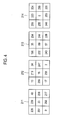
- FIG. 3 is a flowchart showing a procedure of forming a mapping table associating information on the standard views of a target object with the first feature vectors calculated from the typical plane images corresponding to the standard views.
- initial vectors may be established from the plurality of plane images corresponding to the respective standard views of the target object at S310.
- the initial vectors may be established by transforming pixel values of each plane image into a 1-dimensional matrix (i.e., 1 N), wherein N is the number of the pixels. For example, assuming that four plane images 211-214 corresponding to the parasternal view, apical view, subcostal view and suprasternal view are provided, as shown in FIG.
- a mean vector of the initial vectors x 1 -x 4 may be calculated at S320, and then the mean vector may be stored in the storage unit 110.
- An intermediate matrix x ⁇ may be obtained by using the intermediate vectors x 1 - x 4 at S340.
- a covariance matrix ⁇ may be calculated from the intermediate matrix x at S350.
- eigenvalues may be calculated from the covariance matrix ⁇ , and then eigenvectors corresponding to the respective eigenvalues may be calculated.
- the eigenvalues and the eigenvectors may be calculated by using Jacobi algorithm.
- the eigenvectors may be structured to a matrix, which may represent an eigenspace, at S380.
- the first feature vectors of the respective plane images corresponding to the respective standard views may be calculated by using the intermediate vectors calculated at S330 and the eigenspace formed at S360.
- FIG. 5 is a block diagram showing an illustrative embodiment of the processing unit 140.
- the processing unit 140 may include an initial vector establishing section 141.
- the initial vector establishing section 141 may be operable to establish an initial vector based on the pixel values of the ultrasound image provided from the ultrasound image forming unit 130.
- the initial vector establishing section 141 may be operable to establish the initial vector by transforming pixel values of the ultrasound image into a 1-dimensional matrix (i.e., 1 N), wherein N is the number of the pixels.
- the processing unit 140 may further include an intermediate vector calculating section 142.
- the intermediate vector forming section 142 may be operable to subtract a mean vector from the initial vector to thereby obtain an intermediate vector.
- the stored mean vector in the storage unit 110 may be used as the mean vector.
- the processing unit 140 may further include a covariance matrix calculating section 143.
- the covariance matrix calculating section 143 may be operable to calculate a covariance matrix from the intermediate matrix.
- the calculation of the covariance matrix may be performed in the same manner with the operation of S350 in FIG. 3 .
- the detailed description of calculating the covariance matrix may be omitted herein.
- the processing unit 140 may further include an eigenspace forming section 144.
- the eigenspace forming section 144 may be operable to calculate eigenvalues and eigenvectors from the covariance matrix calculated in the covariance matrix calculating section 143.
- the eigenvalues and the eigenvectors may be calculated by using Jacobi algorithm.
- the eigenspace forming section 144 may be further operable to form an eigenspace by using the eigenvalues and eigenvectors.
- the eigenspace forming section 144 may be operable to form the eigenspace similar to the operation of S360 in FIG. 3 .
- the processing unit 140 may further include a feature vector calculating section 145.
- the feature vector calculating section 145 may be operable to calculate a second feature vector by using the intermediate vector calculated in the intermediate vector forming section 142 and the eigenspace formed in the Eigen space forming section 144.
- the processing unit 140 may further include a standard view detecting section 146.
- the standard view detecting section 146 may be operable to retrieve the mapping table to detect a standard view corresponding to the second feature vector calculated in the feature vector calculating section 145.
- the standard view detecting section 146 may be operable to compute an Euclidean distance between the second feature vector and each of the first feature vectors of the mapping table stored in the storage unit 110 to detect the corresponding standard view. That is, the standard view detecting section 146 may be operable to select one of the first feature vectors, which has the closest Euclidean distance, and access the storage unit 100 to find one of the standard views corresponding to the selected first feature vector from the mapping table.
- the extracted information may be displayed on a screen of the display unit 150.
- the ultrasound image forming unit 130 and the processing unit 140 are described in different elements in one embodiment, the ultrasound image forming unit 130 and the processing unit 140 may be embodied in a single processor. Also, although it is described above that the feature vectors are calculated by using principle component analysis in one embodiment, the feature vectors may be calculated by other statistical algorithm, such as Hidden Markove model, support vector machine algorithm, etc.
Landscapes
- Engineering & Computer Science (AREA)
- Physics & Mathematics (AREA)
- General Physics & Mathematics (AREA)
- Theoretical Computer Science (AREA)
- Computer Vision & Pattern Recognition (AREA)
- Health & Medical Sciences (AREA)
- Radar, Positioning & Navigation (AREA)
- Remote Sensing (AREA)
- Computer Networks & Wireless Communication (AREA)
- Life Sciences & Earth Sciences (AREA)
- Multimedia (AREA)
- Artificial Intelligence (AREA)
- Evolutionary Computation (AREA)
- General Health & Medical Sciences (AREA)
- Medical Informatics (AREA)
- Computing Systems (AREA)
- Software Systems (AREA)
- Data Mining & Analysis (AREA)
- Databases & Information Systems (AREA)
- Radiology & Medical Imaging (AREA)
- Heart & Thoracic Surgery (AREA)
- Evolutionary Biology (AREA)
- General Engineering & Computer Science (AREA)
- Biophysics (AREA)
- Nuclear Medicine, Radiotherapy & Molecular Imaging (AREA)
- Pathology (AREA)
- Bioinformatics & Cheminformatics (AREA)
- Biomedical Technology (AREA)
- Bioinformatics & Computational Biology (AREA)
- Molecular Biology (AREA)
- Surgery (AREA)
- Animal Behavior & Ethology (AREA)
- Public Health (AREA)
- Veterinary Medicine (AREA)
- Ultra Sonic Daignosis Equipment (AREA)
- Image Processing (AREA)
- Image Analysis (AREA)
Applications Claiming Priority (1)
| Application Number | Priority Date | Filing Date | Title |
|---|---|---|---|
| KR1020080115316A KR101051567B1 (ko) | 2008-11-19 | 2008-11-19 | 표준 단면 정보를 제공하는 초음파 시스템 및 방법 |
Publications (2)
| Publication Number | Publication Date |
|---|---|
| EP2189807A2 true EP2189807A2 (fr) | 2010-05-26 |
| EP2189807A3 EP2189807A3 (fr) | 2010-12-08 |
Family
ID=42008490
Family Applications (1)
| Application Number | Title | Priority Date | Filing Date |
|---|---|---|---|
| EP09174271A Withdrawn EP2189807A3 (fr) | 2008-11-19 | 2009-10-28 | Recherche d'une vue standard correspondant à une image ultrasonore acquise |
Country Status (4)
| Country | Link |
|---|---|
| US (1) | US20100125203A1 (fr) |
| EP (1) | EP2189807A3 (fr) |
| JP (1) | JP2010119847A (fr) |
| KR (1) | KR101051567B1 (fr) |
Families Citing this family (7)
| Publication number | Priority date | Publication date | Assignee | Title |
|---|---|---|---|---|
| KR101446780B1 (ko) * | 2012-06-01 | 2014-10-01 | 삼성메디슨 주식회사 | 초음파 영상과 초음파 영상에 관련된 정보를 디스플레이하기 위한 방법 및 장치 |
| KR102255831B1 (ko) | 2014-03-26 | 2021-05-25 | 삼성전자주식회사 | 초음파 장치 및 초음파 장치의 영상 인식 방법 |
| JP6498316B2 (ja) * | 2015-12-02 | 2019-04-10 | 株式会社日立製作所 | 超音波撮像装置、および画像処理方法 |
| CN112184656B (zh) * | 2020-09-24 | 2024-04-16 | 广州爱孕记信息科技有限公司 | 基于超声动态图像的胎儿切面的确定方法及装置 |
| KR102917172B1 (ko) * | 2022-04-19 | 2026-01-23 | 주식회사 온택트헬스 | 심장 초음파에 대한 가이드 방법 및 이를 이용한 심장 초음파에 대한 가이드용 디바이스 |
| KR102819588B1 (ko) * | 2022-08-01 | 2025-06-13 | 주식회사 온택트헬스 | 도플러 초음파 영상에 대한 정보 제공 방법 및 이를 이용한 도플러 초음파 영상에 대한 정보 제공용 디바이스 |
| KR102771062B1 (ko) * | 2022-08-02 | 2025-02-19 | 연세대학교 산학협력단 | 대상체에 대한 표준 평면 정보 제공 방법 및 이를 수행하는 디바이스 |
Family Cites Families (6)
| Publication number | Priority date | Publication date | Assignee | Title |
|---|---|---|---|---|
| AU2317900A (en) * | 1999-02-05 | 2000-08-25 | Yoav Smith | Similarity measurement method for the classification of medical images into predetermined categories |
| KR100392094B1 (ko) * | 2001-09-11 | 2003-07-22 | 주식회사 메디슨 | 초음파 영상 최적화 시스템 |
| US7672491B2 (en) * | 2004-03-23 | 2010-03-02 | Siemens Medical Solutions Usa, Inc. | Systems and methods providing automated decision support and medical imaging |
| JP4455548B2 (ja) * | 2005-07-26 | 2010-04-21 | キヤノン株式会社 | 像加熱装置 |
| US20080009722A1 (en) * | 2006-05-11 | 2008-01-10 | Constantine Simopoulos | Multi-planar reconstruction for ultrasound volume data |
| CN101522107B (zh) * | 2006-10-10 | 2014-02-05 | 株式会社日立医药 | 医用图像诊断装置、医用图像测量方法、医用图像测量程序 |
-
2008
- 2008-11-19 KR KR1020080115316A patent/KR101051567B1/ko active Active
-
2009
- 2009-10-28 EP EP09174271A patent/EP2189807A3/fr not_active Withdrawn
- 2009-11-17 JP JP2009262229A patent/JP2010119847A/ja active Pending
- 2009-11-18 US US12/621,353 patent/US20100125203A1/en not_active Abandoned
Also Published As
| Publication number | Publication date |
|---|---|
| KR101051567B1 (ko) | 2011-07-22 |
| JP2010119847A (ja) | 2010-06-03 |
| KR20100056240A (ko) | 2010-05-27 |
| US20100125203A1 (en) | 2010-05-20 |
| EP2189807A3 (fr) | 2010-12-08 |
Similar Documents
| Publication | Publication Date | Title |
|---|---|---|
| US11100665B2 (en) | Anatomical measurements from ultrasound data | |
| US10856849B2 (en) | Ultrasound diagnostic device and ultrasound diagnostic device control method | |
| US8317708B2 (en) | Setting an optimal image parameter in an ultrasound system | |
| US8343054B1 (en) | Methods and apparatus for ultrasound imaging | |
| US20190369220A1 (en) | Methods and systems for filtering ultrasound image clutter | |
| EP2189807A2 (fr) | Recherche d'une vue standard correspondant à une image ultrasonore acquise | |
| US8083680B2 (en) | Ultrasound system and method for forming an ultrasound image | |
| US20080044054A1 (en) | Ultrasound system and method for forming an ultrasound image | |
| US8900147B2 (en) | Performing image process and size measurement upon a three-dimensional ultrasound image in an ultrasound system | |
| US20090227869A1 (en) | Volume Measurement In An Ultrasound System | |
| US20110137168A1 (en) | Providing a three-dimensional ultrasound image based on a sub region of interest in an ultrasound system | |
| US9151841B2 (en) | Providing an ultrasound spatial compound image based on center lines of ultrasound images in an ultrasound system | |
| US20110087095A1 (en) | Ultrasound system generating an image based on brightness value of data | |
| US8696576B2 (en) | Ultrasound system and method for providing change trend image | |
| US9216007B2 (en) | Setting a sagittal view in an ultrasound system | |
| KR102321853B1 (ko) | 교차 평면 초음파 이미지로 움직이는 구조의 시각화를 향상시키는 방법 및 시스템 | |
| US20110028842A1 (en) | Providing A Plurality Of Slice Images In An Ultrasound System | |
| EP3813673B1 (fr) | Procédés et systèmes permettant d'effectuer une quantification de pression transvalvulaire | |
| EP3274959B1 (fr) | Segmentation optimale d'organes par ultrasons | |
| EP0934724A1 (fr) | Appareil diagnostique à ultrasons | |
| US12471879B2 (en) | Methods and systems for obtaining a 3D vector flow field | |
| US20120083694A1 (en) | Stretching based strain imaging in an ultrasound system |
Legal Events
| Date | Code | Title | Description |
|---|---|---|---|
| PUAI | Public reference made under article 153(3) epc to a published international application that has entered the european phase |
Free format text: ORIGINAL CODE: 0009012 |
|
| AK | Designated contracting states |
Kind code of ref document: A2 Designated state(s): AT BE BG CH CY CZ DE DK EE ES FI FR GB GR HR HU IE IS IT LI LT LU LV MC MK MT NL NO PL PT RO SE SI SK SM TR |
|
| AX | Request for extension of the european patent |
Extension state: AL BA RS |
|
| PUAL | Search report despatched |
Free format text: ORIGINAL CODE: 0009013 |
|
| AK | Designated contracting states |
Kind code of ref document: A3 Designated state(s): AT BE BG CH CY CZ DE DK EE ES FI FR GB GR HR HU IE IS IT LI LT LU LV MC MK MT NL NO PL PT RO SE SI SK SM TR |
|
| AX | Request for extension of the european patent |
Extension state: AL BA RS |
|
| RIC1 | Information provided on ipc code assigned before grant |
Ipc: G06K 9/62 20060101ALI20101103BHEP Ipc: G01S 7/52 20060101AFI20100322BHEP |
|
| STAA | Information on the status of an ep patent application or granted ep patent |
Free format text: STATUS: THE APPLICATION IS DEEMED TO BE WITHDRAWN |
|
| 18D | Application deemed to be withdrawn |
Effective date: 20110609 |