EP2189877A2 - Elektronisches Gerät zur Verringerung des Energieverbrauchs bei der Abschaltung einer Computerhauptplatine - Google Patents
Elektronisches Gerät zur Verringerung des Energieverbrauchs bei der Abschaltung einer Computerhauptplatine Download PDFInfo
- Publication number
- EP2189877A2 EP2189877A2 EP09162791A EP09162791A EP2189877A2 EP 2189877 A2 EP2189877 A2 EP 2189877A2 EP 09162791 A EP09162791 A EP 09162791A EP 09162791 A EP09162791 A EP 09162791A EP 2189877 A2 EP2189877 A2 EP 2189877A2
- Authority
- EP
- European Patent Office
- Prior art keywords
- power
- computer motherboard
- electronic device
- switching signal
- stand
- Prior art date
- Legal status (The legal status is an assumption and is not a legal conclusion. Google has not performed a legal analysis and makes no representation as to the accuracy of the status listed.)
- Granted
Links
Images

Classifications
-
- G—PHYSICS
- G06—COMPUTING OR CALCULATING; COUNTING
- G06F—ELECTRIC DIGITAL DATA PROCESSING
- G06F1/00—Details not covered by groups G06F3/00 - G06F13/00 and G06F21/00
- G06F1/26—Power supply means, e.g. regulation thereof
- G06F1/32—Means for saving power
- G06F1/3203—Power management, i.e. event-based initiation of a power-saving mode
- G06F1/3234—Power saving characterised by the action undertaken
- G06F1/3287—Power saving characterised by the action undertaken by switching off individual functional units in the computer system
-
- Y—GENERAL TAGGING OF NEW TECHNOLOGICAL DEVELOPMENTS; GENERAL TAGGING OF CROSS-SECTIONAL TECHNOLOGIES SPANNING OVER SEVERAL SECTIONS OF THE IPC; TECHNICAL SUBJECTS COVERED BY FORMER USPC CROSS-REFERENCE ART COLLECTIONS [XRACs] AND DIGESTS
- Y02—TECHNOLOGIES OR APPLICATIONS FOR MITIGATION OR ADAPTATION AGAINST CLIMATE CHANGE
- Y02D—CLIMATE CHANGE MITIGATION TECHNOLOGIES IN INFORMATION AND COMMUNICATION TECHNOLOGIES [ICT], I.E. INFORMATION AND COMMUNICATION TECHNOLOGIES AIMING AT THE REDUCTION OF THEIR OWN ENERGY USE
- Y02D10/00—Energy efficient computing, e.g. low power processors, power management or thermal management
Definitions
- the present invention relates to an electronic device for reducing power consumption during power off of computer motherboard, and particularly to a computer motherboard at S5 soft off state of ACPI, which will make the computer motherboard enter like G3 mechanical off state of ACPI.
- the conventional computer motherboard is conformed to the Advanced Configuration and Power Interface (ACPI) specification.
- ACPI Advanced Configuration and Power Interface
- the related prior art is to employ the individual control method on the conventional computer motherboard, which is to respectively cut off the input stand-by power portion for each power-consuming component.
- the method of the prior art can be applied to the same batch of computer motherboards with the same design, for another batch of computer motherboards with different design, it needs to make a special design suitable for them
- the prior art will cause the waste of repetitive design, and implicitly increase the manufacturing cost for computer motherboards.
- the US Patent No. 6,266,776 titled "ACPI sleep control” disclosed that when the status of the internal battery or the external power supply has changed, the change can be detected by the embedded controller. The change will employ the Power Management Event Signal (POWER_PME) and SCI interrupt, so the operating system will be notified of this change. The current system state of the operating system will be switched to another system state.
- US Patent No. 6,266,776 did not disclose that, at S5 soft off state of ACPI, the computer motherboard can be further enabled to enter like G3 mechanical off state of ACPI.
- the first object of the present invention is to provide an electronic device for reducing power consumption during power off of computer motherboards.
- the second object of the present invention is to provide a computer motherboard, which, when being at S5 soft off state of ACPI, will enter like G3 mechanical off state of ACPI.
- the present invention provides an electronic device for reducing power consumption during power off of computer motherboards, which employs a computer motherboard conformed to the Advanced Configuration and Power Interface (ACPI) specification.
- the electronic device comprises: a first device configured to control the stand-by power of a power supply to form a closed or opened connection with the computer motherboard; a second device configured to receive a power switching signal generated by a power switch, and, after receiving the power switching signal, to make the first device control the stand-by power to form an electrical connection with the computer motherboard, and to copy the power switching signal and output the copied power switching signal to the computer motherboard, and to determine that when the computer motherboard is at S4 state or S5 state of ACPI, make the first device control the stand-by power to form an electrical disconnection with the computer motherboard; wherein, the first device and the second device are electrically connected to the stand-by power.
- ACPI Advanced Configuration and Power Interface
- the present invention provides a computer motherboard, in which the computer motherboard is conformed to the Advanced Configuration and Power Interface (ACPI) specification, which comprises: a first device configured to control the stand-by power of a power supply to form an electrical connection or disconnection with the computer motherboard; a second device configured to receive a power switching signal generated by a power switch, and, after receiving the power switching signal, to make the first device control the stand-by power to form an electrical connection with the computer motherboard, and to copy the power switching signal and output the copied power switching signal to the computer motherboard, and to determine that when the computer motherboard is at S4 state or S5 state of ACPI, make the first device control the stand-by power to form an electrical disconnection with the computer motherboard; wherein, the first device and the second device are electrically connected to the stand-by power.
- ACPI Advanced Configuration and Power Interface
- FIG. 1 is a structural diagram for an electronic device for reduction power consumption during power off of computer motherboards according to the present invention.
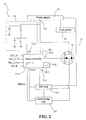
- FIG. 2 is an embodiment of the present invention according to FIG. 1 .
- the electronic device 10 for reducing power consumption during power off of computer motherboard according to the present invention has the major function of isolating the stand-by power 30a, such as 5V (or one of 3V, 12V, 19V, and etc.) stand-by power, of the power supply 30, such as ATX power supply, from entering the computer motherboard 20.
- the stand-by power 30a such as 5V (or one of 3V, 12V, 19V, and etc.) stand-by power, of the power supply 30, such as ATX power supply, from entering the computer motherboard 20.
- the electronic device 10 After soft off of the computer motherboard 20, the electronic device 10 will cut off a portion of electric components consuming the stand-by power 30a on the computer motherboard 20, and only supply the stand-by power to the electronic device 10 itself. When the user pressed the power button, the electronic device 10 will connect the stand-by power 30a to the computer motherboard 20.
- the electronic device 10 can be applied to the computer motherboard conformed to the Advanced Configuration and Power Interface (ACPI) specification.
- ACPI Advanced Configuration and Power Interface
- the computer motherboard 20 equipped with the electronic device 10 is at S5 soft off state of ACPI, the electronic device 10 will make the computer motherboard 20 enter like G3 mechanical off state of ACPI. At this time, only the electronic device 10 and the electric components related to the power button will consume the stand-by power, while all the other electric components of the computer motherboard 20 consume no stand-by power at all.
- the other power supply from the power supply 30, such as +12V, -12V, +5V, 3.3V, and etc, will be directly connected to the core power 201 on the computer motherboard 20.
- the computer motherboard 20 equipped with the electronic device 10 will surely reduce the power consumption as much as possible to the minimum than the conventional computer motherboard will do.
- the electronic device 10 can reduce the power consumption of the computer motherboard 20 after power off waiting for power on.
- the electronic device 10 comprises a first device 101 and a second device 103, which are respectively described as follows.
- the main function of the first device 101 is used to control the stand-by power 30a of the power supply 30 forming an electrical connection or disconnection with the computer motherboard 20.
- the specific component of the first device 101 can employ the MOSFET (Metal-oxide semiconductor field effective transistor). With the control on the gate of MOSFET 101 through the second device 103, it can achieve the control of forming an electrical connection or disconnection between the stand-by power 30a of the power supply 30 and the computer motherboard 20.
- MOSFET Metal-oxide semiconductor field effective transistor
- the functions of the second device 103 are described respectively as follows.
- the main elements for specifically implementing the second device 103 comprise at least a micro-controller 1031.
- the first function of the second device 103 is used to receive the power switching signal 105a generated by the power button 105, and, after receiving the power switching signal 105a, to make the first device 101 control the stand-by power 30a and the computer motherboard 20 to form an electrical connection. Except the electronic device 10 and the electric components related to the power button 105, the computer motherboard 20 is a completely electrical disconnection with the stand-by power 30a under the power off state.
- the micro-controller 1031 when the micro-controller 1031 received the power switching signal 105a, the micro-controller 1031 will output a connection control signal 103a to the gate of the MOSFET 101, so as to conduct the MOSFET 101, and form an electrical connection between the stand-by power 30a and the computer motherboard 20. From this moment on, all of the electric components of the computer motherboard 20 can be supplied by the stand-by power 30a.
- the present invention can add a soft start circuit unit 1033 for preventing the MOSFET 101 from burning out.
- the soft start circuit unit 1033 can be implemented using the related conventional circuit means.
- the present invention can add a charge pump circuit unit 1035.
- the charge pump circuit unit 1035 can be implemented using the related circuit means.
- the second function of the second device 103 is used to copy the power switching signal 105a, and output the copied power switching signal 105a' to the computer motherboard 20.
- the computer motherboard 20 supplied with the stand-by power 30a will generate a RSMRST signal (RSMRST signal can be generated by, for example, the second device 103 or SIO chip 203), and transmit it to the Southbridge chip 205.
- the second device 103 will wait for a predetermined period of time. The length of the predetermined period of time depends on the waiting time required by the computer motherboard 20 to complete generating the RSMRST signal, for example, the predetermined time can be 100 ms.
- the micro-controller 1031 after the MOSFET 101 being conducted, will immediately wait for the predetermined time of 100ms.
- the micro-controller 1031 After 100ms elapses, the micro-controller 1031 will immediately generate a power switching signal 105a', and transmit the power switching signal 105a' to the SIO chip 203. After the SIO chip 203 receives the power switching signal 105a', the power on operation of the computer motherboard 205 is exactly the same as that of the conventional computer motherboard.
- the third function of the second device 103 is used to determine when the computer motherboard 20 is at the sleep mode S4 state or S5 state of ACPI, make the first device 101 control the stand-by power 103a to form an electrical disconnection with the computer motherboard 20.
- the computer motherboard 20 After the user of the computer motherboard 20 issued the power off command for power off in the window operating system, the computer motherboard 20 will enter the sleep mode S4 state or S5 state of ACPI shortly.
- the micro-controller 1031 will receive the S4 or S5 signal state, and cut off the MOSFET 101, so the stand-by power 30a will form an electrical disconnection with the computer motherboard 20.
- the second device 103 can also employ the Application Specific Integrated Circuit (ASIC) as an embodiment.
- ASIC Application Specific Integrated Circuit
- the truth table for ASIC 103 is show below: ACPI state Signal 105a wake signal S3 signal S4 signal SLP_M signal Stand-b y power 30a' Signal 103a Signal 105a' G3->S0 0 0->1 0->1 0->1 0->1 0->1 Output after waiting 100ms.
- the electronic device 10 can not only process the power switching signal 105a from the power button 105, but also further process the sleep mode S4 and S5 signal of ACPI, and the Wake_Event signal.
- the abovementioned sleep mode S4 and S5 signal, the Wake_Event signal, and the SLP_M signal are all from the Southbridge chip 205, wherein the SLP_M signal is a control signal related to the Active Management Technology (AMT) from IntelTM on a motherboard, and the function of SLP_M signal is to be used by a remote wake-up system of network management.
- AMT Active Management Technology
- the SIO chip 203 and Southbridge chip 205 can both directly employ the conventional SIO chip and the conventional Southbridge chip.
- the electronic device 10 according to the present invention can be configured on the computer motherboard 20, or the electronic device 10 according to the present invention can be integrated into the SIO chip 203 on the computer motherboard 20.
- the embedded memory 1031a of the micro-controller 1031 can be used as firmware.
- the embedded memory 1031a can be used to store and execute the program codes of the above-mentioned first, second and third functions.
- the microcontroller 1031 can be connected to the Southbridge chip 205 through the SM bus, so that the update for new firmware of the micro-controller 1031 can be completed through the SM bus.
- the prevent invention provides an electronic device for reducing power consumption during power off of computer motherboards, so that when the computer motherboard is at S5 soft off state of ACPI, it will make the computer motherboard enter like G3 mechanical off state of ACPI for automatically achieving the power saving. This feature is the advantage and the maximum feature of the present invention.
Landscapes
- Engineering & Computer Science (AREA)
- Theoretical Computer Science (AREA)
- General Engineering & Computer Science (AREA)
- Physics & Mathematics (AREA)
- General Physics & Mathematics (AREA)
- Computer Hardware Design (AREA)
- Computing Systems (AREA)
- Power Sources (AREA)
Applications Claiming Priority (1)
| Application Number | Priority Date | Filing Date | Title |
|---|---|---|---|
| TW097144790A TW201020749A (en) | 2008-11-20 | 2008-11-20 | Electronic device for reducing shutdown power consumption of computer motherboard |
Publications (3)
| Publication Number | Publication Date |
|---|---|
| EP2189877A2 true EP2189877A2 (de) | 2010-05-26 |
| EP2189877A3 EP2189877A3 (de) | 2012-07-25 |
| EP2189877B1 EP2189877B1 (de) | 2018-12-12 |
Family
ID=40758862
Family Applications (1)
| Application Number | Title | Priority Date | Filing Date |
|---|---|---|---|
| EP09162791.9A Active EP2189877B1 (de) | 2008-11-20 | 2009-06-16 | Elektronisches Gerät zur Verringerung des Energieverbrauchs bei der Abschaltung einer Computerhauptplatine |
Country Status (5)
| Country | Link |
|---|---|
| US (1) | US8195966B2 (de) |
| EP (1) | EP2189877B1 (de) |
| JP (1) | JP3150567U (de) |
| DE (1) | DE202009003607U1 (de) |
| TW (1) | TW201020749A (de) |
Families Citing this family (12)
| Publication number | Priority date | Publication date | Assignee | Title |
|---|---|---|---|---|
| CN101872232A (zh) * | 2009-04-27 | 2010-10-27 | 联想(北京)有限公司 | 一种控制装置、主板、计算机 |
| TWI582575B (zh) | 2011-03-17 | 2017-05-11 | 和碩聯合科技股份有限公司 | 電子裝置 |
| US9727124B2 (en) * | 2011-04-19 | 2017-08-08 | Apple Inc. | Power saving application update in a portable electronic device |
| CN102937829A (zh) * | 2011-08-15 | 2013-02-20 | 鸿富锦精密工业(深圳)有限公司 | 节能管理电路 |
| CN103064488A (zh) * | 2011-10-21 | 2013-04-24 | 鸿富锦精密工业(深圳)有限公司 | 电源控制电路 |
| US9021288B2 (en) * | 2012-05-31 | 2015-04-28 | Apple Inc. | Method and apparatus for recovery from low power state |
| CN103699175A (zh) * | 2012-09-28 | 2014-04-02 | 鸿富锦精密工业(武汉)有限公司 | 主板 |
| TWI547796B (zh) * | 2014-11-13 | 2016-09-01 | 鴻海精密工業股份有限公司 | 主機板供電電路 |
| CN105204403A (zh) * | 2015-09-28 | 2015-12-30 | 珠海格力电器股份有限公司 | 时钟电路、基于时钟电路的供电控制方法和空调 |
| TWI693513B (zh) * | 2018-09-26 | 2020-05-11 | 神雲科技股份有限公司 | 伺服器系統及其省電方法 |
| CN111142646B (zh) * | 2018-11-02 | 2023-11-07 | 佛山市顺德区顺达电脑厂有限公司 | 服务器系统及其省电方法 |
| CN111124088B (zh) * | 2019-12-25 | 2021-12-24 | 联想(北京)有限公司 | 一种控制方法及电子设备 |
Citations (1)
| Publication number | Priority date | Publication date | Assignee | Title |
|---|---|---|---|---|
| US6266776B1 (en) | 1997-11-28 | 2001-07-24 | Kabushiki Kaisha Toshiba | ACPI sleep control |
Family Cites Families (14)
| Publication number | Priority date | Publication date | Assignee | Title |
|---|---|---|---|---|
| US6678831B1 (en) * | 1997-12-11 | 2004-01-13 | Hewlett-Packard Development Company, L.P. | Managing power states in a computer system |
| KR100626359B1 (ko) * | 1999-09-10 | 2006-09-20 | 삼성전자주식회사 | 컴퓨터 시스템의 전원 관리 방법 |
| US6499102B1 (en) * | 1999-12-29 | 2002-12-24 | Intel Corporation | Method of dynamically changing the lowest sleeping state in ACPI |
| US6691234B1 (en) * | 2000-06-16 | 2004-02-10 | Intel Corporation | Method and apparatus for executing instructions loaded into a reserved portion of system memory for transitioning a computer system from a first power state to a second power state |
| US6768222B1 (en) * | 2000-07-11 | 2004-07-27 | Advanced Micro Devices, Inc. | System and method for delaying power supply power-up |
| US7380144B2 (en) * | 2004-03-30 | 2008-05-27 | Hewlett-Packard Development Company, L.P. | Enabling and disabling of powering-off of computer system |
| US7240227B2 (en) * | 2004-08-15 | 2007-07-03 | International Business Machines Corporation | Automatic restart and resume of computing system upon reapplication of external power |
| US7296171B2 (en) * | 2004-11-10 | 2007-11-13 | Microsoft Corporation | Selecting a power state based on predefined parameters |
| US7472291B2 (en) * | 2005-04-15 | 2008-12-30 | Shuttle Inc. | Method and apparatus for integrating ACPI functionality and power button functionality into a single power key |
| US20070027981A1 (en) * | 2005-07-27 | 2007-02-01 | Giovanni Coglitore | Computer diagnostic system |
| US20080077726A1 (en) * | 2006-09-07 | 2008-03-27 | Gilbert David W | Computer remote control module, interface, system and method |
| US7849334B2 (en) * | 2006-09-29 | 2010-12-07 | Intel Coporation | Transitioning a computing platform to a low power system state |
| CN201000602Y (zh) * | 2007-01-05 | 2008-01-02 | 鸿富锦精密工业(深圳)有限公司 | 电脑关机节能电路 |
| US20100332870A1 (en) * | 2009-06-25 | 2010-12-30 | Micro-Star International Co., Ltd. | Electronic device for reducing power consumption of computer motherboard and motherboard thereof |
-
2008
- 2008-11-20 TW TW097144790A patent/TW201020749A/zh unknown
-
2009
- 2009-02-25 US US12/392,688 patent/US8195966B2/en active Active
- 2009-03-05 JP JP2009001274U patent/JP3150567U/ja not_active Expired - Lifetime
- 2009-03-13 DE DE202009003607U patent/DE202009003607U1/de not_active Expired - Lifetime
- 2009-06-16 EP EP09162791.9A patent/EP2189877B1/de active Active
Patent Citations (1)
| Publication number | Priority date | Publication date | Assignee | Title |
|---|---|---|---|---|
| US6266776B1 (en) | 1997-11-28 | 2001-07-24 | Kabushiki Kaisha Toshiba | ACPI sleep control |
Also Published As
| Publication number | Publication date |
|---|---|
| US8195966B2 (en) | 2012-06-05 |
| TW201020749A (en) | 2010-06-01 |
| EP2189877A3 (de) | 2012-07-25 |
| DE202009003607U1 (de) | 2009-06-10 |
| US20100125743A1 (en) | 2010-05-20 |
| JP3150567U (ja) | 2009-05-21 |
| EP2189877B1 (de) | 2018-12-12 |
Similar Documents
| Publication | Publication Date | Title |
|---|---|---|
| EP2189877A2 (de) | Elektronisches Gerät zur Verringerung des Energieverbrauchs bei der Abschaltung einer Computerhauptplatine | |
| EP2267575B1 (de) | Elektronische Vorrichtung zur Verringerung des Energieverbrauchs einer Computerhauptplatine und Hauptplatine damit | |
| EP2239647B1 (de) | Hauptplatine mit Elektronische Vorrichtung zur Verringerung des Energieverbrauchs bei Schlafstrombetrieb einer Computerhauptplatine | |
| CN100478843C (zh) | 减少计算机系统于工作状态下电源消耗的方法及芯片组 | |
| KR101519082B1 (ko) | 슬리프 프로세서 | |
| US7853815B2 (en) | Method and apparatus for controlling power supply in a computer system under low power consumption mode | |
| CN104062914B (zh) | 电子装置 | |
| CN101170777A (zh) | 一种实现多模移动终端睡眠/唤醒的方法 | |
| CN101907918B (zh) | 节省待机/关机状态功率消耗的计算机系统及其相关方法 | |
| US20130132746A1 (en) | Bridging device and power saving method thereof | |
| TW515995B (en) | Method allowing to configure computer system as wake on LAN | |
| CN101403943A (zh) | 智能化计算机电源一体化系统 | |
| CN101727163A (zh) | 具有省电功能的嵌入式系统及其相关省电方法 | |
| WO2021078261A1 (zh) | 一种供电控制方法、系统及设备 | |
| US7884885B2 (en) | Power control method used with TV module of portable electronic apparatus | |
| CN201298200Y (zh) | 智能化计算机电源一体化系统 | |
| WO2024109333A1 (zh) | Wifi模组的通信方法、wifi模组和终端设备 | |
| CN219718089U (zh) | 上电和/或下电控制装置及电子设备 | |
| CN101751110B (zh) | 用于减少计算机主机板关机耗电的电子装置及计算机主板 | |
| CN106325461B (zh) | 一种信息处理方法及电子设备 | |
| CN217010957U (zh) | 上下电控制电路及摄像设备 | |
| US20250117177A1 (en) | Control method and device and first electronic device | |
| CN109407577B (zh) | 一种唤醒电路、唤醒方法以及电饭煲 | |
| CN100365542C (zh) | 转换不省电处理器电子装置为省电的节电方法及节电电路 | |
| CN101788843A (zh) | 反应电源关断的电路装置及其方法 |
Legal Events
| Date | Code | Title | Description |
|---|---|---|---|
| PUAI | Public reference made under article 153(3) epc to a published international application that has entered the european phase |
Free format text: ORIGINAL CODE: 0009012 |
|
| AK | Designated contracting states |
Kind code of ref document: A2 Designated state(s): AT BE BG CH CY CZ DE DK EE ES FI FR GB GR HR HU IE IS IT LI LT LU LV MC MK MT NL NO PL PT RO SE SI SK TR |
|
| AX | Request for extension of the european patent |
Extension state: AL BA RS |
|
| PUAL | Search report despatched |
Free format text: ORIGINAL CODE: 0009013 |
|
| AK | Designated contracting states |
Kind code of ref document: A3 Designated state(s): AT BE BG CH CY CZ DE DK EE ES FI FR GB GR HR HU IE IS IT LI LT LU LV MC MK MT NL NO PL PT RO SE SI SK TR |
|
| AX | Request for extension of the european patent |
Extension state: AL BA RS |
|
| RIC1 | Information provided on ipc code assigned before grant |
Ipc: G06F 1/32 20060101AFI20120619BHEP |
|
| 17P | Request for examination filed |
Effective date: 20130122 |
|
| 17Q | First examination report despatched |
Effective date: 20130820 |
|
| STAA | Information on the status of an ep patent application or granted ep patent |
Free format text: STATUS: EXAMINATION IS IN PROGRESS |
|
| GRAP | Despatch of communication of intention to grant a patent |
Free format text: ORIGINAL CODE: EPIDOSNIGR1 |
|
| STAA | Information on the status of an ep patent application or granted ep patent |
Free format text: STATUS: GRANT OF PATENT IS INTENDED |
|
| INTG | Intention to grant announced |
Effective date: 20180420 |
|
| GRAS | Grant fee paid |
Free format text: ORIGINAL CODE: EPIDOSNIGR3 |
|
| GRAA | (expected) grant |
Free format text: ORIGINAL CODE: 0009210 |
|
| STAA | Information on the status of an ep patent application or granted ep patent |
Free format text: STATUS: THE PATENT HAS BEEN GRANTED |
|
| AK | Designated contracting states |
Kind code of ref document: B1 Designated state(s): AT BE BG CH CY CZ DE DK EE ES FI FR GB GR HR HU IE IS IT LI LT LU LV MC MK MT NL NO PL PT RO SE SI SK TR |
|
| REG | Reference to a national code |
Ref country code: GB Ref legal event code: FG4D |
|
| REG | Reference to a national code |
Ref country code: CH Ref legal event code: EP |
|
| REG | Reference to a national code |
Ref country code: AT Ref legal event code: REF Ref document number: 1076848 Country of ref document: AT Kind code of ref document: T Effective date: 20181215 |
|
| REG | Reference to a national code |
Ref country code: DE Ref legal event code: R096 Ref document number: 602009056141 Country of ref document: DE |
|
| REG | Reference to a national code |
Ref country code: IE Ref legal event code: FG4D |
|
| REG | Reference to a national code |
Ref country code: NL Ref legal event code: MP Effective date: 20181212 |
|
| REG | Reference to a national code |
Ref country code: LT Ref legal event code: MG4D |
|
| PG25 | Lapsed in a contracting state [announced via postgrant information from national office to epo] |
Ref country code: BG Free format text: LAPSE BECAUSE OF FAILURE TO SUBMIT A TRANSLATION OF THE DESCRIPTION OR TO PAY THE FEE WITHIN THE PRESCRIBED TIME-LIMIT Effective date: 20190312 Ref country code: FI Free format text: LAPSE BECAUSE OF FAILURE TO SUBMIT A TRANSLATION OF THE DESCRIPTION OR TO PAY THE FEE WITHIN THE PRESCRIBED TIME-LIMIT Effective date: 20181212 Ref country code: LT Free format text: LAPSE BECAUSE OF FAILURE TO SUBMIT A TRANSLATION OF THE DESCRIPTION OR TO PAY THE FEE WITHIN THE PRESCRIBED TIME-LIMIT Effective date: 20181212 Ref country code: NO Free format text: LAPSE BECAUSE OF FAILURE TO SUBMIT A TRANSLATION OF THE DESCRIPTION OR TO PAY THE FEE WITHIN THE PRESCRIBED TIME-LIMIT Effective date: 20190312 Ref country code: LV Free format text: LAPSE BECAUSE OF FAILURE TO SUBMIT A TRANSLATION OF THE DESCRIPTION OR TO PAY THE FEE WITHIN THE PRESCRIBED TIME-LIMIT Effective date: 20181212 Ref country code: ES Free format text: LAPSE BECAUSE OF FAILURE TO SUBMIT A TRANSLATION OF THE DESCRIPTION OR TO PAY THE FEE WITHIN THE PRESCRIBED TIME-LIMIT Effective date: 20181212 Ref country code: HR Free format text: LAPSE BECAUSE OF FAILURE TO SUBMIT A TRANSLATION OF THE DESCRIPTION OR TO PAY THE FEE WITHIN THE PRESCRIBED TIME-LIMIT Effective date: 20181212 |
|
| REG | Reference to a national code |
Ref country code: AT Ref legal event code: MK05 Ref document number: 1076848 Country of ref document: AT Kind code of ref document: T Effective date: 20181212 |
|
| PG25 | Lapsed in a contracting state [announced via postgrant information from national office to epo] |
Ref country code: SE Free format text: LAPSE BECAUSE OF FAILURE TO SUBMIT A TRANSLATION OF THE DESCRIPTION OR TO PAY THE FEE WITHIN THE PRESCRIBED TIME-LIMIT Effective date: 20181212 |
|
| PG25 | Lapsed in a contracting state [announced via postgrant information from national office to epo] |
Ref country code: NL Free format text: LAPSE BECAUSE OF FAILURE TO SUBMIT A TRANSLATION OF THE DESCRIPTION OR TO PAY THE FEE WITHIN THE PRESCRIBED TIME-LIMIT Effective date: 20181212 |
|
| PG25 | Lapsed in a contracting state [announced via postgrant information from national office to epo] |
Ref country code: IT Free format text: LAPSE BECAUSE OF FAILURE TO SUBMIT A TRANSLATION OF THE DESCRIPTION OR TO PAY THE FEE WITHIN THE PRESCRIBED TIME-LIMIT Effective date: 20181212 Ref country code: CZ Free format text: LAPSE BECAUSE OF FAILURE TO SUBMIT A TRANSLATION OF THE DESCRIPTION OR TO PAY THE FEE WITHIN THE PRESCRIBED TIME-LIMIT Effective date: 20181212 Ref country code: PL Free format text: LAPSE BECAUSE OF FAILURE TO SUBMIT A TRANSLATION OF THE DESCRIPTION OR TO PAY THE FEE WITHIN THE PRESCRIBED TIME-LIMIT Effective date: 20181212 Ref country code: PT Free format text: LAPSE BECAUSE OF FAILURE TO SUBMIT A TRANSLATION OF THE DESCRIPTION OR TO PAY THE FEE WITHIN THE PRESCRIBED TIME-LIMIT Effective date: 20190412 |
|
| PG25 | Lapsed in a contracting state [announced via postgrant information from national office to epo] |
Ref country code: EE Free format text: LAPSE BECAUSE OF FAILURE TO SUBMIT A TRANSLATION OF THE DESCRIPTION OR TO PAY THE FEE WITHIN THE PRESCRIBED TIME-LIMIT Effective date: 20181212 Ref country code: IS Free format text: LAPSE BECAUSE OF FAILURE TO SUBMIT A TRANSLATION OF THE DESCRIPTION OR TO PAY THE FEE WITHIN THE PRESCRIBED TIME-LIMIT Effective date: 20190412 Ref country code: RO Free format text: LAPSE BECAUSE OF FAILURE TO SUBMIT A TRANSLATION OF THE DESCRIPTION OR TO PAY THE FEE WITHIN THE PRESCRIBED TIME-LIMIT Effective date: 20181212 Ref country code: SK Free format text: LAPSE BECAUSE OF FAILURE TO SUBMIT A TRANSLATION OF THE DESCRIPTION OR TO PAY THE FEE WITHIN THE PRESCRIBED TIME-LIMIT Effective date: 20181212 |
|
| REG | Reference to a national code |
Ref country code: DE Ref legal event code: R097 Ref document number: 602009056141 Country of ref document: DE |
|
| PLBE | No opposition filed within time limit |
Free format text: ORIGINAL CODE: 0009261 |
|
| STAA | Information on the status of an ep patent application or granted ep patent |
Free format text: STATUS: NO OPPOSITION FILED WITHIN TIME LIMIT |
|
| PG25 | Lapsed in a contracting state [announced via postgrant information from national office to epo] |
Ref country code: AT Free format text: LAPSE BECAUSE OF FAILURE TO SUBMIT A TRANSLATION OF THE DESCRIPTION OR TO PAY THE FEE WITHIN THE PRESCRIBED TIME-LIMIT Effective date: 20181212 Ref country code: DK Free format text: LAPSE BECAUSE OF FAILURE TO SUBMIT A TRANSLATION OF THE DESCRIPTION OR TO PAY THE FEE WITHIN THE PRESCRIBED TIME-LIMIT Effective date: 20181212 Ref country code: SI Free format text: LAPSE BECAUSE OF FAILURE TO SUBMIT A TRANSLATION OF THE DESCRIPTION OR TO PAY THE FEE WITHIN THE PRESCRIBED TIME-LIMIT Effective date: 20181212 |
|
| 26N | No opposition filed |
Effective date: 20190913 |
|
| PG25 | Lapsed in a contracting state [announced via postgrant information from national office to epo] |
Ref country code: MC Free format text: LAPSE BECAUSE OF FAILURE TO SUBMIT A TRANSLATION OF THE DESCRIPTION OR TO PAY THE FEE WITHIN THE PRESCRIBED TIME-LIMIT Effective date: 20181212 |
|
| REG | Reference to a national code |
Ref country code: CH Ref legal event code: PL |
|
| REG | Reference to a national code |
Ref country code: BE Ref legal event code: MM Effective date: 20190630 |
|
| PG25 | Lapsed in a contracting state [announced via postgrant information from national office to epo] |
Ref country code: TR Free format text: LAPSE BECAUSE OF FAILURE TO SUBMIT A TRANSLATION OF THE DESCRIPTION OR TO PAY THE FEE WITHIN THE PRESCRIBED TIME-LIMIT Effective date: 20181212 |
|
| PG25 | Lapsed in a contracting state [announced via postgrant information from national office to epo] |
Ref country code: IE Free format text: LAPSE BECAUSE OF NON-PAYMENT OF DUE FEES Effective date: 20190616 |
|
| PG25 | Lapsed in a contracting state [announced via postgrant information from national office to epo] |
Ref country code: CH Free format text: LAPSE BECAUSE OF NON-PAYMENT OF DUE FEES Effective date: 20190630 Ref country code: LI Free format text: LAPSE BECAUSE OF NON-PAYMENT OF DUE FEES Effective date: 20190630 Ref country code: BE Free format text: LAPSE BECAUSE OF NON-PAYMENT OF DUE FEES Effective date: 20190630 Ref country code: LU Free format text: LAPSE BECAUSE OF NON-PAYMENT OF DUE FEES Effective date: 20190616 |
|
| PG25 | Lapsed in a contracting state [announced via postgrant information from national office to epo] |
Ref country code: CY Free format text: LAPSE BECAUSE OF FAILURE TO SUBMIT A TRANSLATION OF THE DESCRIPTION OR TO PAY THE FEE WITHIN THE PRESCRIBED TIME-LIMIT Effective date: 20181212 |
|
| PG25 | Lapsed in a contracting state [announced via postgrant information from national office to epo] |
Ref country code: GR Free format text: LAPSE BECAUSE OF FAILURE TO SUBMIT A TRANSLATION OF THE DESCRIPTION OR TO PAY THE FEE WITHIN THE PRESCRIBED TIME-LIMIT Effective date: 20181212 |
|
| PG25 | Lapsed in a contracting state [announced via postgrant information from national office to epo] |
Ref country code: HU Free format text: LAPSE BECAUSE OF FAILURE TO SUBMIT A TRANSLATION OF THE DESCRIPTION OR TO PAY THE FEE WITHIN THE PRESCRIBED TIME-LIMIT; INVALID AB INITIO Effective date: 20090616 Ref country code: MT Free format text: LAPSE BECAUSE OF FAILURE TO SUBMIT A TRANSLATION OF THE DESCRIPTION OR TO PAY THE FEE WITHIN THE PRESCRIBED TIME-LIMIT Effective date: 20181212 |
|
| PG25 | Lapsed in a contracting state [announced via postgrant information from national office to epo] |
Ref country code: MK Free format text: LAPSE BECAUSE OF FAILURE TO SUBMIT A TRANSLATION OF THE DESCRIPTION OR TO PAY THE FEE WITHIN THE PRESCRIBED TIME-LIMIT Effective date: 20181212 |
|
| PGFP | Annual fee paid to national office [announced via postgrant information from national office to epo] |
Ref country code: DE Payment date: 20250401 Year of fee payment: 17 |
|
| PGFP | Annual fee paid to national office [announced via postgrant information from national office to epo] |
Ref country code: GB Payment date: 20250401 Year of fee payment: 17 |
|
| PGFP | Annual fee paid to national office [announced via postgrant information from national office to epo] |
Ref country code: FR Payment date: 20250401 Year of fee payment: 17 |