EP2189948A2 - Système de diagnostic comprenant un circuit de réveil - Google Patents
Système de diagnostic comprenant un circuit de réveil Download PDFInfo
- Publication number
- EP2189948A2 EP2189948A2 EP09161686A EP09161686A EP2189948A2 EP 2189948 A2 EP2189948 A2 EP 2189948A2 EP 09161686 A EP09161686 A EP 09161686A EP 09161686 A EP09161686 A EP 09161686A EP 2189948 A2 EP2189948 A2 EP 2189948A2
- Authority
- EP
- European Patent Office
- Prior art keywords
- wake
- circuit
- signal
- electronic device
- data logger
- Prior art date
- Legal status (The legal status is an assumption and is not a legal conclusion. Google has not performed a legal analysis and makes no representation as to the accuracy of the status listed.)
- Ceased
Links
Images

Classifications
-
- G—PHYSICS
- G06—COMPUTING OR CALCULATING; COUNTING
- G06F—ELECTRIC DIGITAL DATA PROCESSING
- G06F1/00—Details not covered by groups G06F3/00 - G06F13/00 and G06F21/00
- G06F1/26—Power supply means, e.g. regulation thereof
- G06F1/32—Means for saving power
- G06F1/3203—Power management, i.e. event-based initiation of a power-saving mode
- G06F1/3206—Monitoring of events, devices or parameters that trigger a change in power modality
- G06F1/3212—Monitoring battery levels, e.g. power saving mode being initiated when battery voltage goes below a certain level
-
- G—PHYSICS
- G06—COMPUTING OR CALCULATING; COUNTING
- G06F—ELECTRIC DIGITAL DATA PROCESSING
- G06F1/00—Details not covered by groups G06F3/00 - G06F13/00 and G06F21/00
- G06F1/26—Power supply means, e.g. regulation thereof
- G06F1/32—Means for saving power
- G06F1/3203—Power management, i.e. event-based initiation of a power-saving mode
- G06F1/3206—Monitoring of events, devices or parameters that trigger a change in power modality
- G06F1/3228—Monitoring task completion, e.g. by use of idle timers, stop commands or wait commands
-
- G—PHYSICS
- G06—COMPUTING OR CALCULATING; COUNTING
- G06F—ELECTRIC DIGITAL DATA PROCESSING
- G06F1/00—Details not covered by groups G06F3/00 - G06F13/00 and G06F21/00
- G06F1/26—Power supply means, e.g. regulation thereof
- G06F1/32—Means for saving power
- G06F1/3203—Power management, i.e. event-based initiation of a power-saving mode
- G06F1/3234—Power saving characterised by the action undertaken
- G06F1/3287—Power saving characterised by the action undertaken by switching off individual functional units in the computer system
-
- G—PHYSICS
- G07—CHECKING-DEVICES
- G07C—TIME OR ATTENDANCE REGISTERS; REGISTERING OR INDICATING THE WORKING OF MACHINES; GENERATING RANDOM NUMBERS; VOTING OR LOTTERY APPARATUS; ARRANGEMENTS, SYSTEMS OR APPARATUS FOR CHECKING NOT PROVIDED FOR ELSEWHERE
- G07C5/00—Registering or indicating the working of vehicles
- G07C5/08—Registering or indicating performance data other than driving, working, idle, or waiting time, with or without registering driving, working, idle or waiting time
- G07C5/0808—Diagnosing performance data
-
- G—PHYSICS
- G07—CHECKING-DEVICES
- G07C—TIME OR ATTENDANCE REGISTERS; REGISTERING OR INDICATING THE WORKING OF MACHINES; GENERATING RANDOM NUMBERS; VOTING OR LOTTERY APPARATUS; ARRANGEMENTS, SYSTEMS OR APPARATUS FOR CHECKING NOT PROVIDED FOR ELSEWHERE
- G07C5/00—Registering or indicating the working of vehicles
- G07C5/08—Registering or indicating performance data other than driving, working, idle, or waiting time, with or without registering driving, working, idle or waiting time
- G07C5/0841—Registering performance data
- G07C5/085—Registering performance data using electronic data carriers
-
- Y—GENERAL TAGGING OF NEW TECHNOLOGICAL DEVELOPMENTS; GENERAL TAGGING OF CROSS-SECTIONAL TECHNOLOGIES SPANNING OVER SEVERAL SECTIONS OF THE IPC; TECHNICAL SUBJECTS COVERED BY FORMER USPC CROSS-REFERENCE ART COLLECTIONS [XRACs] AND DIGESTS
- Y02—TECHNOLOGIES OR APPLICATIONS FOR MITIGATION OR ADAPTATION AGAINST CLIMATE CHANGE
- Y02D—CLIMATE CHANGE MITIGATION TECHNOLOGIES IN INFORMATION AND COMMUNICATION TECHNOLOGIES [ICT], I.E. INFORMATION AND COMMUNICATION TECHNOLOGIES AIMING AT THE REDUCTION OF THEIR OWN ENERGY USE
- Y02D10/00—Energy efficient computing, e.g. low power processors, power management or thermal management
-
- Y—GENERAL TAGGING OF NEW TECHNOLOGICAL DEVELOPMENTS; GENERAL TAGGING OF CROSS-SECTIONAL TECHNOLOGIES SPANNING OVER SEVERAL SECTIONS OF THE IPC; TECHNICAL SUBJECTS COVERED BY FORMER USPC CROSS-REFERENCE ART COLLECTIONS [XRACs] AND DIGESTS
- Y02—TECHNOLOGIES OR APPLICATIONS FOR MITIGATION OR ADAPTATION AGAINST CLIMATE CHANGE
- Y02D—CLIMATE CHANGE MITIGATION TECHNOLOGIES IN INFORMATION AND COMMUNICATION TECHNOLOGIES [ICT], I.E. INFORMATION AND COMMUNICATION TECHNOLOGIES AIMING AT THE REDUCTION OF THEIR OWN ENERGY USE
- Y02D30/00—Reducing energy consumption in communication networks
- Y02D30/50—Reducing energy consumption in communication networks in wire-line communication networks, e.g. low power modes or reduced link rate
Definitions
- Diagnostic systems may include a data retrieval device to record data from electronic control units, such as an engine control module in a vehicle. Enabling these devices often requires manual intervention, such as a person pressing a button, or receiving an electrical trigger signal from the electronic control unit. Once enabled, the diagnostic system can only begin receiving data from the electronic control unit after performing a boot sequence. However, while the diagnostic system is performing the boot sequence, the electronic control unit may begin to output valuable start-up information. Therefore, the start-up information is unknown to the diagnostic system.
- a diagnostic system that is able to receive start-up information from the electronic control unit is needed. Specifically, a diagnostic system is needed having a wake-up circuit to enable the diagnostic system before the electronic control unit outputs valuable start-up information.
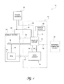
- Figure 1 is a block diagram of an exemplary control and monitoring system
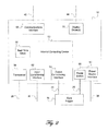
- Figure 2 is a block diagram of an exemplary wake-up circuit
- Figure 3 is an exemplary state diagram of a state machine executed by a computing device in the wake-up circuit.
- like components are numbered the same in each figure, such that the same number on multiple figures represents the same type of component although the specific implementation may be different.
- a diagnostic system may be used to retrieve data from an electronic control unit, such as an engine control module of a vehicular electronic system.
- the diagnostic system may include a wake-up circuit for enabling operation of an electronic device, such as a data logger or an instrumentation device, with at least the capability of a data retrieval device.
- the operation of the electronic device (“data logger”) may be enabled at a time before an electronic control unit (“ECU”) under test begins to output valuable start-up information.
- Data loggers may require a period of time in the form of a start-up time to perform a boot sequence before data collection begins.
- the wake-up circuit mitigates the start-up time by enabling the data logger in advance of anticipated ECU operation, or at the earliest indication that the ECU is about to begin outputting data. As a result, the opportunity to capture all of the data outputted from the ECU is maximized.
- the wake-up circuit may additionally be configured to protect against unintentional power source depletion by the diagnostic system.
- the wake-up circuit may disable (e.g.., apply a disabling signal) or disenable (e.g., remove a previously-applied enable signal) operation of the data logger based upon an indication that a power source is reaching or has reached a depleted state.
- the wake-up circuit may further bring itself to a low power state, based on criteria such as a status of the power source or an elapsed time, such that the wake-up circuit in that low power state draws a reduced amount of current. As discussed below, one or more lower power states may be implemented.
- system 10 illustrates an exemplary control and monitoring system, in which a diagnostic system 12 monitors a controller such as an ECU 14.
- the diagnostic system 12 includes a data logger 16 for at least the retrieving and storing of data from the ECU 14.
- a wake-up circuit 18 enables, disables or disenables the data logger 16 under certain conditions.
- the wake-up circuit 18 may be configurable through a computing device such as an external computing device 20, and may be in communication with a display device 22.
- a power source 24 provides power to the diagnostic system 12 and may also provide power to a vehicle system 26 and/or to the ECU 14.
- the ECU 14 is part of a vehicle system 26; however, the diagnostic system 12 is not limited to monitoring the ECU 14 in a vehicle system 26, but may instead be used to monitor an ECU 14 in other settings.
- An ECU 14 that is used in a vehicle system 26 may be any type of electronic module, including but not limited to an engine control module. There may be multiple ECUs 14 in the vehicle system 26. The diagnostic system 12 may monitor multiple ECUs 14 substantially simultaneously.
- the vehicle system 26 may include a communications bus 28, representing communication between two or more devices.
- the term "communications bus” may encompass the physical structure of a communication link, hardware protocols of the physical link, software protocols for communications across the link, or any combination thereof.
- the communications bus 28 may be based on SAE J1708, SAE J1850, ISO 11898, ISO 9141-2, Keyword 2000, or Controller Area Network (CAN) (e.g., SAE J1939) vehicle-communication protocols, Flexray, Bluetooth, WiFi, WiMax, or any other wired or wireless standard or proprietary protocol.
- the communications bus 28 may also represent a plurality of buses that use the same protocol or different protocols, and that may or may not be in communication with each other.
- System 10 and vehicle system 26 do not require a communications bus 28; it is shown as part of the vehicle system 26 to illustrate a familiar vehicle implementation, for a better understanding of one of the possible system 10 implementations.
- connection may represent multiple types of interfaces, each of which may be unidirectional or bidirectional, may be wired or wireless, and may use any method of communication.
- a connection may be a type of communication bus 28, or may be one or more discrete or analog signals, or may be a combination of a communication bus, discrete signals, and analog signals.
- the physical implementation of the connections includes the use of metal, optic fiber, ceramic or other wired conductors, or radio, infrared, ultrasound or other frequency wireless transmissions.
- System 10 may include more or less connections than shown in Figure 1 .
- the ECU 14 may be in communication with the bus 28 via connection 30; however, such communication is not necessary for the operation of the diagnostic system.
- the data logger 16 retrieves information from the ECU 14 and from other sources within the vehicle system 26 over a connection 32.
- the data logger 16 may have the functionality of an instrumentation system, such that it not only retrieves and logs information from the ECU 14 but also may interact with the ECU 14 to modify operation of the ECU 14.
- the data logger 16 may be capable of analyzing and/or interpreting data from the ECU 14, and may include a display device or may be connected to a display device (not shown.)
- the data logger 16 may be any device capable of the functions described, such as a computing device, including but not limited to a laptop computer.
- the data logger 16 is connected to the wake-up circuit 18 through one or both of a connection 34 and a power feed 35.
- Power feed 35 is any appropriate connection for providing power in the diagnostic system 12 as designed, including but not limited to wire made of a conductive material, an inductive connection, printed circuit board traces, nuts, bolts, screws, locating pins, etc., or some combination thereof, and including multiple instantiations.
- the wake-up circuit 18 may monitor information from the vehicle system 26, including from ECU 14. When the information received satisfies predefined criteria, the wake-up circuit 18 may perform an action related to the data logger 16. The wake-up circuit 18 may also perform actions related to the data logger 16 based on other information, such as information regarding the power source, or other information received internally or externally. Actions taken by the wake-up circuit with respect to the data logger 16 may include sending an enable signal, removing an enable signal, sending a disable signal or removing a disable signal over connection 34. Enabling/disabling may also include enabling or disabling power going to the data logger 16 over power feed 35, as described in more detail below.
- Information regarding the power source 24 may be obtained by the wake-up circuit 18 by monitoring power source 24 information over a connection 38 from the power source 24, or by monitoring the power source 24 voltage, current or other power source 24 information over a power feed 39.
- the connection 38 separate from the power feed connection 39, may be included in the diagnostic system 12 between the wake-up circuit 18 and the power source 24 to allow for communication, such as status queries from the wake-up circuit 18 to the power source 24 or status updates from the power source 24 to the wake-up circuit 18. Communication of information other than status is also possible over connection 38.
- Power feed 39 may be any connection appropriate for the system 10 as designed.
- the power source 24 information includes the power source 24 health condition information.
- the wake-up circuit 18 may take actions with respect to the data logger 16 as described above.
- Predefined criteria may include thresholds. For example, if power source 24 voltage falls below a low-voltage threshold, or power source 24 current falls below a low-current threshold, a criterion may be satisfied.
- Predefined criteria may be related to voltage and/or current trends that tend to indicate a decline or improvement in the health of the power source 24. The predefined criteria are not limited by these examples.
- the wake-up circuit 18 may put itself into a low power state. Alternatively, the wake-up circuit 18 may transition itself into a sequence of lower power states corresponding to progressively more critical power source 24 health. The wake-up circuit 18 may transition itself out of a low power state when the power source 24 health has recovered to a condition satisfactory for the transition.
- the determinations that the power source 24 is in, is approaching, or is recovering from a critical health state may each be made based on the predefined criteria mentioned above with respect to monitoring the power source, or may be based on different or additional criteria of the same or different type.
- the power source 24 is shown in Figure 1 as sourcing power to both the diagnostic system 12 and to the vehicle system 26 system through connections 39 and 40, respectively. However, both the diagnostic system 12 and the vehicle system 26 may be sourced from independent or interconnected power sources.
- the power source 24 may be a single source or multiple sources, and may include self-diagnostic capability.
- the power source 24 may also include a computing device and communication capability, for communication over a communications bus such as communications bus 28, or for communication over connection 38. The particular structure and capability of power source 24 will depend on the particular implementation of the system 10.
- the power source 24 for a vehicle system 26 may be one or more batteries.
- the wake-up circuit 18 power monitoring functionality is advantageously used in battery-powered systems, where a diagnostic system 12 can undesirably drain a battery when left powered for extended periods of time.
- the wake-up circuit 18 may be configurable through the external computing device 20. Configuration may include defining the criteria used by the wake-up circuit 18 to determine when to enable, disable or disenable the data logger 16 or when to put the wake-up circuit 18 into a low power state.
- the external computing device 20 may communicate with the wake-up circuit 18 for purposes other than configuration; for example, the wake-up circuit 18 may provide status indicators or other data to the external computing device 20.
- the wake-up circuit 18 and the external computing device 20 are connected through a connection 42.
- the connection 42 is any connection appropriate for communication with the selected external computing device 20.
- the wake-up circuit 18 may further be configurable through any of the connections 28, 34, 35, 36, 38, 39, 42 or 44.
- the wake-up circuit 18 may further be connected to a display device 22 through a connection 44.
- the display device 22 is shown in Figure 1 as part of the diagnostic system 12; however, the display device 22 may alternatively be external to the diagnostic system 12.
- the display device 22 may allow for a visual representation of information received or generated by the wake-up circuit 18, and may include a user interface for bidirectional communication between the wake-up circuit 18 and the display device 22.
- the connection 44 is any connection appropriate for communication with the selected display device 22.
- the wake-up circuit 18 may be a stand-alone module, or may be a daughter board physically located within the ECU 14 or within the data logger 16, or within any other device, including a device not shown in Figure 1 .
- the data logger 16 may receive power, an enable signal, and a disable signal from the wake-up circuit 18 and/or from other sources.
- the data logger 16 may include a state machine for setting priority for the power, enable signal, and disable signal. Such a state machine is dependent on the hardware and software structure of the data logger 16, as well as the defined power management strategy for the system 10.
- An exemplary wake-up circuit 18 may include a programmable internal computing device 50, an output conditioning interface 52, a power switch 58, a power source interface 60, an input conditioning interface 62, a transceiver 64, a real time clock 66, a communications interface 68, and display drivers 70. These components will be described individually below. Each of these components may in turn include various sub-components. Furthermore, the entire wake-up circuit, or portions of it, may be implemented in one or more integrated circuit (IC) chip, or may be implemented in one or more Field Programmable Gate Array (FPGA) or other programmable hardware device. The wake-up circuit 18 may include more or less functionality than indicated by Figure 2 and may depend in part on a particular implementation.
- IC integrated circuit
- FPGA Field Programmable Gate Array
- the internal computing device 50 may be implemented as a circuit based upon any combination of one or more of the set of: programmable microcontroller, Application Specific Integrated Circuit (ASIC) and Field Programmable Gate Array (FPGA).
- the internal computing device may alternatively be any other device with capabilities as discussed.
- the internal computing device 50 executes at least a state machine 100 (shown in Figure 3 ).
- the state machine 100 may be implemented in software, or may alternatively be part of the physical structure of the internal computing device 50.
- the state machine 100 as executed by the internal computing device 50, defines at least in part the behavior of the wake-up circuit 18.
- the output conditioning interface 52 is connected to the data logger 16 via connection 34 and power feed 35. In response to instructions from the internal computing device 50, the output conditioning interface may output a signal to the data logger 16. Instructions from internal computing device 50 to output conditioning interface 52 may be in the form of serial data, or may be in the form of other digital or analog signals. Output conditioning may include, but is not limited to, any or all of such functions as filtering, adding voltage offsets, providing hysteresis, performing voltage or current scaling, providing isolation, and translating between protocols.
- the internal computing device 50 issues an instruction to the output conditioning interface 52 to enable the data logger 16.
- the output conditioning interface 52 responds by outputting an enable signal to the data logger 16 over connection 34.
- the internal computing device 50 issues an instruction to the output conditioning interface 52 to wake up the data logger 16.
- the output conditioning interface 52 responds by outputting a wake-up signal to the data logger 16 over connection 34.
- the internal computing device 50 issues an instruction to activate a power switch 58 that connects the power source 24 to the data logger 16 over connection 35.
- This instruction may go directly to the power switch 58, or to a power source interface 60 to activate the power switch 58.
- the power switch 58 may also be used to switch power to devices other than the data logger 16.
- the power source interface 60 is connected to the power source 24 via connection 38, and may provide a direct connection between the power source 24 and the power switch 58, or alternatively may include circuitry between the power source 24 and the power switch 58.
- the power switch 58 may comprise one or more discrete components or integrated circuits, or some combination of discrete components and integrated circuits.
- the power source interface 60 may provide circuit protection and/or filtering on the power input from power source 24, and may include circuitry for switching power to other portions of the wake-up circuit 18, or for switching power to other devices not shown. Additionally, the power source interface 60 may include circuitry for setting the wake-up circuit 18 into one or more low power states.
- the power source interface 60 may include the capability to recognize a power source 24 health condition. For example, power source interface 60 may recognize a low voltage or current condition. Recognition of a power source 24 health condition may also be performed partly or wholly by the internal computing device 50.
- the input conditioning interface 62 of the wake-up circuit 18 may include discrete components or integrated circuits or some combination of discrete components and integrated circuits. Signals from the vehicle system 26 are received at the input conditioning interface 62 via connection 36 and conditioned to be usable by the internal computing device 50 or other circuits. Signals may be provided to the internal computing device or other circuits in the form of serial data, or in the form of analog or digital signals. Input conditioning may include, but is not limited to, any or all of such functions as filtering, adding voltage offsets, providing hysteresis, performing voltage or current scaling, providing isolation, and translating between protocols.
- the transceiver 64 provides an interface between the vehicle system 26 communications bus 28 and the internal computing device 50. Transceivers are known for translating protocols from both a software perspective and a hardware perspective.
- the transceiver 64 may perform software and/or hardware translation, and may comprise discrete components or integrated circuits or some combination of discrete components and integrated circuits.
- the real time clock 66 keeps track of time. It may track time absolutely, by communicating with, for example, a global positioning system (GPS). Absolute time may then be available from the real time clock 66 by year, month, week, day, hour, minute, second, and divisions of seconds, for example. Alternatively, the real time clock 66 may track time relatively, providing elapsed time as measured from a predefined event occurrence. The real time clock 66, whether it tracks time absolutely or relatively, is selected based on the resolution and accuracy required by the wake-up circuit 18.
- GPS global positioning system
- the real time clock 66 may include a signal output providing time information that signals the internal computing device 50 or other device that a certain time has been reached or that a certain time has elapsed or that a time event has occurred. Alternatively, the real time clock 66 may provide time information in response to a request. Time information may be encoded for efficient transmission and computation purposes.
- the real time clock 66 may be a stand-alone device within wake-up circuit 18, or may be integrated with the internal computing device 50, or integrated with any other circuitry of wake-up circuit 18. Alternatively, the real time clock may be located external to the wake-up circuit.
- the real time clock 66 may have a dedicated power source such that the real time clock 66 may continue tracking time when the rest of the wake-up circuit 18 is unpowered or in a low power state.
- Time information such as that described with respect to the real time clock 66, may alternatively be received by the wake-up circuit from a source other than the real time clock 66, and may, for example, be received over the input conditioning interface 62.
- the communications interface 68 may be a telecommunications standard such as Recommended Standard 232 (RS232) for communicating with an external computing device 20 having a software configuration utility.
- the software configuration utility may be used to define system settings and variables, and may allow a user of the diagnostic system 12 to define a logical combination of inputs that will cause the wake-up circuit 18 to perform an action with respect to the data logger 16, including inputs such as timeout values or message content received over a message-based connection.
- the software configuration utility may be used to define how data is displayed on the display device 22 by display driver 70.
- the settings may be downloaded to the wake-up circuit 18 and stored on an on-board non-volatile memory device that may be integrated within the internal computing device or may be a stand-alone device (not shown).
- the wake-up circuit 18 may be disconnected from the external computing device 20 and begin autonomous operation. The wake-up circuit 18 may later be reconnected to the external computing device 20 to allow modification of these settings.
- the display driver 70 may be configured to output a status to the display device 22 for viewing during diagnostic testing.
- the display driver drives, via a 3.3 Volt pulse width modulation (PWM) signal, a display device 22 that includes light emitting diodes (LEDs).
- PWM pulse width modulation
- the display driver 70 may also include a bi-directional connection to the display device 22 to provide for a user interface at the display.
- the data logger 16 may perform a boot sequence, and then begin collecting data after the boot sequence is completed.
- a boot sequence may include, but is not limited to, changing the data logger 16 default settings to predefined initial system operation settings, establishing synchronization with external communication buses such as communications bus 28, setting outputs to a known state, and reading inputs to determine current system state.
- the boot sequence takes time to perform, and it is desirable to complete this sequence before the ECU 14 under test begins operation, so that the data logger 16 is able to monitor the ECU 14 during the ECU 14's start-up phase.
- the wake-up circuit 18 may enable the monitoring function of the data logger 16 under various conditions and based on received information.
- the wake-up circuit 18 enables the data logger 16 based on time information.
- the real time clock 66 may signal the internal computing device 50 to enable or power the data logger 16.
- the internal computing device 50 may be configured to receive a current absolute or relative time from the real time clock 66 and compare the current time to a predefined wake-up time.
- time information is received from a source other than the real time clock 66. Based on time information from the real time clock 66 or other source, the internal computing device 50 may instruct the output conditioning interface 52 to enable the data logger 16, via a trigger signal on connection 34 or by applying power on power feed 35.
- the wake-up circuit 18 may also disable the data logger 16 based on time information. For example, if the ECU 14 has been inactive for a predefined time period, the wake-up circuit 18 may send a disable signal to, or remove an enable signal from, the data logger 16, or may switch the power to the data logger 16 off.
- the wake-up circuit 18 may monitor traffic on a communications bus 28, and enable or power the data logger 16 in response to detected message traffic.
- the internal computing device 50 may be configured to monitor the communications bus 28 via the network transceiver 64, to detect when any message, or a particular message, or one of a set of particular messages is present on the communications bus 28.
- the internal computing device 50 may further be configured to instruct enablement or powering of the data logger 16 upon detection of a message that meets predefined criteria.
- the message transmitted may include an identification block and a content block, and the internal computing device 50 may instruct enablement or powering of the data logger 16 based on the information contained in the identification block, in the content block or in both.
- the identification block may include information about the type of message being transmitted, while the content block may include the actual content of the message. For instance, in an automotive application, the identification block may indicate that the message transmitted relates to vehicle system 26 speed, while the content block includes the encoded numerical value of current vehicle system 26 speed.
- the wake-up circuit 18 may also disable the data logger 16 based on a communications bus 28 status or message information. For example, if the communications bus 28 has been inactive for a predefined time period, or if a sleep message is received, the wake-up circuit 18 may send a disable signal to, or remove an enable signal from, the data logger 16, or may switch the power to the data logger 16 off.
- the wake-up circuit 18 may monitor signals received through the input conditioning interface 62 via connection 36. For example, when the voltage of a signal received at the input conditioning interface 62 crosses a predefined threshold, the wake-up circuit 18 may enable or power the data logger 16.
- One implementation of this approach is for the input conditioning interface 62 to be connected to a vehicle system 26 interior dome light that turns on when the vehicle system 26 doors are unlocked. When a voltage is detected across the dome light, the wake-up circuit 18 enables or powers the data logger 16.
- the wake-up circuit 18 may monitor the message content of messages received through input conditioning interface 62 if the interface includes a serial data interface. The wake-up circuit 18 may also be configured to compare the strength of signals transmitted by one or more ECUs 14, and instruct enablement or powering of the data logger 16 if the comparison meets predefined criteria.
- the wake-up circuit 18 may also disable the data logger 16 based on signals received through the input conditioning interface 62 via connection 36. For example, if a sleep input is received, the wake-up circuit 18 may send a disable signal to, or remove an enable signal from, the data logger 16, or may switch the power to the data logger 16 off.
- the wake-up circuit 18 may also be configured to preserve the power source 24 by operating in one or more low current mode. For example, if the power source 24 voltage drops below a first predefined threshold, the wake-up circuit 18 may be set to a first low power state, in which some of the functionality of the wake-up circuit is disabled to reduce power load. If the voltage drops below a second predefined threshold, the wake-up circuit 18 may be set to a second low power state, in which more of the wake-up circuit is disabled to reduce more power load. Alternatively, there may be additional low power states or no low power states, or the wake-up circuit may be disabled or shut off completely in one of the low power states. In one exemplary approach, the wake-up circuit 18 may return to partial or full function once the voltage exceeds a third predefined level.
- Figure 3 is a state diagram that is an exemplary illustration of the state machine 100 executed by the internal computing device 50 of wake-up circuit 18.
- the wake-up circuit 18 recognizes, in addition to other signals as described below, an ignition (IGN) signal from the vehicle system 26.
- the wake-up circuit 18 provides to or removes from the data logger 16 an enable signal or power feed in response to inputs received through the input conditioning interface 62 or transceiver 64, or in response to a signal from the real time clock 66 or other time information source, or in response to power source 24 health status indicators.
- the internal computing device 50 determines what functions to perform in certain states or transitions of the state machine 100 based on signals and indicators such as these.
- the IGN signal in the state diagram is representative of any signal or indicator that can cause a state transition.
- PWR Power to the wake-up circuit 18
- the PWR indication does not necessarily reflect the status of the vehicle system 26 or of ECU 14, because the wake-up circuit 18 may operate at lower or higher power levels than do other systems.
- the PWR indication on the state diagram also does not necessarily reflect the health condition of the power source 24, because the wake-up circuit 18 may be disconnected from the power source 24, or the wake-up circuit 18 may be operational while the power source 24 is in a non-optimal or a critical state.
- the internal computing device 50 enters the Startup 102 state when power is applied to the previously unpowered wake-up circuit 18. If the internal computing device 50 recognizes an Ignition ON signal while in the Startup 102 state, it transitions to the Powerup 104 state, as indicated by transition T1. The internal computing device 50 transitions to the Awake 106 state when the time spent in the Powerup 104 state exceeds a predefined Powerup Timeout threshold or when an Awake message is received from the external computing device 20 through the communications interface 42, as indicated by transition T2. In the Powerup 104 state or Awake 106 state, the internal computing device 50 may request that the output conditioning interface 52 send an enable signal through connection 34 to the data logger 16 or may request that the power switch 58 be activated.
- the internal computing device 50 will transition from the Awake 106 state to the Shutdown 108 state on receipt of an ignition OFF signal, as represented by transition T3, and will transition from the Shutdown 108 state back to the Awake 106 state on receipt of an ignition ON signal, as represented by transition T4. If no ignition ON signal is received by the internal computing device 50 before the time spent in the Shutdown 108 state exceeds a predefined Shutdown Timeout threshold, the internal computing device 50 will transition to a Pre-idle 110 state, as indicated by transition T5.
- the internal computing device 50 transitions to the Idle 112 state when time spent in the Pre-idle 110 state exceeds a predefined Pre-idle Timeout threshold, as indicated by transition T6.
- the internal computing device 50 may disable or disenable selected circuits of the wake-up circuit 18 by signaling a power regulator (not shown) in the Power Source Interface 60 to switch power off to particular circuits of the wake-up circuit 18 while maintaining power to the internal computing device 50, for example, to reduce the power load.
- the data logger 16 may be disabled or disenabled in the Shutdown 108, Pre-idle 110 or Idle 112 states or in the transition to these states.
- the internal computing device 50 will transition to the Idle 112 state if it recognizes a first predefined power source 24 health condition. These transitions are represented on the state diagram as transitions T7, T8, T9, T10 and T11, respectively.
- the Idle 112 state, or the transition to that state may be implemented, for example, by signaling a power regulator (not shown) in the Power Source Interface 60 to switch power off to particular circuits of the wake-up circuit 18 while maintaining power to the internal computing device 50.
- the data logger 16 may be disabled or disenabled in the Idle 112 state, or in the transition to that state.
- the internal computing device 50 will transition to the Powerup 104 state upon receipt of an ignition ON signal, as indicated by transition T12.
- the internal computing device 50 will transition to the Off 114 state if it recognizes a second predefined power source 24 health condition, as indicated by transition T13, and will transition back to the Idle 112 state if it recognizes a third predefined power source 24 health condition, as indicated by transition T14.
- the first, second and third predefined power source 24 health conditions may be, for example, that the power source 24 voltage has crossed a threshold voltage level. All three health conditions may be the same condition, although there should be some hysteresis built in between the second and third health condition to prevent the wake-up circuit 18 from cycling between the Idle 112 and Off 114 states.
- the criteria for establishing that the power source 24 is in one of the three health conditions may be established through configuration by the external computing device 20, as discussed above.
- the transition T15 indicates that power may be removed from the wake-up circuit 18 in the Off 114 state, and then when power is re-applied, the wake-up circuit restarts in the Startup 102 state.
- the state diagram of Figure 3 is for illustration only. Many other states and transitions may be included in the state machine. Likewise, not all of the states and transitions shown must be used. For example, power source 24 health conditions may not be monitored at all, and transitions to low power states may then be based on, e.g., timing information.
- Computing devices such as the internal computing device 50 and external computing device 20, may generally include applications, which may be software applications tangibly embodied as a set of computer-executable instructions on a computer readable medium within the computing device.
- a computing device may be any one of a number of computing devices, such as a personal computer, handheld computing device, cellular telephone, embedded microprocessor, etc.
- Computing devices may employ any of a number of computer operating systems, including, but not limited to, known versions and/or varieties of the Microsoft Windows® operating system, the Unix operating system (e.g., the Solaris® operating system distributed by Sun Microsystems of Menlo Park, California), the AIX UNIX operating system distributed by International Business Machines of Armonk, New York, and the Linux operating system.
- Computing devices generally each include instructions executable by one or more devices such as those listed above.
- Computer-executable instructions may be compiled or interpreted from computer programs created using a variety of programming languages and/or technologies, including, without limitation, and either alone or in combination, JavaTM, C, C++, Visual Basic, Java Script, Perl, etc.
- a processor e.g., a microprocessor
- receives instructions e.g., from a memory, a computer-readable medium, etc., and executes these instructions, thereby performing one or more processes, including one or more of the processes described herein.
- Such instructions and other data may be stored and transmitted using a variety of known computer-readable media.
- the diagnostic system 12 may include a variety of hardware and/or software, and communicate with one or more computer servers associated with a relational database management system (RDBMS) from which data may be extracted.
- RDBMS relational database management system
- the diagnostic system 12 may also represent other mechanisms for providing data, such as data stored in one or more files and obtained via file transfer protocol (FTP) or the like, data obtained from a computer-readable medium such as a disk or tape, or even manual entry of data, among other possible mechanisms.
- FTP file transfer protocol
- the precise number and type of computer servers included in the diagnostic system 12 is not crucial. Further, it is not crucial that any of the information be stored in any particular data store.
- the diagnostic system 12 may be configured to a variety of architectures.
- Data stores may be associated with various computing devices and may include a relational database management system (RDBMS).
- RDBMS generally employs Structured Query Language (SQL) in addition to a language for creating, storing, editing, and executing stored procedures, such as the PL/SQL language mentioned above.
- SQL Structured Query Language
- data stores associated with a computing device may be some other kind of database such as a hierarchical database, a set of files, and an application database in a proprietary format, etc.
- a data store often includes a computing device employing a computer operating system such as one of those mentioned above, and are accessed via a network in any one or more of a variety of manners, as is well known.
- State machine 100 may be generally tangibly embodied as one or more sets of computer-executable instructions stored on a computer-readable medium.
- Such computer readable-medium may be included in or associated with one or more computing devices, even if such devices are not illustrated in the Figures. The method steps accordingly generally execute within one or more such computing devices.
- a computer-readable medium includes any medium, including a tangible medium, which participates in providing data (e.g., instructions), which may be read by a computer. Such a medium may take many forms, including, but not limited to, non-volatile media, and volatile media.
- Non-volatile media include, for example, optical or magnetic disks and other persistent memory.
- Volatile media include dynamic random access memory (DRAM), which typically constitutes a main memory.
- DRAM dynamic random access memory
- tangible computer-readable media include, for example, floppy disk, flexible disk, hard disk, magnetic tape, any other magnetic medium, a CD-ROM, DVD, any other optical medium, punch cards, paper tape, any other physical medium with patterns of holes, a RAM, a PROM, an EPROM, a FLASH-EEPROM, any other memory chip or cartridge, or any other medium from which a computer can read.
- the tangible computer-readable medium may include instructions for performing any of the steps previously recited. However, it is to be appreciated that the tangible computer-readable medium may include instructions for performing steps other than those recited. It is to be further appreciated that some of steps may be performed by the computer, whereas other steps may be performed by a person or another computer.
- Transmission media may include coaxial cables, copper wire, and fiber optics, including the wires that comprise a system bus coupled to a processor. Transmission media may include or convey acoustic waves, light waves and electromagnetic emissions, such as those generated during radio frequency (RF) and infrared (IR) data communications.
- RF radio frequency
- IR infrared
Landscapes
- Engineering & Computer Science (AREA)
- Theoretical Computer Science (AREA)
- General Engineering & Computer Science (AREA)
- Physics & Mathematics (AREA)
- General Physics & Mathematics (AREA)
- Computer Hardware Design (AREA)
- Computing Systems (AREA)
- Debugging And Monitoring (AREA)
- Power Sources (AREA)
- Test And Diagnosis Of Digital Computers (AREA)
Applications Claiming Priority (2)
| Application Number | Priority Date | Filing Date | Title |
|---|---|---|---|
| US11682408P | 2008-11-21 | 2008-11-21 | |
| US12/476,233 US8174382B2 (en) | 2008-11-21 | 2009-06-01 | Diagnostic system having a wake-up circuit |
Publications (2)
| Publication Number | Publication Date |
|---|---|
| EP2189948A2 true EP2189948A2 (fr) | 2010-05-26 |
| EP2189948A3 EP2189948A3 (fr) | 2012-08-01 |
Family
ID=41560702
Family Applications (1)
| Application Number | Title | Priority Date | Filing Date |
|---|---|---|---|
| EP09161686A Ceased EP2189948A3 (fr) | 2008-11-21 | 2009-06-02 | Système de diagnostic comprenant un circuit de réveil |
Country Status (2)
| Country | Link |
|---|---|
| US (1) | US8174382B2 (fr) |
| EP (1) | EP2189948A3 (fr) |
Cited By (6)
| Publication number | Priority date | Publication date | Assignee | Title |
|---|---|---|---|---|
| EP2682919A1 (fr) * | 2012-07-06 | 2014-01-08 | Softing AG | Dispositif de diagnostic pour véhicule automobile |
| CN105981255A (zh) * | 2014-02-12 | 2016-09-28 | 丰田自动车株式会社 | 电力授受控制装置 |
| EP3104338A1 (fr) * | 2015-06-12 | 2016-12-14 | Continental Automotive GmbH | Dispositif de bord pour un véhicule |
| ITUA20164800A1 (it) * | 2016-06-30 | 2017-12-30 | Octo Telematics Spa | Procedimento per la stima della durata di un viaggio di un veicolo basato sulla determinazione dello stato del veicolo. |
| WO2021037968A1 (fr) * | 2019-08-30 | 2021-03-04 | Jaguar Land Rover Limited | Diagnostics de véhicule partiels |
| GB2594250A (en) * | 2020-04-20 | 2021-10-27 | Continental Automotive Gmbh | Electronic device and method of responding to a trigger to wake up |
Families Citing this family (40)
| Publication number | Priority date | Publication date | Assignee | Title |
|---|---|---|---|---|
| US6437692B1 (en) * | 1998-06-22 | 2002-08-20 | Statsignal Systems, Inc. | System and method for monitoring and controlling remote devices |
| US9262777B2 (en) | 2002-02-05 | 2016-02-16 | Square, Inc. | Card reader with power efficient architecture that includes a wake-up circuit |
| US9262757B2 (en) * | 2002-02-05 | 2016-02-16 | Square, Inc. | Method of transmitting information from a card reader with a power supply and wake-up circuit to a mobile device |
| US9305314B2 (en) * | 2002-02-05 | 2016-04-05 | Square, Inc. | Methods of transmitting information to mobile devices using cost effective card readers |
| US9495676B2 (en) | 2002-02-05 | 2016-11-15 | Square, Inc. | Method of transmitting information from a power efficient card to a mobile device |
| US9224142B2 (en) | 2002-02-05 | 2015-12-29 | Square, Inc. | Card reader with power efficient architecture that includes a power supply and a wake up circuit |
| US9286635B2 (en) | 2002-02-05 | 2016-03-15 | Square, Inc. | Method of transmitting information from efficient communication protocol card readers to mobile devices |
| DE102009015197A1 (de) | 2009-03-31 | 2010-10-14 | Volkswagen Ag | Steuergerät für ein Fahrzeugnetzwerk und Verfahren zum Betreiben eines Fahrzeugnetzwerkes |
| JP5002627B2 (ja) * | 2009-08-25 | 2012-08-15 | 日立オートモティブシステムズ株式会社 | 電源制御装置 |
| WO2012018733A2 (fr) * | 2010-08-03 | 2012-02-09 | Spx Corporation | Diagnostic de véhicule, système de communication et de transmission de signal |
| US9576159B1 (en) | 2011-01-24 | 2017-02-21 | Square, Inc. | Multiple payment card reader system |
| US8653954B2 (en) * | 2011-04-26 | 2014-02-18 | General Motors Llc | Systems and methods for detecting an error in the installation of an electrical component |
| DE102011079412A1 (de) * | 2011-07-19 | 2013-01-24 | Robert Bosch Gmbh | Verfahren und Vorrichtung zum Abspeichern einer Weckinformation in Teilnehmern eines CAN-Bussystems |
| DE102011084963A1 (de) * | 2011-10-21 | 2013-04-25 | Robert Bosch Gmbh | Vorrichtung und Verfahren zum sicheren Erkennen von Weckereignissen in der Phase des Abschaltens eines Steuergerätes |
| US9008907B2 (en) | 2013-05-31 | 2015-04-14 | Hugh D Copeland | Intelligent vehicle power control system and method |
| US8910868B1 (en) | 2013-11-27 | 2014-12-16 | Square, Inc. | Firmware management |
| US9633236B1 (en) | 2013-12-11 | 2017-04-25 | Square, Inc. | Power harvesting in reader devices |
| US8931699B1 (en) | 2013-12-11 | 2015-01-13 | Square, Inc. | Bidirectional audio communication in reader devices |
| US9256769B1 (en) | 2014-02-25 | 2016-02-09 | Square, Inc. | Mobile reader device |
| US9390569B2 (en) * | 2014-05-16 | 2016-07-12 | GM Global Technology Operations LLC | Control and diagnosis of a controller wake up feature |
| US10304043B1 (en) | 2014-05-21 | 2019-05-28 | Square, Inc. | Multi-peripheral host device |
| USD762651S1 (en) | 2014-06-06 | 2016-08-02 | Square, Inc. | Mobile device case |
| US9760740B1 (en) | 2014-06-23 | 2017-09-12 | Square, Inc. | Terminal case with integrated dual reader stack |
| US9256770B1 (en) | 2014-07-02 | 2016-02-09 | Square, Inc. | Terminal case with integrated reader and shortened base |
| US9799025B2 (en) | 2014-08-19 | 2017-10-24 | Square, Inc. | Energy harvesting bidirectional audio interface |
| US9355285B1 (en) | 2015-02-12 | 2016-05-31 | Square, Inc. | Tone-based wake up circuit for card reader |
| CN109690574B (zh) * | 2016-08-11 | 2022-04-01 | 大唐移动通信设备有限公司 | 用于按需移动设备访问的方法和装置 |
| DE102018112812B4 (de) * | 2017-05-31 | 2024-11-21 | Steering Solutions Ip Holding Corporation | Spieldetektionsdiagnose beim starten |
| US10410021B1 (en) | 2017-12-08 | 2019-09-10 | Square, Inc. | Transaction object reader with digital signal input/output and internal audio-based communication |
| US11087301B1 (en) | 2017-12-19 | 2021-08-10 | Square, Inc. | Tamper resistant device |
| KR102796850B1 (ko) * | 2018-11-15 | 2025-04-15 | 현대자동차주식회사 | 차량의 통신 시스템 및 그 제어방법 |
| EP3888223A4 (fr) * | 2018-11-29 | 2022-08-10 | Club Car, LLC | Système de commande de véhicule utilitaire comprenant une horloge en temps réel |
| JP7183745B2 (ja) * | 2018-11-30 | 2022-12-06 | 株式会社デンソー | 電子制御装置 |
| US11639142B2 (en) * | 2019-01-11 | 2023-05-02 | Ford Global Technologies, Llc | Electronic control module wake monitor |
| CN113271000B (zh) * | 2021-04-28 | 2023-06-02 | 精进电动科技股份有限公司 | 一种唤醒使能电路和电机控制器 |
| CN113911031B (zh) * | 2021-10-08 | 2022-11-15 | 东风汽车集团股份有限公司 | 电子外后视镜的时序控制方法、电子设备及存储介质 |
| KR102784708B1 (ko) * | 2021-11-23 | 2025-03-19 | 주식회사 엘지에너지솔루션 | 전기 차량을 위한 차량 진단 디바이스 |
| WO2023168488A1 (fr) * | 2022-03-09 | 2023-09-14 | Element Engineering Australia Pty Ltd | Enregistreur de données |
| US20240092220A1 (en) * | 2022-09-15 | 2024-03-21 | GM Global Technology Operations LLC | Key-off electrical load management for a vehicle |
| CN116729300B (zh) * | 2023-07-31 | 2024-05-03 | 中国第一汽车股份有限公司 | 一种数据处理芯片的供电模块及其控制方法和一种车辆 |
Family Cites Families (27)
| Publication number | Priority date | Publication date | Assignee | Title |
|---|---|---|---|---|
| JPS61288217A (ja) * | 1985-06-14 | 1986-12-18 | Sharp Corp | システムウエイクアツプ方式 |
| NL8702749A (nl) * | 1987-11-18 | 1989-06-16 | Philips Nv | Afstandsbedieningssysteem met ontwaak signaal. |
| US4942393A (en) * | 1988-05-27 | 1990-07-17 | Lectron Products, Inc. | Passive keyless entry system |
| US4950913A (en) * | 1989-04-21 | 1990-08-21 | Kephart David A | Programmable timer power switch unit |
| FR2660769B1 (fr) * | 1990-04-06 | 1994-09-23 | Neiman Sa | Circuit de reveil d'alimentation de microprocesseur, notamment pour une carte d'identification d'un ensemble de telecommande d'automobile. |
| US5272386A (en) * | 1992-02-14 | 1993-12-21 | Kephart David A | Programmable timer power switch unit with emergency override reset |
| US5563452A (en) * | 1992-07-22 | 1996-10-08 | Kephart; David A. | Control unit for vehicle-borne electrical equipment |
| US5790946A (en) * | 1993-07-15 | 1998-08-04 | Rotzoll; Robert R. | Wake up device for a communications system |
| EP1266802B1 (fr) * | 1995-05-24 | 2003-11-12 | Hitachi, Ltd. | Système et méthode de commande électronique pour véhicule |
| US5621250A (en) * | 1995-07-31 | 1997-04-15 | Ford Motor Company | Wake-up interface and method for awakening an automotive electronics module |
| US5675811A (en) * | 1995-08-18 | 1997-10-07 | General Magic, Inc. | Method for transmitting information over an intelligent low power serial bus |
| DE19611942C2 (de) * | 1996-03-26 | 2003-02-20 | Daimler Chrysler Ag | Halbleiterschaltkreis für ein elektronisches Steuergerät |
| DE19611944C2 (de) * | 1996-03-26 | 2003-03-27 | Daimler Chrysler Ag | Integrierter Schaltkreis zur Kopplung eines mikrokontrollierten Steuergerätes an einen Zweidraht-Bus |
| US6100814A (en) * | 1996-05-07 | 2000-08-08 | Lear Automotive Dearborn, Inc. | Remote control wake up detector system |
| US5867557A (en) * | 1996-05-17 | 1999-02-02 | Texas Instruments Incorporated | Remotely controlled communication line diagnostic apparatus and method |
| US6198995B1 (en) * | 1998-03-31 | 2001-03-06 | Lear Automotive Dearborn, Inc. | Sleep mode for vehicle monitoring system |
| US6031465A (en) * | 1998-04-16 | 2000-02-29 | Burgess; James P. | Keyless entry system for vehicles in particular |
| US6525648B1 (en) * | 1999-01-29 | 2003-02-25 | Intermec Ip Corp | Radio frequency identification systems and methods for waking up data storage devices for wireless communication |
| US6300879B1 (en) * | 1999-07-22 | 2001-10-09 | Daimlerchrysler Corporation | Wake-up circuit for a remotely located vehicle control module |
| US6738914B2 (en) * | 2001-01-05 | 2004-05-18 | Motorola, Inc. | Method and apparatus for determining whether to wake up a system by detecting a status of a push button switch that is remotely located from the system |
| FR2827056B1 (fr) * | 2001-07-06 | 2003-12-12 | Peugeot Citroen Automobiles Sa | Systeme de reveil de stations associes pour la mise en oeuvre d'au moins une fonction repartie, notamment dans un vehicule automobile |
| US7293188B2 (en) * | 2002-11-12 | 2007-11-06 | Freescale Semiconductor, Inc. | Low voltage detection system |
| JP4032955B2 (ja) * | 2002-12-17 | 2008-01-16 | 株式会社日立製作所 | 自動車用電子制御装置 |
| WO2005091999A2 (fr) * | 2004-03-22 | 2005-10-06 | David Kephart | Unite programmable de gestion d'energie |
| JP4692318B2 (ja) * | 2005-04-20 | 2011-06-01 | 株式会社デンソー | 電子制御装置 |
| US7912381B2 (en) * | 2006-06-02 | 2011-03-22 | Standard Microsystems Corporation | Transmission network having an optical receiver that utilizes dual power pins and a single status pin to lower power consumption, lower manufacturing cost, and increase transmission efficiency |
| US7971086B2 (en) * | 2007-02-06 | 2011-06-28 | D. S. P. Group Ltd. | Integrated waking/while-awake power management system with breaking distance timer for high wake-up latency portion of hardware |
-
2009
- 2009-06-01 US US12/476,233 patent/US8174382B2/en not_active Expired - Fee Related
- 2009-06-02 EP EP09161686A patent/EP2189948A3/fr not_active Ceased
Cited By (17)
| Publication number | Priority date | Publication date | Assignee | Title |
|---|---|---|---|---|
| DE102012106077B4 (de) | 2012-07-06 | 2023-06-01 | Softing Ag | Diagnosevorrichtung für ein Kraftfahrzeug |
| EP2682919A1 (fr) * | 2012-07-06 | 2014-01-08 | Softing AG | Dispositif de diagnostic pour véhicule automobile |
| US10259328B2 (en) | 2014-02-12 | 2019-04-16 | Toyota Jidosha Kabushiki Kaisha | Power-transfer control device for vehicle including power storage device and communication unit |
| CN105981255A (zh) * | 2014-02-12 | 2016-09-28 | 丰田自动车株式会社 | 电力授受控制装置 |
| EP3107178A4 (fr) * | 2014-02-12 | 2017-05-10 | Toyota Jidosha Kabushiki Kaisha | Dispositif de commande de transfert de puissance |
| CN105981255B (zh) * | 2014-02-12 | 2018-12-21 | 丰田自动车株式会社 | 电力授受控制装置 |
| EP3104338A1 (fr) * | 2015-06-12 | 2016-12-14 | Continental Automotive GmbH | Dispositif de bord pour un véhicule |
| CN109952600A (zh) * | 2016-06-30 | 2019-06-28 | 奥克托信息技术股份公司 | 一种用于基于车辆的状态的确定来估计车辆的行驶时间的方法 |
| WO2018002891A1 (fr) * | 2016-06-30 | 2018-01-04 | Octo Telematics S.P.A. | Procédé d'estimation du temps de parcours d'un véhicule sur la base d'une détermination de l'état du véhicule |
| US10984613B2 (en) | 2016-06-30 | 2021-04-20 | Octo Telematics S.P.A. | Method for estimating the travel time of a vehicle based on the determination of the state of the vehicle |
| RU2760756C2 (ru) * | 2016-06-30 | 2021-11-30 | Окто Телематикс С.П.А. | Способ оценки времени в пути транспортного средства на основании определения состояния транспортного средства |
| ITUA20164800A1 (it) * | 2016-06-30 | 2017-12-30 | Octo Telematics Spa | Procedimento per la stima della durata di un viaggio di un veicolo basato sulla determinazione dello stato del veicolo. |
| WO2021037968A1 (fr) * | 2019-08-30 | 2021-03-04 | Jaguar Land Rover Limited | Diagnostics de véhicule partiels |
| US12562013B2 (en) | 2019-08-30 | 2026-02-24 | Jaguar Land Rover Limited | Partial vehicle diagnostics |
| GB2594250A (en) * | 2020-04-20 | 2021-10-27 | Continental Automotive Gmbh | Electronic device and method of responding to a trigger to wake up |
| GB2594250B (en) * | 2020-04-20 | 2024-11-27 | Continental Automotive Tech Gmbh | Electronic device and method of responding to a trigger to wake up |
| US12360582B2 (en) | 2020-04-20 | 2025-07-15 | Continental Automotive Technologies GmbH | Electronic device and method of responding to a trigger to wake up |
Also Published As
| Publication number | Publication date |
|---|---|
| US20100127857A1 (en) | 2010-05-27 |
| US8174382B2 (en) | 2012-05-08 |
| EP2189948A3 (fr) | 2012-08-01 |
Similar Documents
| Publication | Publication Date | Title |
|---|---|---|
| US8174382B2 (en) | Diagnostic system having a wake-up circuit | |
| CN105083168B (zh) | 控制器唤醒特征的控制和诊断 | |
| US20100023198A1 (en) | System and method for emulating vehicle ignition-switched power | |
| CN107306043B (zh) | 充电唤醒装置及充电唤醒装置的控制方法 | |
| US7231285B2 (en) | Data recording apparatus and data recording method | |
| US9372216B2 (en) | Electric power supply controller for vehicle | |
| US10347056B2 (en) | Apparatus and method for monitoring vehicle ON/OFF state | |
| CN104635690A (zh) | 集成网关功能的纯电动汽车的整车控制器 | |
| CN110308400A (zh) | 一种整车下电后蓄电池状态的监控方法 | |
| US11281286B1 (en) | System to wake electronic plug-in devices (EPIDs) and related method(s) thereof | |
| CN117885595A (zh) | 电池管理控制装置、车辆控制系统以及电池管理控制方法 | |
| CN111399405A (zh) | 车载电子设备的控制方法、装置、存储介质、电子设备 | |
| CN1661348B (zh) | 数据记录装置及用于数据记录装置的关机方法 | |
| EP1571599B1 (fr) | Appareil et méthode d'enregistrement de données | |
| CN113815636A (zh) | 一种车辆安全监控方法、装置、电子设备及存储介质 | |
| CN112947165B (zh) | 唤醒电子设备的方法及电子设备 | |
| CN120756389A (zh) | 故障监测方法、电子保险、计算机设备及存储介质 | |
| CN114220250A (zh) | 汽车蓄电池低电压的提醒方法、装置、设备及存储介质 | |
| CN120088881A (zh) | 一种自动驾驶车辆的数据记录系统及方法 | |
| CN113936356B (zh) | 一种行车记录仪的控制方法、装置、行车记录仪和介质 | |
| KR20130008702A (ko) | 차량 모니터링 장치 | |
| CN118114102B (zh) | 车辆的不休眠状态监控方法、装置、电子设备和存储介质 | |
| CN210515030U (zh) | 用于车联网的后台汽车监控系统及监测器 | |
| CN105946742A (zh) | 基于磁场变化唤醒的低功耗车载电子设备及方法 | |
| CN223450341U (zh) | 一种用于车辆轮端温度感知与预警的接收机电路 |
Legal Events
| Date | Code | Title | Description |
|---|---|---|---|
| PUAI | Public reference made under article 153(3) epc to a published international application that has entered the european phase |
Free format text: ORIGINAL CODE: 0009012 |
|
| AK | Designated contracting states |
Kind code of ref document: A2 Designated state(s): AT BE BG CH CY CZ DE DK EE ES FI FR GB GR HR HU IE IS IT LI LT LU LV MC MK MT NL NO PL PT RO SE SI SK TR |
|
| PUAL | Search report despatched |
Free format text: ORIGINAL CODE: 0009013 |
|
| AK | Designated contracting states |
Kind code of ref document: A3 Designated state(s): AT BE BG CH CY CZ DE DK EE ES FI FR GB GR HR HU IE IS IT LI LT LU LV MC MK MT NL NO PL PT RO SE SI SK TR |
|
| RIC1 | Information provided on ipc code assigned before grant |
Ipc: G06F 1/32 20060101ALI20120627BHEP Ipc: G07C 5/08 20060101AFI20120627BHEP |
|
| 17P | Request for examination filed |
Effective date: 20130131 |
|
| 17Q | First examination report despatched |
Effective date: 20130522 |
|
| STAA | Information on the status of an ep patent application or granted ep patent |
Free format text: STATUS: THE APPLICATION HAS BEEN REFUSED |
|
| 18R | Application refused |
Effective date: 20151103 |