EP2189990A1 - module d'enroulement à phase unique et arrangement de modules d'enroulement à phase unique - Google Patents
module d'enroulement à phase unique et arrangement de modules d'enroulement à phase unique Download PDFInfo
- Publication number
- EP2189990A1 EP2189990A1 EP08020348A EP08020348A EP2189990A1 EP 2189990 A1 EP2189990 A1 EP 2189990A1 EP 08020348 A EP08020348 A EP 08020348A EP 08020348 A EP08020348 A EP 08020348A EP 2189990 A1 EP2189990 A1 EP 2189990A1
- Authority
- EP
- European Patent Office
- Prior art keywords
- connection
- phase winding
- winding
- modules
- phase
- Prior art date
- Legal status (The legal status is an assumption and is not a legal conclusion. Google has not performed a legal analysis and makes no representation as to the accuracy of the status listed.)
- Granted
Links
- 238000004804 winding Methods 0.000 title claims abstract description 188
- 125000004122 cyclic group Chemical group 0.000 claims description 9
- 239000004020 conductor Substances 0.000 description 19
- 230000008878 coupling Effects 0.000 description 6
- 238000010168 coupling process Methods 0.000 description 6
- 238000005859 coupling reaction Methods 0.000 description 6
- 239000011347 resin Substances 0.000 description 6
- 229920005989 resin Polymers 0.000 description 6
- XEEYBQQBJWHFJM-UHFFFAOYSA-N Iron Chemical compound [Fe] XEEYBQQBJWHFJM-UHFFFAOYSA-N 0.000 description 4
- 238000010276 construction Methods 0.000 description 4
- 238000010586 diagram Methods 0.000 description 4
- 230000005540 biological transmission Effects 0.000 description 3
- RYGMFSIKBFXOCR-UHFFFAOYSA-N Copper Chemical compound [Cu] RYGMFSIKBFXOCR-UHFFFAOYSA-N 0.000 description 2
- 229910052802 copper Inorganic materials 0.000 description 2
- 239000010949 copper Substances 0.000 description 2
- 229910052742 iron Inorganic materials 0.000 description 2
- 238000004519 manufacturing process Methods 0.000 description 2
- 239000000463 material Substances 0.000 description 2
- 238000003860 storage Methods 0.000 description 2
- 238000005266 casting Methods 0.000 description 1
- 238000011109 contamination Methods 0.000 description 1
- 230000001419 dependent effect Effects 0.000 description 1
- 238000006073 displacement reaction Methods 0.000 description 1
- 230000000694 effects Effects 0.000 description 1
- 230000008030 elimination Effects 0.000 description 1
- 238000003379 elimination reaction Methods 0.000 description 1
- 238000005538 encapsulation Methods 0.000 description 1
- 238000009434 installation Methods 0.000 description 1
- 239000011810 insulating material Substances 0.000 description 1
- 238000009413 insulation Methods 0.000 description 1
- 230000010354 integration Effects 0.000 description 1
- 239000002184 metal Substances 0.000 description 1
- 229910052751 metal Inorganic materials 0.000 description 1
- 238000000034 method Methods 0.000 description 1
- 230000007935 neutral effect Effects 0.000 description 1
- 239000004848 polyfunctional curative Substances 0.000 description 1
- 238000004382 potting Methods 0.000 description 1
Images

Classifications
-
- H—ELECTRICITY
- H01—ELECTRIC ELEMENTS
- H01F—MAGNETS; INDUCTANCES; TRANSFORMERS; SELECTION OF MATERIALS FOR THEIR MAGNETIC PROPERTIES
- H01F29/00—Variable transformers or inductances not covered by group H01F21/00
- H01F29/02—Variable transformers or inductances not covered by group H01F21/00 with tappings on coil or winding; with provision for rearrangement or interconnection of windings
-
- H—ELECTRICITY
- H01—ELECTRIC ELEMENTS
- H01F—MAGNETS; INDUCTANCES; TRANSFORMERS; SELECTION OF MATERIALS FOR THEIR MAGNETIC PROPERTIES
- H01F5/00—Coils
- H01F5/04—Arrangements of electric connections to coils, e.g. leads
-
- H—ELECTRICITY
- H01—ELECTRIC ELEMENTS
- H01F—MAGNETS; INDUCTANCES; TRANSFORMERS; SELECTION OF MATERIALS FOR THEIR MAGNETIC PROPERTIES
- H01F27/00—Details of transformers or inductances, in general
- H01F27/28—Coils; Windings; Conductive connections
- H01F27/32—Insulating of coils, windings, or parts thereof
- H01F27/327—Encapsulating or impregnating
-
- H—ELECTRICITY
- H01—ELECTRIC ELEMENTS
- H01F—MAGNETS; INDUCTANCES; TRANSFORMERS; SELECTION OF MATERIALS FOR THEIR MAGNETIC PROPERTIES
- H01F30/00—Fixed transformers not covered by group H01F19/00
- H01F30/06—Fixed transformers not covered by group H01F19/00 characterised by the structure
- H01F30/12—Two-phase, three-phase or polyphase transformers
Definitions
- the invention relates to a single-phase winding module having at least one first electrical winding, which has two winding ends, and with a plurality of electrical connection devices.
- the invention also relates to an arrangement of single-phase winding modules according to the invention.
- transformers are used in electrical energy supply networks. Their task is to electrically couple network areas with different voltage levels together. Higher voltages, for example 10 kV or 110 kV, are suitable for transmission over longer distances because the electrical transmission losses are reduced due to the lower current flow.
- Electrical power grids are usually designed as three-phase networks, i. as a system of three individual conductors, wherein current and voltage are shifted at a symmetrical network load between the respective conductors by 120 ° to each other.
- transformers in such three-phase networks are also three-phase, ie with at least three windings to perform, but also three-phase windings or inductors are used, for example, to compensate for reactive electrical power.
- transformers in such three-phase networks are also three-phase, ie with at least three windings to perform, but also three-phase windings or inductors are used, for example, to compensate for reactive electrical power.
- To arrange the windings on a common transformer core or on the other hand to connect three single-phase transformers or winding modules to a three-phase transformer bank.
- a delta connection of the transformer windings takes place on the undervoltage side and a star connection with common center conductor on the upper voltage side.
- single-phase winding modules are preferably of identical construction.
- the interconnection of single-phase winding modules to such a transformer bank is usually carried out by external connections, for example by means of copper rods or cables, wherein the interconnection into the desired switching group requires a space-consuming crossing or interchanging of the connecting conductors.
- the single-phase winding module according to the invention is characterized in that at least three electrical connection devices each are arranged in a first connection group and at least three connection devices in an associated second connection group, that between each connection device of the first connection group and each connection devices of the second connection group in each case an electrical connection consists, whereby in each case a connecting device pair is formed, that the arrangement of the connecting devices said terminal pair is cyclically interchanged with each other and that said first coil is connected to said first of its two coil ends with one of said pairs of connectors, and with its second end to another pair of connectors.
- three single-phase winding modules are interconnected, which corresponds exactly to the number of phases in a three-phase network.
- the interconnection is ideally realized in such a way that the second terminal group of a first module is connected to the first terminal group of an adjacent further preferably identical module, whereby an intersection or permutation of the connection conductors due to the cyclic permutation already carried out within the single-phase winding module is avoided.
- each electrical phase of the connected three-phase network is guided differently in each single-phase winding module.
- Each at least one first winding of each single-phase winding module is thus connected to at least one of its two winding ends with a different electrical phase. This provides a three-phase interconnection of the single-phase winding modules.
- connection pairs and the integration of a cyclic permutation of the electrical connection as part of the single-phase winding module of the effort for the respective external interconnection are advantageously reduced and reduced error sources during installation.
- all connecting elements between the modules - such as cables or metal rails - are guided without crossing.
- the further pair of connecting devices is another of the at least three cyclically reversed pairs of connecting devices, such that, when three such single-phase winding modules are connected, a delta connection of these windings results.
- the first and second terminal groups each have a fourth connection device, wherein these fourth connection devices are electrically connected to each other without cyclic permutation.
- the fourth terminal device pair thus formed is respectively connected to the second end of the first winding.
- the geometric arrangement of the connection devices of the first connection group is similar to the geometric arrangement of the connection devices of the second connection group.
- a plurality of identical adjacent single-phase winding modules can be arranged such that the connection devices of the first and second terminal groups of adjacent modules are located exactly opposite each other.
- connection devices of a module are each designed as a recess, for example in the form of a socket, into which a positive connection element, for example a rod-shaped connecting conductor, can be inserted.
- connection conductors After inserting all provided connection conductors, it is particularly easy to connect an adjacent module by lateral movement along the connection conductors. Due to the identical construction of the respective single-phase winding modules whose manufacturing costs are also advantageously reduced.
- the terminal devices of the first and the second terminal groups located opposite one another of adjacent single-phase winding modules can be connected directly to one another by plug-in connections, wherein additional connecting elements are advantageously avoided.
- the connection devices of the first connection group are formed as bush-shaped recesses and the corresponding counterparts of a second connection group of a structurally identical module as a positively molded connector.
- an electrical connection of single-phase winding modules can be realized by simply telescoping the single-phase winding modules associated connection elements and thus further advantageously advantageous.
- the single-phase winding module according to the invention has a third and one associated fourth terminal group and a second electrical winding, wherein the first winding is magnetically coupled to the second winding, which with at least one of its two winding ends with a terminal device pair of the third and fourth connection group is connected.
- a magnetic coupling is realized, for example, by a common arrangement of first and second winding around a magnetic core, for example made of iron. However, this is known to the person skilled in the art from transformer construction.
- Such a single-phase winding module thus has a primary and a secondary winding, which are in a certain gear ratio to each other and can be used as a single-phase transformer.
- the connections of the primary winding are led out here in the first and second terminal group and the terminals of the secondary winding in the third and fourth terminal group. This results in at least six connector pairs.
- each a star or delta circuit of realized first and second windings Depending on whether the respectively second end of the first or second winding of a single-phase winding module is performed on a fourth, non-cyclically reversed connection device pair or on another of the three cyclically reversed connection device pairs of the associated terminal groups, each a star or delta circuit of realized first and second windings.
- the common switching groups of three-phase transformers can be realized by interconnecting three identical single-phase winding modules.
- the respective switching group is predetermined by the respective single-phase winding modules to be interconnected. It is of course also possible to realize in this way a three-phase transformer with a tertiary winding, in which case a fifth and sixth terminal group are still to be arranged. For each star connection of a winding, it is preferable to lead the interconnected star point through a fourth, not cyclically interchanged terminal device pair.
- this is encapsulated with a suitable insulation medium, for example based on a resin.
- a suitable insulation medium for example based on a resin.
- resins are available both as a one-component resin and as a two-component resin with base material and hardener, the latter variant having the advantage of a lower curing temperature of the resin after casting.
- a terminal group can be either a number of individual connection devices, which are arranged without direct connection elements on or in the surface of the single-phase winding module, for example by encapsulation.
- a connection module can also be an assembly with a plurality of connection devices, which is arranged as a group on or in the surface of the single-phase winding module.
- the first winding and / or the second winding are provided for an electrical voltage of at least 1 kV. From this voltage level, the use of three-phase transformers is particularly useful and the advantages of the invention, for example, the reduced effort in the interconnection of modules, comes particularly to fruition.
- single-phase winding modules according to the invention are also advantageous for higher voltages, for example 10kV, 110kV or 380kV.
- the object is also achieved by an arrangement of three single-phase winding modules, which are arranged side by side and electrically connected to each other via the respective terminal groups. Particularly space-saving is the arrangement of the modules along a horizontal or vertical line.
- all single-phase winding modules are identical. On the one hand, this reduces their production costs through synergy effects and also reduces the stock of replacement transformers. In the case of a three-phase transformer, at least one complete replacement transformer is to be provided for storage, whereas in the arrangement according to the invention the storage of a single single-phase winding module is sufficient.
- the arrangement according to the invention more than three, but preferably an integer multiple of three, that is six, nine, twelve, fifteen etc. of such single-phase winding modules interconnected.
- the power of the transformer bank formed by interconnection can be adapted to the respective requirements, for example in the form of an increase in performance in a grid expansion. It is particularly advantageous that always only identical modules are interconnected.
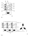
- Fig. 1 shows an exemplary parallelepiped-like first single-phase winding module 10 with a first terminal group 38 and a second terminal group 40 in a schematic sectional view.
- the first terminal group 38 has a first 14, a second 16, a third 18 and a fourth 20 terminal device, which are arranged along a line equidistant and parallel to each other.
- the connecting devices 15, 16, 18, 20 are formed as a rod-shaped elevation of a conductive material, such as copper, similar to a plug.
- the fifth 22, sixth 24, seventh 26 and eighth 28 terminal devices of the associated second terminal group 40 are also arranged along a line at equidistant intervals.
- the first connection device 14 is connected to the sixth connection device 24 via a cyclically exchanged first electrical connection 30
- the second connection device 16 is connected to the seventh connection device 26 via a cyclically exchanged third electrical connection 34
- the third connection device 18 is connected to the fifth connection device 22 via a cyclically exchanged second electrical connection 32.
- the fourth connection device 20 is connected to the eighth connection device 28 via a non-cyclically interchanged fourth connection 36.
- connection devices 22, 24, 26, 28 of the second connection group are each in the form of a sleeve-like recess whose interior is adapted in a form-fitting manner to the plug-like connection devices 14, 16, 18, 20 of the first connection group 38 located opposite.
- the connection devices of the first connection group 38 of the first single-phase winding module 10 can be pushed into the connection devices of a second connection group 40 of a structurally identical single-phase winding module 10, whereby a direct electrical contact between the respective connection devices [14, 16, 18, 20], [22, 24, 26, 28].
- a connector includes a spring-like mechanism that ensures a secure electrical contact even with minor tolerances of the respective connection devices.
- a first winding 12 of the first single-phase transformer 10 is connected at its first end to the cyclically reversed first terminal device pair, which is formed from the third 18 and fifth 22 terminal device.
- the second end of the winding is connected to the fourth non-cyclically exchanged terminal device pair, which is formed from the fourth 20 and eighth 28 terminal devices.
- Fig. 2 shows an exemplary star connection of three identical single-phase winding modules.
- Reference number 112 shows three single-phase winding modules pushed one inside the other, in which the respective second end of the winding conductor of the respective windings X1, X2, X3 is guided onto the common center conductor N1. It is good to see that the connection devices of the individual modules mesh with each other and thus an electrical connection between the single-phase winding modules produce.
- the corresponding electrical equivalent circuit diagram is identified by reference numeral 114.
- Fig. 3 shows in an analogous manner an exemplary delta connection of three identical single-phase winding modules.
- Reference number 122 shows three single-phase winding modules pushed one inside the other, in which the respective second end of the winding conductor of the respective windings X1, X2, X3 is routed to another cyclically reversed connecting device pair.
- Reference number 124 identifies the equivalent electrical equivalent circuit diagram.
- Fig. 4 shows an exemplary interconnection 50 of three identical cuboid single-phase winding modules 52, 54, 56, which are arranged side by side along a line, not shown, to a three-phase transformer.
- Each single-phase winding module 52, 54, 56 has on its one side a first and a third terminal group and on the respective opposite side an associated second or fourth terminal group, wherein the adjacent single-phase winding modules 52, 54, 56 as described Fig. 1 interconnected with each other.
- the single-phase winding modules 52, 54, 56 are assumed to be potted, i. the contour formed from the magnetic core, the windings and the other components is cast with a corresponding resin and, for example, a predominantly cuboid or disc-shaped outer contour is formed.
- the first windings 68, 70, 72 of the single-phase transformer winding modules 52, 54, 56 are electrically connected in delta, the entire interconnection being designated by reference numeral 58.
- a connection of the transformer bank formed by the single-phase transformer winding modules 52, 54, 56 with the first three-phase conductors R1, S1, T1 is connected to the first terminal group of the arranged in an edge position second single-phase transformer winding module 52.
- the first windings 68, 70, 72 of the respective single-phase winding modules 52, 54, 56 are connected via a respective magnetic coupling 80, 82, 84 to the associated second winding 74, 76, 78.
- a magnetic coupling is realized, for example, by a common arrangement of first 80, 82, 84 and second 74, 76, 78 winding around a magnetic core, for example made of iron.
- the transmission ratio between the respective first and second windings is, for example, 1 to 10, as required, for example, for a transformer with a rated voltage of 1 kV / 10 kV.
- the electrical connection of the second windings 74, 76, 78 is indicated by the reference numeral 60. These are arranged in star connection, wherein each winding is guided in this case with one of its two ends to a common center conductor.
- the connection of the transformer bank with the second three-phase conductors R2, S2, T2 and the center conductor N2 is analogous to the connection with the first three-phase conductors R1, S1, T1.
- the cyclic permutation of three of the four looped conductors is again indicated by way of example in the fourth single-phase winding module 56 with the reference number 64.
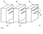
- Fig. 5 shows a further exemplary arrangement of three assumed as identical, identical construction single-phase winding modules 94, 96, 98 in a three-dimensional view.
- the single-phase winding modules essentially correspond to those in Fig.2 shown modules 52, 54, 56 and are arranged along a line at a distance which is marked with the reference numeral 102.
- connection devices of the first and third connection group are each pronounced as a plug-like survey and summarily designated by the reference numeral 100.
- the corresponding counterparts of the second and fourth terminal groups are socket-like pronounced, adapted form-fitting to the engraver-like elevations and each arranged along a line with the connection devices shown.
- the single-phase winding modules are to be pushed into one another by a displacement process along the distance indicated by the reference numeral 102, so that at their contiguous arrangement an electrical connection is given.
Landscapes
- Engineering & Computer Science (AREA)
- Power Engineering (AREA)
- Coils Of Transformers For General Uses (AREA)
Priority Applications (2)
| Application Number | Priority Date | Filing Date | Title |
|---|---|---|---|
| EP08020348A EP2189990B1 (fr) | 2008-11-22 | 2008-11-22 | Module d'enroulement à phase unique et arrangement de modules d'enroulement à phase unique |
| AT08020348T ATE534130T1 (de) | 2008-11-22 | 2008-11-22 | Einphasen-wicklungsmodul und anordnung von einphasen-wicklungsmodulen |
Applications Claiming Priority (1)
| Application Number | Priority Date | Filing Date | Title |
|---|---|---|---|
| EP08020348A EP2189990B1 (fr) | 2008-11-22 | 2008-11-22 | Module d'enroulement à phase unique et arrangement de modules d'enroulement à phase unique |
Publications (2)
| Publication Number | Publication Date |
|---|---|
| EP2189990A1 true EP2189990A1 (fr) | 2010-05-26 |
| EP2189990B1 EP2189990B1 (fr) | 2011-11-16 |
Family
ID=40524861
Family Applications (1)
| Application Number | Title | Priority Date | Filing Date |
|---|---|---|---|
| EP08020348A Not-in-force EP2189990B1 (fr) | 2008-11-22 | 2008-11-22 | Module d'enroulement à phase unique et arrangement de modules d'enroulement à phase unique |
Country Status (2)
| Country | Link |
|---|---|
| EP (1) | EP2189990B1 (fr) |
| AT (1) | ATE534130T1 (fr) |
Cited By (1)
| Publication number | Priority date | Publication date | Assignee | Title |
|---|---|---|---|---|
| US20200203066A1 (en) * | 2017-09-04 | 2020-06-25 | Siemens Aktiengesellschaft | Assembly for connection to a high-voltage system with adjustable impedance |
Citations (3)
| Publication number | Priority date | Publication date | Assignee | Title |
|---|---|---|---|---|
| DE1971623U (de) * | 1967-05-31 | 1967-11-02 | Licentia Gmbh | Schaltleiste fuer trocken- insbesondere giessharztransformatoren. |
| GB2337863A (en) | 1998-05-09 | 1999-12-01 | Frederick E Bott | Method and means of forming a desired coil configuration |
| EP1973126A1 (fr) * | 2007-03-20 | 2008-09-24 | Schneider Electric Industries Sas | Bobine de tension primaire ajustable pour transformateur sec et transformateur HT/BT la comprenant |
-
2008
- 2008-11-22 AT AT08020348T patent/ATE534130T1/de active
- 2008-11-22 EP EP08020348A patent/EP2189990B1/fr not_active Not-in-force
Patent Citations (3)
| Publication number | Priority date | Publication date | Assignee | Title |
|---|---|---|---|---|
| DE1971623U (de) * | 1967-05-31 | 1967-11-02 | Licentia Gmbh | Schaltleiste fuer trocken- insbesondere giessharztransformatoren. |
| GB2337863A (en) | 1998-05-09 | 1999-12-01 | Frederick E Bott | Method and means of forming a desired coil configuration |
| EP1973126A1 (fr) * | 2007-03-20 | 2008-09-24 | Schneider Electric Industries Sas | Bobine de tension primaire ajustable pour transformateur sec et transformateur HT/BT la comprenant |
Cited By (2)
| Publication number | Priority date | Publication date | Assignee | Title |
|---|---|---|---|---|
| US20200203066A1 (en) * | 2017-09-04 | 2020-06-25 | Siemens Aktiengesellschaft | Assembly for connection to a high-voltage system with adjustable impedance |
| US11594368B2 (en) * | 2017-09-04 | 2023-02-28 | Siemens Energy Global GmbH & Co. KG | Assembly for connection to a high-voltage system with adjustable impedance |
Also Published As
| Publication number | Publication date |
|---|---|
| EP2189990B1 (fr) | 2011-11-16 |
| ATE534130T1 (de) | 2011-12-15 |
Similar Documents
| Publication | Publication Date | Title |
|---|---|---|
| EP3567703B1 (fr) | Stator pour une machine électrique et procédé de fabrication | |
| DE102013101323B4 (de) | Filterbauelement | |
| DE112013006383B4 (de) | Drehende elektrische Maschine und Verfahren zum Herstellen eines Ankers, der in der drehenden elektrischen Maschine verwendet wird | |
| DE102017218108A1 (de) | Drahtverbindungsstruktur, Rauschunterdrückungseinheit und Kabelbaum | |
| DE102008050322B4 (de) | Elektromotor-Anschluss sowie Elektromotor | |
| WO2015063297A1 (fr) | Module pont pour rail profilé support | |
| EP1444761B1 (fr) | Systeme de barres collectrices polyphasees | |
| WO2008113397A1 (fr) | Élément de connexion pour la connexion de deux appareils de coupure | |
| WO2007023062A1 (fr) | Systeme de connexion comprenant un appareil de commutation electromagnetique, en particulier un contacteur electromagnetique, et un connecteur | |
| EP2277183B1 (fr) | Noyau toroïdal modulaire | |
| DE102018116447A1 (de) | Drossel mit einem an einer Anschlussbasiseinheit angebrachten Termperatursensor | |
| WO2018215547A1 (fr) | Tableau de distribution électrique | |
| DE102015115410A1 (de) | Induktive Strommesswandlervorrichtung | |
| EP3185365A1 (fr) | Rail d'alimentation | |
| EP2189990B1 (fr) | Module d'enroulement à phase unique et arrangement de modules d'enroulement à phase unique | |
| DE8115274U1 (de) | Vorrichtung zum Herstellen einer elektrischen Steckverbindung | |
| DE202007013483U1 (de) | Verbindungsklemmenblock für elektrische Mehrphasenmotoren | |
| DE202024101641U1 (de) | Hausstromunterverteiler | |
| DE102016202232A1 (de) | Elektrischer Stecker | |
| EP0975079A2 (fr) | Distributeur d'installation électrique | |
| EP3297108B1 (fr) | Structure à fusible destinée à la protection des conducteurs extérieurs d'un ensemble fusible électrique pour former un branchement de bâtiment | |
| EP2095382A1 (fr) | Transformateur avec enroulement de tôle de branchement | |
| DE3346381A1 (de) | Installationsverteilersystem | |
| WO2009138099A1 (fr) | Connexion de modules d'enroulements de transformateur | |
| DE102004052472B4 (de) | Sammelschienensystem für Schaltgeräte mit Modulen, die über Verbindungsstecker mit aufgesetzter Ausspeiseklemme elektrisch kontaktierbar sind |
Legal Events
| Date | Code | Title | Description |
|---|---|---|---|
| PUAI | Public reference made under article 153(3) epc to a published international application that has entered the european phase |
Free format text: ORIGINAL CODE: 0009012 |
|
| AK | Designated contracting states |
Kind code of ref document: A1 Designated state(s): AT BE BG CH CY CZ DE DK EE ES FI FR GB GR HR HU IE IS IT LI LT LU LV MC MT NL NO PL PT RO SE SI SK TR |
|
| AX | Request for extension of the european patent |
Extension state: AL BA MK RS |
|
| 17P | Request for examination filed |
Effective date: 20100511 |
|
| 17Q | First examination report despatched |
Effective date: 20100727 |
|
| AKX | Designation fees paid |
Designated state(s): AT BE BG CH CY CZ DE DK EE ES FI FR GB GR HR HU IE IS IT LI LT LU LV MC MT NL NO PL PT RO SE SI SK TR |
|
| GRAP | Despatch of communication of intention to grant a patent |
Free format text: ORIGINAL CODE: EPIDOSNIGR1 |
|
| GRAS | Grant fee paid |
Free format text: ORIGINAL CODE: EPIDOSNIGR3 |
|
| GRAA | (expected) grant |
Free format text: ORIGINAL CODE: 0009210 |
|
| AK | Designated contracting states |
Kind code of ref document: B1 Designated state(s): AT BE BG CH CY CZ DE DK EE ES FI FR GB GR HR HU IE IS IT LI LT LU LV MC MT NL NO PL PT RO SE SI SK TR |
|
| REG | Reference to a national code |
Ref country code: GB Ref legal event code: FG4D Free format text: NOT ENGLISH |
|
| REG | Reference to a national code |
Ref country code: CH Ref legal event code: EP |
|
| REG | Reference to a national code |
Ref country code: IE Ref legal event code: FG4D Free format text: LANGUAGE OF EP DOCUMENT: GERMAN |
|
| REG | Reference to a national code |
Ref country code: DE Ref legal event code: R096 Ref document number: 502008005580 Country of ref document: DE Effective date: 20120119 |
|
| REG | Reference to a national code |
Ref country code: NL Ref legal event code: VDEP Effective date: 20111116 |
|
| LTIE | Lt: invalidation of european patent or patent extension |
Effective date: 20111116 |
|
| PG25 | Lapsed in a contracting state [announced via postgrant information from national office to epo] |
Ref country code: IS Free format text: LAPSE BECAUSE OF FAILURE TO SUBMIT A TRANSLATION OF THE DESCRIPTION OR TO PAY THE FEE WITHIN THE PRESCRIBED TIME-LIMIT Effective date: 20120316 Ref country code: LT Free format text: LAPSE BECAUSE OF FAILURE TO SUBMIT A TRANSLATION OF THE DESCRIPTION OR TO PAY THE FEE WITHIN THE PRESCRIBED TIME-LIMIT Effective date: 20111116 Ref country code: NO Free format text: LAPSE BECAUSE OF FAILURE TO SUBMIT A TRANSLATION OF THE DESCRIPTION OR TO PAY THE FEE WITHIN THE PRESCRIBED TIME-LIMIT Effective date: 20120216 |
|
| BERE | Be: lapsed |
Owner name: ABB TECHNOLOGY A.G. Effective date: 20111130 |
|
| PG25 | Lapsed in a contracting state [announced via postgrant information from national office to epo] |
Ref country code: LV Free format text: LAPSE BECAUSE OF FAILURE TO SUBMIT A TRANSLATION OF THE DESCRIPTION OR TO PAY THE FEE WITHIN THE PRESCRIBED TIME-LIMIT Effective date: 20111116 Ref country code: PT Free format text: LAPSE BECAUSE OF FAILURE TO SUBMIT A TRANSLATION OF THE DESCRIPTION OR TO PAY THE FEE WITHIN THE PRESCRIBED TIME-LIMIT Effective date: 20120316 Ref country code: HR Free format text: LAPSE BECAUSE OF FAILURE TO SUBMIT A TRANSLATION OF THE DESCRIPTION OR TO PAY THE FEE WITHIN THE PRESCRIBED TIME-LIMIT Effective date: 20111116 Ref country code: SE Free format text: LAPSE BECAUSE OF FAILURE TO SUBMIT A TRANSLATION OF THE DESCRIPTION OR TO PAY THE FEE WITHIN THE PRESCRIBED TIME-LIMIT Effective date: 20111116 Ref country code: GR Free format text: LAPSE BECAUSE OF FAILURE TO SUBMIT A TRANSLATION OF THE DESCRIPTION OR TO PAY THE FEE WITHIN THE PRESCRIBED TIME-LIMIT Effective date: 20120217 Ref country code: NL Free format text: LAPSE BECAUSE OF FAILURE TO SUBMIT A TRANSLATION OF THE DESCRIPTION OR TO PAY THE FEE WITHIN THE PRESCRIBED TIME-LIMIT Effective date: 20111116 Ref country code: PL Free format text: LAPSE BECAUSE OF FAILURE TO SUBMIT A TRANSLATION OF THE DESCRIPTION OR TO PAY THE FEE WITHIN THE PRESCRIBED TIME-LIMIT Effective date: 20111116 Ref country code: SI Free format text: LAPSE BECAUSE OF FAILURE TO SUBMIT A TRANSLATION OF THE DESCRIPTION OR TO PAY THE FEE WITHIN THE PRESCRIBED TIME-LIMIT Effective date: 20111116 |
|
| REG | Reference to a national code |
Ref country code: IE Ref legal event code: FD4D |
|
| PG25 | Lapsed in a contracting state [announced via postgrant information from national office to epo] |
Ref country code: CY Free format text: LAPSE BECAUSE OF FAILURE TO SUBMIT A TRANSLATION OF THE DESCRIPTION OR TO PAY THE FEE WITHIN THE PRESCRIBED TIME-LIMIT Effective date: 20111116 Ref country code: MC Free format text: LAPSE BECAUSE OF NON-PAYMENT OF DUE FEES Effective date: 20111130 |
|
| PG25 | Lapsed in a contracting state [announced via postgrant information from national office to epo] |
Ref country code: BG Free format text: LAPSE BECAUSE OF FAILURE TO SUBMIT A TRANSLATION OF THE DESCRIPTION OR TO PAY THE FEE WITHIN THE PRESCRIBED TIME-LIMIT Effective date: 20120216 Ref country code: IE Free format text: LAPSE BECAUSE OF FAILURE TO SUBMIT A TRANSLATION OF THE DESCRIPTION OR TO PAY THE FEE WITHIN THE PRESCRIBED TIME-LIMIT Effective date: 20111116 Ref country code: DK Free format text: LAPSE BECAUSE OF FAILURE TO SUBMIT A TRANSLATION OF THE DESCRIPTION OR TO PAY THE FEE WITHIN THE PRESCRIBED TIME-LIMIT Effective date: 20111116 Ref country code: SK Free format text: LAPSE BECAUSE OF FAILURE TO SUBMIT A TRANSLATION OF THE DESCRIPTION OR TO PAY THE FEE WITHIN THE PRESCRIBED TIME-LIMIT Effective date: 20111116 Ref country code: EE Free format text: LAPSE BECAUSE OF FAILURE TO SUBMIT A TRANSLATION OF THE DESCRIPTION OR TO PAY THE FEE WITHIN THE PRESCRIBED TIME-LIMIT Effective date: 20111116 Ref country code: CZ Free format text: LAPSE BECAUSE OF FAILURE TO SUBMIT A TRANSLATION OF THE DESCRIPTION OR TO PAY THE FEE WITHIN THE PRESCRIBED TIME-LIMIT Effective date: 20111116 |
|
| PG25 | Lapsed in a contracting state [announced via postgrant information from national office to epo] |
Ref country code: BE Free format text: LAPSE BECAUSE OF NON-PAYMENT OF DUE FEES Effective date: 20111130 Ref country code: IT Free format text: LAPSE BECAUSE OF FAILURE TO SUBMIT A TRANSLATION OF THE DESCRIPTION OR TO PAY THE FEE WITHIN THE PRESCRIBED TIME-LIMIT Effective date: 20111116 Ref country code: RO Free format text: LAPSE BECAUSE OF FAILURE TO SUBMIT A TRANSLATION OF THE DESCRIPTION OR TO PAY THE FEE WITHIN THE PRESCRIBED TIME-LIMIT Effective date: 20111116 |
|
| PLBE | No opposition filed within time limit |
Free format text: ORIGINAL CODE: 0009261 |
|
| STAA | Information on the status of an ep patent application or granted ep patent |
Free format text: STATUS: NO OPPOSITION FILED WITHIN TIME LIMIT |
|
| 26N | No opposition filed |
Effective date: 20120817 |
|
| REG | Reference to a national code |
Ref country code: FR Ref legal event code: ST Effective date: 20121019 |
|
| REG | Reference to a national code |
Ref country code: DE Ref legal event code: R097 Ref document number: 502008005580 Country of ref document: DE Effective date: 20120817 |
|
| PG25 | Lapsed in a contracting state [announced via postgrant information from national office to epo] |
Ref country code: FR Free format text: LAPSE BECAUSE OF NON-PAYMENT OF DUE FEES Effective date: 20120116 |
|
| PG25 | Lapsed in a contracting state [announced via postgrant information from national office to epo] |
Ref country code: MT Free format text: LAPSE BECAUSE OF FAILURE TO SUBMIT A TRANSLATION OF THE DESCRIPTION OR TO PAY THE FEE WITHIN THE PRESCRIBED TIME-LIMIT Effective date: 20111116 |
|
| PG25 | Lapsed in a contracting state [announced via postgrant information from national office to epo] |
Ref country code: ES Free format text: LAPSE BECAUSE OF FAILURE TO SUBMIT A TRANSLATION OF THE DESCRIPTION OR TO PAY THE FEE WITHIN THE PRESCRIBED TIME-LIMIT Effective date: 20120227 |
|
| PG25 | Lapsed in a contracting state [announced via postgrant information from national office to epo] |
Ref country code: LU Free format text: LAPSE BECAUSE OF NON-PAYMENT OF DUE FEES Effective date: 20111122 |
|
| PG25 | Lapsed in a contracting state [announced via postgrant information from national office to epo] |
Ref country code: FI Free format text: LAPSE BECAUSE OF FAILURE TO SUBMIT A TRANSLATION OF THE DESCRIPTION OR TO PAY THE FEE WITHIN THE PRESCRIBED TIME-LIMIT Effective date: 20111116 |
|
| REG | Reference to a national code |
Ref country code: CH Ref legal event code: PL |
|
| GBPC | Gb: european patent ceased through non-payment of renewal fee |
Effective date: 20121122 |
|
| PG25 | Lapsed in a contracting state [announced via postgrant information from national office to epo] |
Ref country code: LI Free format text: LAPSE BECAUSE OF NON-PAYMENT OF DUE FEES Effective date: 20121130 Ref country code: CH Free format text: LAPSE BECAUSE OF NON-PAYMENT OF DUE FEES Effective date: 20121130 |
|
| PG25 | Lapsed in a contracting state [announced via postgrant information from national office to epo] |
Ref country code: TR Free format text: LAPSE BECAUSE OF FAILURE TO SUBMIT A TRANSLATION OF THE DESCRIPTION OR TO PAY THE FEE WITHIN THE PRESCRIBED TIME-LIMIT Effective date: 20111116 |
|
| PG25 | Lapsed in a contracting state [announced via postgrant information from national office to epo] |
Ref country code: HU Free format text: LAPSE BECAUSE OF FAILURE TO SUBMIT A TRANSLATION OF THE DESCRIPTION OR TO PAY THE FEE WITHIN THE PRESCRIBED TIME-LIMIT Effective date: 20111116 |
|
| PG25 | Lapsed in a contracting state [announced via postgrant information from national office to epo] |
Ref country code: GB Free format text: LAPSE BECAUSE OF NON-PAYMENT OF DUE FEES Effective date: 20121122 |
|
| PGFP | Annual fee paid to national office [announced via postgrant information from national office to epo] |
Ref country code: DE Payment date: 20131121 Year of fee payment: 6 |
|
| REG | Reference to a national code |
Ref country code: AT Ref legal event code: MM01 Ref document number: 534130 Country of ref document: AT Kind code of ref document: T Effective date: 20131122 |
|
| PG25 | Lapsed in a contracting state [announced via postgrant information from national office to epo] |
Ref country code: AT Free format text: LAPSE BECAUSE OF NON-PAYMENT OF DUE FEES Effective date: 20131122 |
|
| REG | Reference to a national code |
Ref country code: DE Ref legal event code: R119 Ref document number: 502008005580 Country of ref document: DE |
|
| PG25 | Lapsed in a contracting state [announced via postgrant information from national office to epo] |
Ref country code: DE Free format text: LAPSE BECAUSE OF NON-PAYMENT OF DUE FEES Effective date: 20150602 |