EP2190068A1 - Connecteur doté d'un arrêt positif pour câble coaxial et procédés apparentés - Google Patents
Connecteur doté d'un arrêt positif pour câble coaxial et procédés apparentés Download PDFInfo
- Publication number
- EP2190068A1 EP2190068A1 EP09176852A EP09176852A EP2190068A1 EP 2190068 A1 EP2190068 A1 EP 2190068A1 EP 09176852 A EP09176852 A EP 09176852A EP 09176852 A EP09176852 A EP 09176852A EP 2190068 A1 EP2190068 A1 EP 2190068A1
- Authority
- EP
- European Patent Office
- Prior art keywords
- connector
- back nut
- outer conductor
- connector housing
- coaxial cable
- Prior art date
- Legal status (The legal status is an assumption and is not a legal conclusion. Google has not performed a legal analysis and makes no representation as to the accuracy of the status listed.)
- Ceased
Links
- 238000000034 method Methods 0.000 title claims description 20
- 239000004020 conductor Substances 0.000 claims abstract description 108
- 239000012212 insulator Substances 0.000 claims abstract description 29
- 238000007789 sealing Methods 0.000 claims description 23
- 238000004519 manufacturing process Methods 0.000 claims description 2
- 238000009434 installation Methods 0.000 description 4
- XAGFODPZIPBFFR-UHFFFAOYSA-N aluminium Chemical compound [Al] XAGFODPZIPBFFR-UHFFFAOYSA-N 0.000 description 2
- 229910052782 aluminium Inorganic materials 0.000 description 2
- 230000008901 benefit Effects 0.000 description 2
- 230000006835 compression Effects 0.000 description 2
- 238000007906 compression Methods 0.000 description 2
- 238000012986 modification Methods 0.000 description 2
- 230000004048 modification Effects 0.000 description 2
- 230000001413 cellular effect Effects 0.000 description 1
- 238000010276 construction Methods 0.000 description 1
- 230000003247 decreasing effect Effects 0.000 description 1
- 238000005516 engineering process Methods 0.000 description 1
- 239000006260 foam Substances 0.000 description 1
- 238000009413 insulation Methods 0.000 description 1
- 230000013011 mating Effects 0.000 description 1
- 238000010008 shearing Methods 0.000 description 1
Images



Classifications
-
- H—ELECTRICITY
- H01—ELECTRIC ELEMENTS
- H01R—ELECTRICALLY-CONDUCTIVE CONNECTIONS; STRUCTURAL ASSOCIATIONS OF A PLURALITY OF MUTUALLY-INSULATED ELECTRICAL CONNECTING ELEMENTS; COUPLING DEVICES; CURRENT COLLECTORS
- H01R9/00—Structural associations of a plurality of mutually-insulated electrical connecting elements, e.g. terminal strips or terminal blocks; Terminals or binding posts mounted upon a base or in a case; Bases therefor
- H01R9/03—Connectors arranged to contact a plurality of the conductors of a multiconductor cable, e.g. tapping connections
- H01R9/05—Connectors arranged to contact a plurality of the conductors of a multiconductor cable, e.g. tapping connections for coaxial cables
- H01R9/0521—Connection to outer conductor by action of a nut
-
- H—ELECTRICITY
- H01—ELECTRIC ELEMENTS
- H01R—ELECTRICALLY-CONDUCTIVE CONNECTIONS; STRUCTURAL ASSOCIATIONS OF A PLURALITY OF MUTUALLY-INSULATED ELECTRICAL CONNECTING ELEMENTS; COUPLING DEVICES; CURRENT COLLECTORS
- H01R13/00—Details of coupling devices of the kinds covered by groups H01R12/70 or H01R24/00 - H01R33/00
- H01R13/46—Bases; Cases
- H01R13/52—Dustproof, splashproof, drip-proof, waterproof, or flameproof cases
- H01R13/5202—Sealing means between parts of housing or between housing part and a wall, e.g. sealing rings
-
- H—ELECTRICITY
- H01—ELECTRIC ELEMENTS
- H01R—ELECTRICALLY-CONDUCTIVE CONNECTIONS; STRUCTURAL ASSOCIATIONS OF A PLURALITY OF MUTUALLY-INSULATED ELECTRICAL CONNECTING ELEMENTS; COUPLING DEVICES; CURRENT COLLECTORS
- H01R24/00—Two-part coupling devices, or either of their cooperating parts, characterised by their overall structure
- H01R24/38—Two-part coupling devices, or either of their cooperating parts, characterised by their overall structure having concentrically or coaxially arranged contacts
- H01R24/40—Two-part coupling devices, or either of their cooperating parts, characterised by their overall structure having concentrically or coaxially arranged contacts specially adapted for high frequency
-
- H—ELECTRICITY
- H01—ELECTRIC ELEMENTS
- H01R—ELECTRICALLY-CONDUCTIVE CONNECTIONS; STRUCTURAL ASSOCIATIONS OF A PLURALITY OF MUTUALLY-INSULATED ELECTRICAL CONNECTING ELEMENTS; COUPLING DEVICES; CURRENT COLLECTORS
- H01R9/00—Structural associations of a plurality of mutually-insulated electrical connecting elements, e.g. terminal strips or terminal blocks; Terminals or binding posts mounted upon a base or in a case; Bases therefor
- H01R9/03—Connectors arranged to contact a plurality of the conductors of a multiconductor cable, e.g. tapping connections
- H01R9/05—Connectors arranged to contact a plurality of the conductors of a multiconductor cable, e.g. tapping connections for coaxial cables
- H01R9/0527—Connection to outer conductor by action of a resilient member, e.g. spring
-
- H—ELECTRICITY
- H01—ELECTRIC ELEMENTS
- H01R—ELECTRICALLY-CONDUCTIVE CONNECTIONS; STRUCTURAL ASSOCIATIONS OF A PLURALITY OF MUTUALLY-INSULATED ELECTRICAL CONNECTING ELEMENTS; COUPLING DEVICES; CURRENT COLLECTORS
- H01R2103/00—Two poles
-
- H—ELECTRICITY
- H01—ELECTRIC ELEMENTS
- H01R—ELECTRICALLY-CONDUCTIVE CONNECTIONS; STRUCTURAL ASSOCIATIONS OF A PLURALITY OF MUTUALLY-INSULATED ELECTRICAL CONNECTING ELEMENTS; COUPLING DEVICES; CURRENT COLLECTORS
- H01R24/00—Two-part coupling devices, or either of their cooperating parts, characterised by their overall structure
- H01R24/38—Two-part coupling devices, or either of their cooperating parts, characterised by their overall structure having concentrically or coaxially arranged contacts
- H01R24/40—Two-part coupling devices, or either of their cooperating parts, characterised by their overall structure having concentrically or coaxially arranged contacts specially adapted for high frequency
- H01R24/56—Two-part coupling devices, or either of their cooperating parts, characterised by their overall structure having concentrically or coaxially arranged contacts specially adapted for high frequency specially adapted to a specific shape of cables, e.g. corrugated cables, twisted pair cables, cables with two screens or hollow cables
Definitions
- the present invention relates to the field of connectors for cables, and, more particularly, to connectors for coaxial cables and related methods,
- Coaxial cables are widely used to carry high frequency electrical signals. Coaxial cables enjoy a relatively high bandwidth, low signal losses, are mechanically robust, and are relatively low cost.
- One particularly advantageous use of a coaxial cable is for connecting electronics at a cellular or wireless base station to an antenna mounted at the top of a nearby antenna tower.
- the transmitter located in an equipment shelter may be connected to a transmit antenna supported by the antenna tower.
- the receiver is also connected to its associated receiver antenna by a coaxial cable path.
- a typical installation includes a relatively large diameter coaxial cable extending between the equipment shelter and the top of the antenna tower to thereby reduce signal losses.
- Some coaxial cables include a smooth outer conductor while other coaxial cables instead have a corrugated outer conductor.
- These coaxial cables also have an inner conductor and a dielectric between the outer conductor and the inner conductor.
- Some inner conductors are hollow, while other inner conductors are formed around an inner conductor dielectric core.
- a typical connector for such a coaxial cable includes a connector housing to make an electrical connection to the outer conductor and a center contact to make electrical connection to the inner conductor of the coaxial cable, Such a connector may also include a back nut that is positioned onto the end of the outer conductor and adjacent the outer insulating jacket portion of the coaxial cable.
- U.S. Pat. No. 5,795,188 to Harwath discloses a connector for a coaxial cable having a corrugated outer conductor.
- the connector includes a connector housing defining a radially outer ramp to contact the inside surface of a flared end portion of an outer conductor of the coaxial cable
- a clamping ring is in the corrugation adjacent to the flared end portion of the outer conductor. The clamping ring presses the outer surface of the outer conductor against the radially outer ramp to provide electrical contact therebetween.
- U.S. Pat, No. 7,011,546 to Vaccaro discloses a connector for a coaxial cable having a smooth outer conductor.
- the connector includes a connector housing, a back nut threadingly engaging a rearward end of the connector housing, a ferrule gripping and advancing an end of the coaxial cable into the connector housing as the back nut is tightened, and an insulator member positioned within a medial portion of the connector housing.
- the insulator member has a bore extending therethrough and includes a forward disk portion, a rearward disk portion, a ring portion connecting the forward and disk portions together, and a tubular outer conductor support portion extending rearwardly from the rearward disk portion for supporting an interior surface of the outer conductor of the coaxial cable.
- U.S. Pat. No. 7,077,700 to Henningsen discloses a coaxial cable connector including a removable back nut, an outer body, and a center conductor supported within the outer body by a dielectric.
- An uncompressible clamp ring is rotatably disposed within the central bore of the back nut.
- a prepared end of a coaxial cable is inserted through the back nut, and the end portion of the outer conductor of' the coaxial cable is flared outwardly. As the back nut is tightened onto the outer body, the flared end of the outer conductor is clamped between mating clamping surfaces formed on the clamp ring and the outer body.
- a connector to be attached to a coaxial cable comprising an inner conductor, an outer conductor, and a dielectric therebetween.
- the outer conductor may be a smooth wall outer conductor or, alternatively, may be a corrugated outer conductor.
- the connector may comprise a connector housing defining a ramp to receive the outer conductor thereagainst and a back nut. A portion of the connector housing and the back nut may include respective portions defining a positive stop when fully engaged. The positive stop may allow the connector to be attached to the coaxial cable without a torque wrench or other torque limiting tool, as the positive stop indicates to the installer when to stop tightening the back nut and the connector housing together.
- the connector may further comprise an electrically conductive compressible coil spring to compressibly clamp against the outer conductor opposite the ramp when the connector housing and back nut are engaged.
- This advantageously provides secure mechanical and electrical connections between the outer conductor and the connector housing. Furthermore, this maintains a sufficient clamping force on the outer conductor opposite the radially outer ramp during vibration of the connector or if the size and/or shape of the outer conductor changes due to thermal expansion or aluminum creep.
- the electrically conductive compressible coil spring may have an axis coaxial with the connector housing.
- the connector housing may comprise a rearward portion threadingly received with a forward portion of' the back nut.
- the connector may also include a center contact to be coupled to the inner conductor.
- An insulator member may be in the connector housing for carrying the center contact.
- the connector housing may comprise an enlarged diameter tool engaging portion.
- the back nut may comprise a forward portion and the positive stop may defined by the enlarged diameter tool engaging portion and the forward portion of the back nut.
- at least one sealing ring may be positioned radially inward of and adjacent to the positive stop.
- the back nut may have a spring cavity defined therein.
- the electrically conductive compressible coil spring may be positioned in the spring cavity.
- the insulator member may comprise a radially outer support portion to radially support the outer conductor opposite the compressible ring. This radial support portion supports the outer conductor radially outwardly as the electrically conductive compressible coil spring urges the outer conductor radially inwardly.
- the ramp may have a stair-stepped shape.
- This stair-stepped shape may present an increased friction surface to the outer conductor to help prevent unwanted movement of the outer conductor, This stair-stepped shape may also enhance the electrical contact with the outer conductor.
- the insulator member may have a central opening defined therein to carry the inner conductor. Also, there may be an additional insulator member spaced apart from, and positioned rearwardly of, the insulator member in the connector housing that has a central opening defined therein to carry the center contact.
- the back nut may have a plurality of threads to threadingly receive the coaxial cable. Each of the plurality of threads may have a chamfered end and respective ones of the chamfered ends may be spaced apart from each other.
- At least one sealing ring may be carried within the back nut. This sealing ring may seal the interior of the connector housing and the back nut from moisture and debris.
- the back nut may have a sealing ring cavity formed therein.
- the at least one sealing ring may be positioned within the sealing ring cavity so that the coaxial cable compresses the at least one sealing ring when the back nut is attached to the coaxial cable.
- the at least one sealing ring may comprise a radially inwardly extending forward end to seal against an exposed portion of the outer conductor of the coaxial cable. Additionally or alternatively, the at least one sealing ring comprises a radially inwardly extending forward end to seal against an exposed portion of a jacket of the outer conductor.
- the outer conductor of the coaxial cable may comprise a corrugated outer conductor or a smooth outer conductor.
- the connector may accommodate either corrugated and smooth outer conductors. This advantageously allows a same connector to be used for multiple cable types.
- a method aspect is directed to a method of' making connector to be attached to a coaxial cable comprising an inner conductor, an outer conductor, and a dielectric therebetween.
- the method may comprise forming a connector housing having a ramp to receive the outer conductor thereagainst. Furthermore, the method may include forming a back nut have a forward portion to threadingly receive a rearward portion of the connector housing and to define a positive stop therewith when fully engaged with the connector housing.
- An electrically conductive compressible coil spring may be formed to be compressibly clamped against the outer conductor opposite the ramp when the connector housing and a back nut are engaged. Furthermore, the method may include forming an insulator member to be positioned in the connector housing for carrying a center contact to be coupled to the inner conductor.
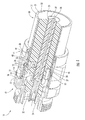
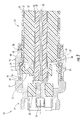
- the coaxial cable 30 comprises an inner conductor 33, an outer conductor 31, and a dielectric 32 therebetween.
- the inner conductor 33 is illustratively a tubular inner conductor with a dielectric core.
- the outer conductor 31 is illustratively a corrugated outer conductor with a flared end 35, but could be a smooth outer conductor in other embodiments.
- the dielectric 32 may be a foam dielectric or other dielectric as known to those skilled in the art.
- the connector 10 includes an internally threaded back nut 12 to receive an externally threaded rearward end of a connector housing 12,
- a forward o-ring 19 and a rearward o-ring 20 are illustratively provided to seal respective forward and rearward interfaces adjacent the back nut 14 and may prevent moisture ingress.
- the o-rings 19, 20 may be gaskets instead of o-rings, as will be appreciated by one of skill in the art.
- a sealing ring 40 is positioned between the o-rings 19, 20. The sealing ring further helps in sealing both the jacket 34 and the outer conductor 31.
- the back nut 14 has a sealing ring pocket defined 43 therein.
- the sealing ring 40 is positioned in the sealing ring cavity 43 so that the coaxial cable 30 compresses the sealing ring both longitudinally and radially when the back nut 14 is installed on the coaxial cable.
- the sealing ring 40 as shown in the exploded view of FIG. 3 , is uncompressed because the back nut 14 is not attached to the coaxial cable 30.
- the sealing ring 40 is compressed.
- the connector housing 12 defines a ramp 13 to receive the outer conductor 31 thereagainst.
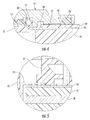
- the ramp 13 illustratively has a stair-stepped surface, although the skilled artisan will understand that other ramp surfaces may be used. ( FIG. 4 )
- the ramp 13 may have a radiused concave shape.
- the end of the coaxial cable 30 is prepared so that the inner conductor 33 extends longitudinally outwardly beyond the end of' the outer conductor 31.
- portions of' the dielectric 32 are removed in a stair-stepped fashion so that the inner surface of the outer conductor 31 is also exposed.
- the coaxial cable 30 illustratively includes an outer insulation jacket 34 stripped back a distance so that outer end portions of the outer conductor 31 are exposed.
- the outer conductor 31 is flared outwardly to define the flared end 35.
- a portion of the connector housing 12 and a portion of the back nut 14 include respective portions defining a positive stop 18 when fully engaged. More particularly, the connector housing 12 comprises an enlarged diameter tool engaging portion 17 and the back nut 14 comprises a forward end 16.
- the positive stop 18 is defined by the abutting relationship between enlarged diameter tool engaging portion 17 and the forward end 16 of the back nut.
- the forward o-ring 19 is radially inward of and adjacent to the positive stop 18. The seal formed by the forward o-ring 19 is activated by threading the back nut 14 onto the jacket 34. The forward o-ring reduces the gap between the jacket 34 and the forward end 16 of the back nut.
- the connector housing 12 may have a rear portion to engage with a shoulder of the back nut 14 to define the positive stop 18.
- the positive stop 18 helps prevent overtightening of the engagement between the connector housing 12 and the back nut 14 that may generate compression and or shearing forces at potentially damaging levels.
- the positive stop 18 therefore facilitates easy installation of the connector 10 on the coaxial cable 30 by eliminating the need for a torque wrench or other torque limiting tool.
- the back nut 14 illustratively has a spring cavity 26 to receive an electrically conductive compressible coil spring 15 therein.
- the electrically conductive compressible coil spring 15 compressibly clamps against the outer conductor 31 opposite the ramp 13 as the connector housing 12 and back nut 14 are engaged.
- the electrically conductive compressible coil spring 15 illustratively has an axis coaxial with that of the connector housing 12.
- the electrically conductive compressible coil spring 15 may be a coil spring, garter spring, or stamped ring.
- This clamping helps to provide an electrical connection between the outer conductor 31 and the ramp 13 by providing a constant contact pressure between the outer conductor and the ramp. By maintaining such a secure electrical connection, the intermodulation distortion of signals traveling through the coaxial cable 30 may be reduce.
- the electrically conductive compressible coil spring 15 advantageously maintains a sufficient clamping force on the outer conductor 31 even if the outer conductor changes shape or size due to thermal expansion or aluminum creep, for example, whereas an arrangement of two wedging surfaces to clamp the outer conductor might lose clamping force and contact pressure if the outer conductor were to change shape or size. Furthermore, by maintaining a constant clamping force on the outer conductor 31, the electrically conductive compressible coil spring 15 allows the connector 10 to be used with both smooth wall outer conductor coaxial cables 30 corrugated outer conductor coaxial cables. In addition the electrically conductive compressible coil spring 15 allows the connector 10 to be used on a variety of coaxial cables with different thicknesses, and on a variety of coaxial cables with outer conductors having different thicknesses.
- the insulator member 21 comprises a radially outer support portion 22 to radially support the outer conductor 31 opposite the electrically conductive compressible coil spring 15. This radial support supports the outer conductor 31 radially outwardly as the electrically conductive compressible coil spring 15 urges the outer conductor radially inwardly. Furthermore, the radially outer support portion 22 helps to reduce the chance of a loss of' electrical contact between the outer conductor 31 and the ramp 13 due to flexing of the coaxial cable 30 or due to compression of the dielectric 32. It should be noted that the insulator member 21. may have a rigid structure.
- a center contact 24 is supported in the connector housing 12 by an additional insulator member 23 and is electrically connected to the inner conductor 33.
- the insulator member 21 is also carries the inner conductor 33 of the cable to reduce or prevent movement to thereby reduce IMD ( FIG. 5 ).
- the clamping provided by the electrically conductive compressible coil spring 15 reduces radial movement of the connector 10 about the coaxial cable 30, That is, the electrically conductive compressible coil spring 15 acts as an antirotational device, such as a lock washer, to clamp the coaxial cable 30 between the connector housing 12 and back nut 14 and bite into the outer conductor 31 to reduce or prevent rotation of the connector 10 about the coaxial cable 30.
- the insulator member 21 illustratively includes a rearward portion 27 engaging the dielectric 32 of the coaxial cable 30.
- the illustrated insulator member 21 and additional insulator member 23 are each single monolithic units. This monolithic construction helps to reduce the number of connector components and thereby reduce the overall cost of the connector 10.
- the insulator member 21 and additional insulator member 23 may also be two-piece units in some applications.
- the back nut 14 has a plurality of (for example, three) starting threads 41 to threadingly receive the coaxial cable 30.
- These starting threads 41 assist a technician with threading the back nut 14 onto the coaxial cable 30 properly and evenly by aligning the longitudinal axis of the back nut with the longitudinal axis of the coaxial cable by balancing the back nut with a plurality of threads points on the jacket 34.
- IMD intermodulation distortion
- the starting threads 41 may reduce installation time by allowing the back nut 14 to be threaded into the coaxial cable 30 with a decreased amount of rotations as opposed to a back nut without the starting threads.
- each of the starting threads 41 has a chamfered end These chamfered ends are spaced apart from each other.
- the starting threads 41 need not have such chamfered ends in all embodiments.
- the connector 10' is installed on a coaxial cable having a corrugated outer conductor 31.
- the back nut 14" lacks a rearward o-ring. Instead, the sealing ring 40" seals both the jacket 34" and the outer conductor 31". As explained above, the sealing ring 40" resides in a sealing ring pocket 43" defined in the back nut 14" and is compressed radially and longitudinally outwardly when the back nut is installed on the coaxial cable 30".
- Those other elements not specifically mentioned are indicated with prime notation and are similar to the elements described above with reference to FIG. 1 . Accordingly, those other elements require no further description herein.
- a method aspect is directed to a method of making connector 10 to be attached to a coaxial cable 30 comprising an inner conductor 33, an outer conductor 31, and a dielectric 32 therebetween.
- the method comprises forming a connector housing 12 having a ramp 13 to receive the outer conductor 31 thereagainst. Furthermore, the method includes forming a back nut 14 having a forward portion 16 to threadingly receive a rearward portion 36 of the connector housing and to define a positive stop 18 therewith.
- the method includes forming an electrically conductive compressible coil spring 15 to be compressibly clamped against the outer conductor 31 opposite the ramp 13 when the connector housing 12 and a back nut 12 are engaged.
- An insulator member 21 is formed to be positioned in the connector housing 12 for carrying a center contact 24 to be coupled to the inner conductor 33.
- the insulator member 21 is also for carrying the inner conductor 33 of the cable to reduce or prevent movement thereby to reduce IMD.
- connectors 10 for coaxial cables 30 may be found in co-pending applications CONNECTOR INCLUDING COMPRESSIBLE RING FOR COAXIAL CABLE AND ASSOCIATED METHODS, Attorney Docket No. 63260, FLARING COAXIAL CABLE END PREPARATION TOOL AND ASSOCIATED METHODS, Attorney Docket No. 63261, CONNECTOR WITH POSITIVE STOP AND COMPRESSIBLE RING FOR COAXIAL CABLE AND ASSOCIATED METHODS, Attorney Docket No. 63265 and CONNECTOR WITH RETAINING RING FOR COAXIAL CABLE AND ASSOCIATED METHODS, Attorney Docket No. 63266, the entire disclosures of which are hereby incorporated by reference.
Landscapes
- Coupling Device And Connection With Printed Circuit (AREA)
Applications Claiming Priority (1)
| Application Number | Priority Date | Filing Date | Title |
|---|---|---|---|
| US12/277,103 US7785144B1 (en) | 2008-11-24 | 2008-11-24 | Connector with positive stop for coaxial cable and associated methods |
Publications (1)
| Publication Number | Publication Date |
|---|---|
| EP2190068A1 true EP2190068A1 (fr) | 2010-05-26 |
Family
ID=41651429
Family Applications (1)
| Application Number | Title | Priority Date | Filing Date |
|---|---|---|---|
| EP09176852A Ceased EP2190068A1 (fr) | 2008-11-24 | 2009-11-24 | Connecteur doté d'un arrêt positif pour câble coaxial et procédés apparentés |
Country Status (3)
| Country | Link |
|---|---|
| US (1) | US7785144B1 (fr) |
| EP (1) | EP2190068A1 (fr) |
| CN (1) | CN101820109B (fr) |
Cited By (12)
| Publication number | Priority date | Publication date | Assignee | Title |
|---|---|---|---|---|
| WO2012048260A1 (fr) * | 2010-10-08 | 2012-04-12 | John Mezzalingua Associates, Inc. | Ensemble connecteur pour câble coaxial ondulé |
| US8298006B2 (en) | 2010-10-08 | 2012-10-30 | John Mezzalingua Associates, Inc. | Connector contact for tubular center conductor |
| US8430688B2 (en) | 2010-10-08 | 2013-04-30 | John Mezzalingua Associates, LLC | Connector assembly having deformable clamping surface |
| US8435073B2 (en) | 2010-10-08 | 2013-05-07 | John Mezzalingua Associates, LLC | Connector assembly for corrugated coaxial cable |
| US8439703B2 (en) | 2010-10-08 | 2013-05-14 | John Mezzalingua Associates, LLC | Connector assembly for corrugated coaxial cable |
| US8449325B2 (en) | 2010-10-08 | 2013-05-28 | John Mezzalingua Associates, LLC | Connector assembly for corrugated coaxial cable |
| US8458898B2 (en) | 2010-10-28 | 2013-06-11 | John Mezzalingua Associates, LLC | Method of preparing a terminal end of a corrugated coaxial cable for termination |
| US8628352B2 (en) | 2011-07-07 | 2014-01-14 | John Mezzalingua Associates, LLC | Coaxial cable connector assembly |
| US9017102B2 (en) | 2012-02-06 | 2015-04-28 | John Mezzalingua Associates, LLC | Port assembly connector for engaging a coaxial cable and an outer conductor |
| US9083113B2 (en) | 2012-01-11 | 2015-07-14 | John Mezzalingua Associates, LLC | Compression connector for clamping/seizing a coaxial cable and an outer conductor |
| US9099825B2 (en) | 2012-01-12 | 2015-08-04 | John Mezzalingua Associates, LLC | Center conductor engagement mechanism |
| US9172156B2 (en) | 2010-10-08 | 2015-10-27 | John Mezzalingua Associates, LLC | Connector assembly having deformable surface |
Families Citing this family (22)
| Publication number | Priority date | Publication date | Assignee | Title |
|---|---|---|---|---|
| US8136234B2 (en) * | 2008-11-24 | 2012-03-20 | Andrew Llc | Flaring coaxial cable end preparation tool and associated methods |
| US7931499B2 (en) * | 2009-01-28 | 2011-04-26 | Andrew Llc | Connector including flexible fingers and associated methods |
| US7950957B1 (en) * | 2009-12-23 | 2011-05-31 | BNS Precision Industry Co., Ltd. | Coaxial connector with a compression ring between a sleeve and a sheath of the coaxial cable |
| US8579658B2 (en) * | 2010-08-20 | 2013-11-12 | Timothy L. Youtsey | Coaxial cable connectors with washers for preventing separation of mated connectors |
| US8303338B2 (en) * | 2011-03-25 | 2012-11-06 | Ezconn Corporation | Grounding electrical connector |
| US20120295464A1 (en) | 2011-05-19 | 2012-11-22 | Pct International, Inc. | Coaxial connector |
| DE102011106736B4 (de) * | 2011-06-28 | 2013-01-31 | Ims Connector Systems Gmbh | Gehäusestecker und Gehäusebuchse sowie Werkzeug dafür |
| US9028276B2 (en) | 2011-12-06 | 2015-05-12 | Pct International, Inc. | Coaxial cable continuity device |
| US8939785B2 (en) * | 2012-10-04 | 2015-01-27 | Gt Contact Co., Ltd. | Cable connector with spring-loaded plunger and assembly thereof |
| CN105518946A (zh) * | 2013-06-17 | 2016-04-20 | 科姆斯科普科技有限公司 | 关于电容联接的同轴线缆及连接器 |
| WO2015120576A1 (fr) * | 2014-02-11 | 2015-08-20 | Commscope Technologies Llc | Câble et connecteur coaxiaux à espaceur diélectrique empêchant un écoulement de brasure indésirable |
| PT3155693T (pt) * | 2014-06-16 | 2021-03-11 | Omega Flex Inc | Encaixe para uso com cabo blindado |
| US9450338B2 (en) * | 2014-08-06 | 2016-09-20 | Molex, Llc | High speed connector with ruggedized exterior structure and shielding |
| CN105470672A (zh) * | 2015-12-30 | 2016-04-06 | 南京双京电器集团有限公司 | 电缆连接器 |
| CN108011264B (zh) | 2016-10-31 | 2021-08-13 | 康普技术有限责任公司 | 快速锁定同轴连接器和连接器组合 |
| US10439302B2 (en) | 2017-06-08 | 2019-10-08 | Pct International, Inc. | Connecting device for connecting and grounding coaxial cable connectors |
| CN109256645B (zh) | 2017-07-12 | 2021-09-21 | 康普技术有限责任公司 | 快速锁定同轴连接器 |
| CN108134287B (zh) * | 2017-12-11 | 2019-06-21 | 西安电子工程研究所 | 自适应旋转位置的传递扭矩的电连接器 |
| CN109950720B (zh) * | 2017-12-20 | 2020-11-17 | 中航光电科技股份有限公司 | 射频同轴转接器 |
| US11824315B2 (en) * | 2019-03-08 | 2023-11-21 | Huber+Suhner Ag | Coaxial connector and cable assembly |
| CN117438810A (zh) * | 2022-07-15 | 2024-01-23 | 泰科电子(上海)有限公司 | 线缆连接器 |
| WO2025117561A1 (fr) * | 2023-11-27 | 2025-06-05 | Smiths Interconnect Americas, Inc. | Systèmes et procédés d'isolant divisé pour connecteurs radiofréquence |
Citations (9)
| Publication number | Priority date | Publication date | Assignee | Title |
|---|---|---|---|---|
| US3739076A (en) * | 1972-04-17 | 1973-06-12 | L Schwartz | Electrical cable terminating and grounding connector |
| US5595502A (en) * | 1995-08-04 | 1997-01-21 | Andrew Corporation | Connector for coaxial cable having hollow inner conductor and method of attachment |
| US5795188A (en) | 1996-03-28 | 1998-08-18 | Andrew Corporation | Connector kit for a coaxial cable, method of attachment and the resulting assembly |
| US6793529B1 (en) * | 2003-09-30 | 2004-09-21 | Andrew Corporation | Coaxial connector with positive stop clamping nut attachment |
| US20050017828A1 (en) * | 2003-07-23 | 2005-01-27 | Andrew Corporation | Coaxial Cable Connector Installable with Common Tools |
| US20050118865A1 (en) * | 2003-12-01 | 2005-06-02 | Corning Gilbert Inc. | Coaxial connector and method |
| US7011546B2 (en) | 2003-09-09 | 2006-03-14 | Commscope Properties, Llc | Coaxial connector with enhanced insulator member and associated methods |
| US7077700B2 (en) | 2004-12-20 | 2006-07-18 | Corning Gilbert Inc. | Coaxial connector with back nut clamping ring |
| US7335059B2 (en) * | 2006-03-08 | 2008-02-26 | Commscope, Inc. Of North Carolina | Coaxial connector including clamping ramps and associated method |
Family Cites Families (73)
| Publication number | Priority date | Publication date | Assignee | Title |
|---|---|---|---|---|
| US3040288A (en) | 1958-02-27 | 1962-06-19 | Phelps Dodge Copper Prod | Means for connecting metal jacketed coaxial cable |
| US3106599A (en) | 1961-11-10 | 1963-10-08 | Technical Appliance Corp | Expansible connector for rigid coaxial transmission line |
| US3103548A (en) | 1961-11-16 | 1963-09-10 | Crimped coaxial cable termination | |
| US3671926A (en) | 1970-08-03 | 1972-06-20 | Lindsay Specialty Prod Ltd | Coaxial cable connector |
| GB1348806A (en) | 1971-05-20 | 1974-03-27 | C S Antennas Ltd | Coaxial connectors |
| US3744011A (en) | 1971-10-28 | 1973-07-03 | Itt | Coaxial cable connector |
| US3757279A (en) | 1972-05-15 | 1973-09-04 | Jerrold Electronics Corp | Tor diameters electrical connector operable for diverse coaxial cable center conduc |
| US3761870A (en) | 1972-07-26 | 1973-09-25 | Tidal Sales Corp | Co-axial connector including positive clamping features for providing reliable electrical connections to the center and outer conductors of a co-axial cable |
| US3847463A (en) | 1973-04-11 | 1974-11-12 | Gilbert Engineering Co | Cable connector apparatus |
| US4046451A (en) | 1976-07-08 | 1977-09-06 | Andrew Corporation | Connector for coaxial cable with annularly corrugated outer conductor |
| FR2545659B1 (fr) | 1983-05-04 | 1985-07-05 | Cables De Lyon Geoffroy Delore | Prolongateur d'ame d'un cable coaxial, et connecteur muni d'un tel prolongateur |
| US4491685A (en) | 1983-05-26 | 1985-01-01 | Armex Cable Corporation | Cable connector |
| US4557546A (en) | 1983-08-18 | 1985-12-10 | Sealectro Corporation | Solderless coaxial connector |
| US4676577A (en) | 1985-03-27 | 1987-06-30 | John Mezzalingua Associates, Inc. | Connector for coaxial cable |
| NL8702537A (nl) * | 1987-10-26 | 1989-05-16 | At & T & Philips Telecomm | Coaxiale connector. |
| US4923412A (en) | 1987-11-30 | 1990-05-08 | Pyramid Industries, Inc. | Terminal end for coaxial cable |
| US5154636A (en) | 1991-01-15 | 1992-10-13 | Andrew Corporation | Self-flaring connector for coaxial cable having a helically corrugated outer conductor |
| US5137470A (en) | 1991-06-04 | 1992-08-11 | Andrew Corporation | Connector for coaxial cable having a helically corrugated inner conductor |
| US5267877A (en) | 1992-11-23 | 1993-12-07 | Dynawave Incorporated | Coaxial connector for corrugated conduit |
| US5352127A (en) | 1993-02-24 | 1994-10-04 | John Muller | Cable connector and method |
| US5281167A (en) | 1993-05-28 | 1994-01-25 | The Whitaker Corporation | Coaxial connector for soldering to semirigid cable |
| US5352134A (en) | 1993-06-21 | 1994-10-04 | Cabel-Con, Inc. | RF shielded coaxial cable connector |
| US5509821A (en) | 1994-11-14 | 1996-04-23 | Itt Corporation | D-sub connector |
| US5545059A (en) | 1995-03-30 | 1996-08-13 | Radio Frequency Systems, Inc. | Connector for a hollow center conductor of a radio frequency cable |
| EP0820649B1 (fr) | 1995-04-12 | 1999-10-13 | Itt Industries Limited | Connecteur electrique |
| EP0741436A1 (fr) | 1995-05-02 | 1996-11-06 | HUBER & SUHNER AG KABEL-, KAUTSCHUK-, KUNSTSTOFF-WERKE | Dispositif pour connexion électrique |
| US5576675A (en) | 1995-07-05 | 1996-11-19 | Wiltron Company | Microwave connector with an inner conductor that provides an axially resilient coaxial connection |
| DE19533721C2 (de) | 1995-09-12 | 1999-12-02 | Rosenberger Hochfrequenztech | Verbindungseinrichtung zum Anschluß eines Koaxialsteckers an ein Wellrohrkoaxialkabel |
| JP3104059B2 (ja) | 1996-03-28 | 2000-10-30 | 二幸電気工業株式会社 | 同軸コネクター |
| DE19654012C2 (de) | 1996-12-21 | 1999-08-12 | Cit Alcatel | Verfahren zum feuchtigkeitsdichten Anbringen eines Verbindungselements an einem Hochfrequenzkabel |
| US5938474A (en) * | 1997-12-10 | 1999-08-17 | Radio Frequency Systems, Inc. | Connector assembly for a coaxial cable |
| US6203368B1 (en) | 1997-12-19 | 2001-03-20 | The Whitaker Corporation | Electrical connector with seizure screw |
| SE9800448L (sv) * | 1998-02-17 | 1999-04-12 | Teracom Components Ab | Kontaktanordning för högfrekvenskablar |
| US6109964A (en) | 1998-04-06 | 2000-08-29 | Andrew Corporation | One piece connector for a coaxial cable with an annularly corrugated outer conductor |
| US6019636A (en) | 1998-10-20 | 2000-02-01 | Eagle Comtronics, Inc. | Coaxial cable connector |
| DE19846440A1 (de) | 1998-10-08 | 2000-04-20 | Spinner Gmbh Elektrotech | Steckverbinder für Koaxialkabel mit ringgewelltem Außenleiter |
| DE29907173U1 (de) | 1999-04-22 | 1999-10-07 | Rosenberger Hochfrequenztechnik GmbH & Co., 84529 Tittmoning | Koaxialverbinder |
| US6332808B1 (en) | 1999-09-22 | 2001-12-25 | Mitsubishi Cable Industries, Ltd. | Connector structure |
| JP3403985B2 (ja) | 1999-12-16 | 2003-05-06 | 三菱電線工業株式会社 | 同軸ケーブル用コネクタ |
| EP1148592A1 (fr) | 2000-04-17 | 2001-10-24 | Cabel-Con A/S | Connecteur pour câble coaxial ayant un conducteur extérieur ondulé |
| US6309250B1 (en) | 2000-08-10 | 2001-10-30 | Itt Manufacturing Enterprises, Inc. | Coaxial connector termination |
| US6386915B1 (en) | 2000-11-14 | 2002-05-14 | Radio Frequency Systems, Inc. | One step connector |
| EP1253690A1 (fr) | 2001-04-23 | 2002-10-30 | Corning Cabelcon A/S | Outil de dénudage d'un câble coaxial |
| US7001546B2 (en) | 2001-08-09 | 2006-02-21 | G H. Tool & Mold, Inc. | Method for thermostatically controlling mold temperatures |
| US6439924B1 (en) * | 2001-10-11 | 2002-08-27 | Corning Gilbert Inc. | Solder-on connector for coaxial cable |
| US6824415B2 (en) | 2001-11-01 | 2004-11-30 | Andrew Corporation | Coaxial connector with spring loaded coupling mechanism |
| US6848931B2 (en) | 2002-07-19 | 2005-02-01 | Andrew Corporation | Quick attachment SMA connector |
| US7134189B2 (en) | 2002-09-12 | 2006-11-14 | Andrew Corporation | Coaxial cable connector and tool and method for connecting a coaxial cable |
| US6802739B2 (en) | 2003-01-16 | 2004-10-12 | Corning Gilbert Inc. | Coaxial cable connector |
| US6848941B2 (en) | 2003-02-13 | 2005-02-01 | Andrew Corporation | Low cost, high performance cable-connector system and assembly method |
| TWI241757B (en) | 2003-05-16 | 2005-10-11 | Parry Chen | RF coaxial conductor |
| US6848939B2 (en) | 2003-06-24 | 2005-02-01 | Stirling Connectors, Inc. | Coaxial cable connector with integral grip bushing for cables of varying thickness |
| US6939169B2 (en) | 2003-07-28 | 2005-09-06 | Andrew Corporation | Axial compression electrical connector |
| US6926555B2 (en) | 2003-10-09 | 2005-08-09 | Radio Frequency Systems, Inc. | Tuned radio frequency coaxial connector |
| US7329149B2 (en) | 2004-01-26 | 2008-02-12 | John Mezzalingua Associates, Inc. | Clamping and sealing mechanism with multiple rings for cable connector |
| US6808415B1 (en) | 2004-01-26 | 2004-10-26 | John Mezzalingua Associates, Inc. | Clamping and sealing mechanism with multiple rings for cable connector |
| DE102004004567B3 (de) | 2004-01-29 | 2005-08-18 | Spinner Gmbh Elektrotechnische Fabrik | Steckverbinder für Koaxialkabel mit ringgewelltem Außenleiter |
| US7029304B2 (en) | 2004-02-04 | 2006-04-18 | John Mezzalingua Associates, Inc. | Compression connector with integral coupler |
| US6955562B1 (en) | 2004-06-15 | 2005-10-18 | Corning Gilbert Inc. | Coaxial connector with center conductor seizure |
| US6863565B1 (en) | 2004-07-13 | 2005-03-08 | Palco Connector Incorporated | Constant impedance bullet connector for a semi-rigid coaxial cable |
| US7059162B1 (en) | 2004-08-05 | 2006-06-13 | Capewell Components, Llc | Dual flaring tool |
| GB2417618B (en) | 2004-08-31 | 2009-03-04 | Itt Mfg Enterprises Inc | Coaxial connector |
| US7565740B2 (en) | 2004-12-01 | 2009-07-28 | Corning Gilbert Inc. | Method for standardizing coaxial cable jacket diameters |
| US7121883B1 (en) | 2005-06-06 | 2006-10-17 | John Mezzalingua Associates, Inc. | Coax connector having steering insulator |
| US7179121B1 (en) | 2005-09-23 | 2007-02-20 | Corning Gilbert Inc. | Coaxial cable connector |
| US7144272B1 (en) | 2005-11-14 | 2006-12-05 | Corning Gilbert Inc. | Coaxial cable connector with threaded outer body |
| DE102005061672B3 (de) | 2005-12-22 | 2007-03-22 | Spinner Gmbh | Koaxialer Steckverbinder |
| US7156696B1 (en) | 2006-07-19 | 2007-01-02 | John Mezzalingua Associates, Inc. | Connector for corrugated coaxial cable and method |
| DK176671B1 (da) | 2006-12-04 | 2009-02-09 | Ppc Denmark | Stik til koaksialkabel |
| US7435135B2 (en) | 2007-02-08 | 2008-10-14 | Andrew Corporation | Annular corrugated coaxial cable connector with polymeric spring finger nut |
| US7819698B2 (en) | 2007-08-22 | 2010-10-26 | Andrew Llc | Sealed inner conductor contact for coaxial cable connector |
| US7448906B1 (en) | 2007-08-22 | 2008-11-11 | Andrew Llc | Hollow inner conductor contact for coaxial cable connector |
| US7661984B2 (en) | 2008-01-22 | 2010-02-16 | Andrew Llc | Locking threaded connection coaxial connector |
-
2008
- 2008-11-24 US US12/277,103 patent/US7785144B1/en active Active
-
2009
- 2009-11-24 EP EP09176852A patent/EP2190068A1/fr not_active Ceased
- 2009-11-24 CN CN2009102250405A patent/CN101820109B/zh not_active Expired - Fee Related
Patent Citations (9)
| Publication number | Priority date | Publication date | Assignee | Title |
|---|---|---|---|---|
| US3739076A (en) * | 1972-04-17 | 1973-06-12 | L Schwartz | Electrical cable terminating and grounding connector |
| US5595502A (en) * | 1995-08-04 | 1997-01-21 | Andrew Corporation | Connector for coaxial cable having hollow inner conductor and method of attachment |
| US5795188A (en) | 1996-03-28 | 1998-08-18 | Andrew Corporation | Connector kit for a coaxial cable, method of attachment and the resulting assembly |
| US20050017828A1 (en) * | 2003-07-23 | 2005-01-27 | Andrew Corporation | Coaxial Cable Connector Installable with Common Tools |
| US7011546B2 (en) | 2003-09-09 | 2006-03-14 | Commscope Properties, Llc | Coaxial connector with enhanced insulator member and associated methods |
| US6793529B1 (en) * | 2003-09-30 | 2004-09-21 | Andrew Corporation | Coaxial connector with positive stop clamping nut attachment |
| US20050118865A1 (en) * | 2003-12-01 | 2005-06-02 | Corning Gilbert Inc. | Coaxial connector and method |
| US7077700B2 (en) | 2004-12-20 | 2006-07-18 | Corning Gilbert Inc. | Coaxial connector with back nut clamping ring |
| US7335059B2 (en) * | 2006-03-08 | 2008-02-26 | Commscope, Inc. Of North Carolina | Coaxial connector including clamping ramps and associated method |
Cited By (14)
| Publication number | Priority date | Publication date | Assignee | Title |
|---|---|---|---|---|
| US9172156B2 (en) | 2010-10-08 | 2015-10-27 | John Mezzalingua Associates, LLC | Connector assembly having deformable surface |
| US8298006B2 (en) | 2010-10-08 | 2012-10-30 | John Mezzalingua Associates, Inc. | Connector contact for tubular center conductor |
| US8430688B2 (en) | 2010-10-08 | 2013-04-30 | John Mezzalingua Associates, LLC | Connector assembly having deformable clamping surface |
| US8435073B2 (en) | 2010-10-08 | 2013-05-07 | John Mezzalingua Associates, LLC | Connector assembly for corrugated coaxial cable |
| US8439703B2 (en) | 2010-10-08 | 2013-05-14 | John Mezzalingua Associates, LLC | Connector assembly for corrugated coaxial cable |
| US8449325B2 (en) | 2010-10-08 | 2013-05-28 | John Mezzalingua Associates, LLC | Connector assembly for corrugated coaxial cable |
| WO2012048260A1 (fr) * | 2010-10-08 | 2012-04-12 | John Mezzalingua Associates, Inc. | Ensemble connecteur pour câble coaxial ondulé |
| US9276363B2 (en) | 2010-10-08 | 2016-03-01 | John Mezzalingua Associates, LLC | Connector assembly for corrugated coaxial cable |
| US8458898B2 (en) | 2010-10-28 | 2013-06-11 | John Mezzalingua Associates, LLC | Method of preparing a terminal end of a corrugated coaxial cable for termination |
| US9214771B2 (en) | 2011-06-01 | 2015-12-15 | John Mezzalingua Associates, LLC | Connector for a cable |
| US8628352B2 (en) | 2011-07-07 | 2014-01-14 | John Mezzalingua Associates, LLC | Coaxial cable connector assembly |
| US9083113B2 (en) | 2012-01-11 | 2015-07-14 | John Mezzalingua Associates, LLC | Compression connector for clamping/seizing a coaxial cable and an outer conductor |
| US9099825B2 (en) | 2012-01-12 | 2015-08-04 | John Mezzalingua Associates, LLC | Center conductor engagement mechanism |
| US9017102B2 (en) | 2012-02-06 | 2015-04-28 | John Mezzalingua Associates, LLC | Port assembly connector for engaging a coaxial cable and an outer conductor |
Also Published As
| Publication number | Publication date |
|---|---|
| US7785144B1 (en) | 2010-08-31 |
| CN101820109A (zh) | 2010-09-01 |
| CN101820109B (zh) | 2012-07-18 |
Similar Documents
| Publication | Publication Date | Title |
|---|---|---|
| US7785144B1 (en) | Connector with positive stop for coaxial cable and associated methods | |
| US7931499B2 (en) | Connector including flexible fingers and associated methods | |
| US7632143B1 (en) | Connector with positive stop and compressible ring for coaxial cable and associated methods | |
| US7857661B1 (en) | Coaxial cable connector having jacket gripping ferrule and associated methods | |
| US7635283B1 (en) | Connector with retaining ring for coaxial cable and associated methods | |
| AU2004273493B2 (en) | Coaxial connector with enhanced insulator member and associated methods | |
| US7731529B1 (en) | Connector including compressible ring for clamping a conductor of a coaxial cable and associated methods | |
| US7335059B2 (en) | Coaxial connector including clamping ramps and associated method | |
| US8206176B2 (en) | Connector for coaxial cable having rotational joint between insulator member and connector housing and associated methods | |
| US8491334B2 (en) | Connector with deformable compression sleeve | |
| US20110201232A1 (en) | Connector for coaxial cable having rotational joint between insulator member and center contact and associated methods | |
| MXPA06014921A (es) | Conector coaxial con retencion de conductor central. | |
| US20230246350A1 (en) | Coaxial connector with grounding and retention | |
| HK1090178B (en) | Coaxial connector with enhanced insulator member and associated method |
Legal Events
| Date | Code | Title | Description |
|---|---|---|---|
| PUAI | Public reference made under article 153(3) epc to a published international application that has entered the european phase |
Free format text: ORIGINAL CODE: 0009012 |
|
| 17P | Request for examination filed |
Effective date: 20091218 |
|
| AK | Designated contracting states |
Kind code of ref document: A1 Designated state(s): AT BE BG CH CY CZ DE DK EE ES FI FR GB GR HR HU IE IS IT LI LT LU LV MC MK MT NL NO PL PT RO SE SI SK SM TR |
|
| AX | Request for extension of the european patent |
Extension state: AL BA RS |
|
| RIN1 | Information on inventor provided before grant (corrected) |
Inventor name: ISLAM, NAHID |
|
| RAP1 | Party data changed (applicant data changed or rights of an application transferred) |
Owner name: COMMSCOPE TECHNOLOGIES LLC |
|
| 17Q | First examination report despatched |
Effective date: 20150820 |
|
| STAA | Information on the status of an ep patent application or granted ep patent |
Free format text: STATUS: THE APPLICATION HAS BEEN REFUSED |
|
| 18R | Application refused |
Effective date: 20191222 |