EP2190086A2 - Dispositif de montage d'un commutateur ou analogue sur une plaque de montage - Google Patents
Dispositif de montage d'un commutateur ou analogue sur une plaque de montage Download PDFInfo
- Publication number
- EP2190086A2 EP2190086A2 EP09009754A EP09009754A EP2190086A2 EP 2190086 A2 EP2190086 A2 EP 2190086A2 EP 09009754 A EP09009754 A EP 09009754A EP 09009754 A EP09009754 A EP 09009754A EP 2190086 A2 EP2190086 A2 EP 2190086A2
- Authority
- EP
- European Patent Office
- Prior art keywords
- sleeve
- mounting plate
- projection
- mounting
- tongues
- Prior art date
- Legal status (The legal status is an assumption and is not a legal conclusion. Google has not performed a legal analysis and makes no representation as to the accuracy of the status listed.)
- Withdrawn
Links
- 210000002105 tongue Anatomy 0.000 claims description 29
- 210000002445 nipple Anatomy 0.000 claims description 5
- 210000000078 claw Anatomy 0.000 description 3
- 241000209035 Ilex Species 0.000 description 2
- 239000000463 material Substances 0.000 description 2
- 230000006735 deficit Effects 0.000 description 1
- 230000001419 dependent effect Effects 0.000 description 1
- 230000004313 glare Effects 0.000 description 1
- 238000003780 insertion Methods 0.000 description 1
- 230000037431 insertion Effects 0.000 description 1
- 238000012423 maintenance Methods 0.000 description 1
- 239000000725 suspension Substances 0.000 description 1
Images


Classifications
-
- H—ELECTRICITY
- H02—GENERATION; CONVERSION OR DISTRIBUTION OF ELECTRIC POWER
- H02B—BOARDS, SUBSTATIONS OR SWITCHING ARRANGEMENTS FOR THE SUPPLY OR DISTRIBUTION OF ELECTRIC POWER
- H02B1/00—Frameworks, boards, panels, desks, casings; Details of substations or switching arrangements
- H02B1/015—Boards, panels, desks; Parts thereof or accessories therefor
- H02B1/04—Mounting thereon of switches or of other devices in general, the switch or device having, or being without, casing
- H02B1/044—Mounting through openings
-
- H—ELECTRICITY
- H02—GENERATION; CONVERSION OR DISTRIBUTION OF ELECTRIC POWER
- H02B—BOARDS, SUBSTATIONS OR SWITCHING ARRANGEMENTS FOR THE SUPPLY OR DISTRIBUTION OF ELECTRIC POWER
- H02B1/00—Frameworks, boards, panels, desks, casings; Details of substations or switching arrangements
- H02B1/015—Boards, panels, desks; Parts thereof or accessories therefor
- H02B1/04—Mounting thereon of switches or of other devices in general, the switch or device having, or being without, casing
- H02B1/044—Mounting through openings
- H02B1/048—Snap mounting
Definitions
- the invention relates to a device for mounting a switch or the like to a mounting plate according to the preamble of claim 1.
- the switch comprises a housing with a supported on the back of the mounting plate housing top, a fastening projection with fastening means, and a plurality of resilient tongues, each with a locking projection ,
- Said device also usually comprises a fastener which is finally mounted from the front of the mounting plate and cooperates with the fastening means of the fastening projection.
- the fastening projection is designed there as a sleeve.
- the resilient tongues are part of the sleeve wall and comprise at their upper end in each case a latching projection.
- the sleeve is seated on the upper side of the housing, which is referred to here as a module carrier.
- the sleeve is inserted with the locking projections from behind into an opening of the mounting plate, wherein the latching projections engage with the upper edge of the opening.
- the block carrier is supported for example by a resilient element on the back of the mounting plate.
- the sleeve also includes further latching projections which protrude beyond the upper edge of the mounting plate. The further locking projections serve to fix a panel.
- the fastening projection of this fastening device is designed as a sleeve which comprises a plurality of latching projections, which are referred to herein as claws.
- the sleeve is inserted from behind through a bore of a mounting plate referred to as a carrier, wherein the claws engage on the front by spring-back.
- the sleeve comprises further claws, which protrude beyond the upper edge of the carrier bore and serve to hold a carrier bore covering the front panel or a decorative ring.
- the switch is clamped with a clamping ring against the back of the carrier.
- a disadvantage of these devices known from the prior art is that a front-mounted front panel or an attached decorative or glare ring, also referred to as a fastener, must have a relatively large material thickness, since this fastener is held by locking projections which over the protrude beyond the upper edge of the mounting plate.
- the fastener thus forms a relatively large survey example of a control panel, whereby the aesthetic feeling of the operator may be affected.
- This disadvantage can also result in ergonomic deficits.
- a further disadvantage is that the tongues of the locking projections are sprung relatively hard, if a certain stability of the sleeve is to be ensured, since the tongues themselves are part of the sleeve. Disassembly of the switch is therefore difficult and can lead to irreparable damage in accordance with brittle materials. Also, the mounting of the switch may prove difficult depending on the design of the mounting plate.
- Object of the present invention is therefore to provide a device for mounting a switch or the like on a mounting plate, which allows easier assembly and disassembly of the switch.
- the other disadvantages of the prior art should be overcome.
- a device according to the invention for mounting a switch is present when the resilient tongues extend substantially vertically from the housing top and are spaced from the fastening projection, and the fastening element is formed by a sleeve which extends from the front side of the mounting plate into the opening of the mounting plate can be used.
- the stability of the fastening projection is independent of the tongues of the locking projections.
- the tongues can thus be made relatively long, which is associated with a slight suspension of the tongues. This facilitates the assembly or disassembly of the switch.
- the fastening means for holding the fastening element or the sleeve can also be mounted laterally on the fastening projection, whereby the minimum thickness of a decorative ring or the like is reduced.
- the opening of the mounting plate is formed by a bore.
- the sleeve has a recess for each tongue. It proves to be particularly advantageous if the outer diameter of the sleeve corresponds approximately to the bore and there is only a small clearance between the sleeve and bore. This ensures a good fit of the sleeve or the switch. Alternatively, the outer diameter of the sleeve may also be smaller, so that the sleeve can be inserted or screwed into the gap between the fastening projection and tongues.
- the sleeve is designed in the manner of a bayonet closure.
- the fastening means of the fastening projection are formed by a plurality of nipples, which cooperate with corresponding recesses of the sleeve.
- the sleeve is first inserted by insertion and then locked with a slight turn through the nipples of the mounting projection and secured against falling out.
- the sleeve on the recesses wedge-shaped projections, which press the tongues of the locking projections by the rotation of the bayonet lock against the edge of the opening.
- the sleeve comprises a decorative ring.
- This trim ring is located at the upper end of the sleeve and thus forms after assembly the only visible part of the sleeve.
- the trim ring also serves to support against the front of the mounting plate. The maintenance of the switch on the mounting plate, which is provisionally given for the time being by the locking projections, is thus reinforced by the trim ring.
- the trim ring therefore has grooves which serve to receive the latching projections. These grooves are located at the bottom and thus in the bearing surface of the trim ring. It has proven to be particularly advantageous if the grooves are spiral, whereby the locking projections are pressed upon rotation of the sleeve to the outside. The tongues of the latching projections are thereby prevented from springing back, whereby a disengagement of the latching projections is excluded.
- the tongues are distributed uniformly over the circumference of the bore.
- the housing comprises exactly four of these tongues. This is ensured by engagement of the locking projections a sufficient provisional grip on the mounting plate and at the same time ensures good stability of the sleeve by only four recesses.
- the device further comprises a plurality of threaded pins seated in the housing. These setscrews can be extended by rotation from the top of the housing and thus serve to support the housing top on the back of the mounting plate. The rotation caused by tightening the screws is usually done as the last assembly step.
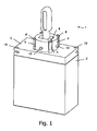
- FIG. 1 a switch 1 is shown in an embodiment corresponding to the device according to the invention in an oblique view.
- the switch 1 comprises a housing 2 with a housing upper side 3, a fastening projection 4 and four evenly distributed resilient tongues 5, each with a latching projection 6.
- the fastening projection 4 is designed as a circular base and simultaneously represents the bearing of the non-designated operating lever of the switch 1.
- the four resilient tongues 5 extend perpendicularly from the housing upper side 3 in the direction of the axis of the circular fastening projection 4 and are spaced therefrom.
- the fastening projection 4 further comprises four evenly distributed over the circumference nipple 13, which for holding the first time in FIG. 2 shown and executed in the manner of a bayonet closure sleeve 11 serve.
- two receivers for threaded pins are provided with the reference numeral 19.
- FIG. 2 the switch 1 is off FIG. 1 already shown in the pre-assembled state.
- Fixing projection 4 and tongues 5 were already from behind into a hole 10 of the Mounting plate 7 used.
- the arranged at the end of the tongues 5 latching projections 6 lock it with the upper edge of the bore 10 and thus lie on the front side 8 of the mounting plate 7.
- FIG. 2 also shows the still to be used sleeve 11.
- the sleeve 11 corresponds in its outer diameter approximately to the diameter of the bore 10 and has a recess 12 for each tongue 5. It can thus be inserted from above into the free space between the latching projection 4 and the bore 10.
- the attack in FIG. 1 shown nipple 13 in the four recesses 14 of the sleeve 11 a.
- the sleeve 11 further comprises a trim ring 16 which rests at least partially on the mounting plate 7 with its underside. The provisional stop, which is given by the engagement of the latching projections 6, is thus reinforced.
- FIG. 3 shows a side view of the fully assembled switch 1 from the FIGS. 1 and 2 .
- the two setscrews 18, which sit in the recesses 19 of the housing 2 tightened by rotation and thus support the switch 1 on the back 9 of the mounting plate 7 from.
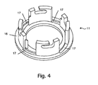
- FIG. 4 shows an oblique bottom view of the sleeve 11 from the FIGS. 2 to 3 , It can be seen that the trim ring 16 has four spirally outwardly facing grooves 17 on its underside, which serve to receive the latching projections 6. Due to the helical configuration of the grooves 17, the locking projections 6 are pressed in the locking of the executed in the manner of a bayonet sleeve 11 in the radial direction outward against the edge of the bore 10. The grooves 17 thus represent a further safeguard against the disengagement of the locking projections 6.
Landscapes
- Engineering & Computer Science (AREA)
- Power Engineering (AREA)
- Switch Cases, Indication, And Locking (AREA)
- Connection Of Plates (AREA)
Applications Claiming Priority (1)
| Application Number | Priority Date | Filing Date | Title |
|---|---|---|---|
| DE102008057147A DE102008057147B3 (de) | 2008-11-13 | 2008-11-13 | Vorrichtung zur Montage eines Schalters oder dergleichen an einer Montageplatte |
Publications (2)
| Publication Number | Publication Date |
|---|---|
| EP2190086A2 true EP2190086A2 (fr) | 2010-05-26 |
| EP2190086A3 EP2190086A3 (fr) | 2014-03-12 |
Family
ID=41821561
Family Applications (1)
| Application Number | Title | Priority Date | Filing Date |
|---|---|---|---|
| EP09009754.4A Withdrawn EP2190086A3 (fr) | 2008-11-13 | 2009-07-28 | Dispositif de montage d'un commutateur ou analogue sur une plaque de montage |
Country Status (4)
| Country | Link |
|---|---|
| US (1) | US8080750B2 (fr) |
| EP (1) | EP2190086A3 (fr) |
| DE (1) | DE102008057147B3 (fr) |
| RU (1) | RU2502165C2 (fr) |
Families Citing this family (5)
| Publication number | Priority date | Publication date | Assignee | Title |
|---|---|---|---|---|
| IT1391302B1 (it) * | 2008-10-28 | 2011-12-01 | Elbi Int Spa | Dispositivo rilevatore del livello di un liquido in un contenitore, in particolare del bagno di lavaggio in una macchina lavatrice |
| DE102011101759B4 (de) | 2011-05-17 | 2016-04-21 | Schaltbau Gmbh | Vorrichtung zur Montage eines elektrischen Bauteils, insbesondere eines Schalters, an einer Montageplatte |
| US20160053797A1 (en) * | 2014-08-20 | 2016-02-25 | Emerson Network Power, Energy Systems, North America, Inc. | Assemblies and methods for coupling components having slots and/or deformable stakes |
| DE102016213829A1 (de) * | 2016-07-27 | 2018-02-01 | Siemens Aktiengesellschaft | Fügbare Haltevorrichtung für Schaltanlagen |
| JP6989149B2 (ja) * | 2019-11-06 | 2022-01-05 | Necプラットフォームズ株式会社 | 部品取付構造、部品取付相手部材、部品固定部材、及び部品固定方法 |
Citations (2)
| Publication number | Priority date | Publication date | Assignee | Title |
|---|---|---|---|---|
| DE8207613U1 (de) | 1982-02-11 | 1982-11-25 | Baco Constructions Electriques, 67024 Strasbourg | Drehschalter oder dergleichen mit Befestigungsvorrichtung zur Anbringung an der Rückseite eines plattenförmigen Trägers |
| DE2807798C2 (de) | 1977-02-24 | 1984-11-29 | Izumi Denki Corp., Osaka | Vorrichtung zur Befestigung von elektrischen Bauteilen an einer Montageplatte |
Family Cites Families (7)
| Publication number | Priority date | Publication date | Assignee | Title |
|---|---|---|---|---|
| SU1026217A1 (ru) * | 1982-03-02 | 1983-06-30 | Ангарский электромеханический завод | Устройство дл креплени электрических аппаратов |
| FR2541738B1 (fr) * | 1983-02-28 | 1985-06-07 | Alsthom Cgee | Dispositif de fixation d'un objet sur une paroi |
| DE19832423B4 (de) * | 1998-06-09 | 2006-09-28 | Georg Schlegel Gmbh & Co. | Befehls- oder Meldegerät zum Einbau in eine Schalttafel oder dergleichen |
| DE19959339A1 (de) * | 1999-12-09 | 2001-06-21 | Ellenberger & Poensgen | Elektrisches Funktionsgerät, insbesondere Schutzschalter, zum Einsatz in der Luftfahrt |
| FI116866B (fi) * | 2004-01-19 | 2006-03-15 | Abb Oy | Kytkinlaitemoduuli |
| DE102004014593B4 (de) * | 2004-03-23 | 2006-02-02 | A. Raymond & Cie | Vorrichtung zum Befestigung an einem mit einem Gewindebolzen versehenen Trägerteil |
| ITVR20040040U1 (it) * | 2004-12-10 | 2005-03-10 | Vemer Siber Group S P A | Interruttore |
-
2008
- 2008-11-13 DE DE102008057147A patent/DE102008057147B3/de not_active Expired - Fee Related
-
2009
- 2009-07-28 EP EP09009754.4A patent/EP2190086A3/fr not_active Withdrawn
- 2009-09-23 RU RU2009136384/07A patent/RU2502165C2/ru not_active IP Right Cessation
- 2009-11-10 US US12/616,059 patent/US8080750B2/en not_active Expired - Fee Related
Patent Citations (2)
| Publication number | Priority date | Publication date | Assignee | Title |
|---|---|---|---|---|
| DE2807798C2 (de) | 1977-02-24 | 1984-11-29 | Izumi Denki Corp., Osaka | Vorrichtung zur Befestigung von elektrischen Bauteilen an einer Montageplatte |
| DE8207613U1 (de) | 1982-02-11 | 1982-11-25 | Baco Constructions Electriques, 67024 Strasbourg | Drehschalter oder dergleichen mit Befestigungsvorrichtung zur Anbringung an der Rückseite eines plattenförmigen Trägers |
Also Published As
| Publication number | Publication date |
|---|---|
| US20100116957A1 (en) | 2010-05-13 |
| EP2190086A3 (fr) | 2014-03-12 |
| DE102008057147B3 (de) | 2010-04-15 |
| RU2009136384A (ru) | 2011-03-27 |
| US8080750B2 (en) | 2011-12-20 |
| RU2502165C2 (ru) | 2013-12-20 |
Similar Documents
| Publication | Publication Date | Title |
|---|---|---|
| EP2376791B1 (fr) | Dispositif d'écartement et système de fixation avec dispositif d'écartement | |
| DE102011015563B4 (de) | Selbsttragende Winkelmutter | |
| DE102015122744A1 (de) | Verstellbare Distanzhülse | |
| EP2199473A1 (fr) | Corps de toilettes avec un support mural | |
| DE102008057147B3 (de) | Vorrichtung zur Montage eines Schalters oder dergleichen an einer Montageplatte | |
| DE102014224932A1 (de) | Haltevorrichtung für eine Schraubenmutter sowie Baueinheit mit einer solchen Haltevorrichtung | |
| EP0824170B1 (fr) | Dispositif de raccordement pour un accessoire de fixation utilisé pour attacher un élément sanitaire à une paroi | |
| DE102014113126A1 (de) | Toleranzausgleichsvorrichtung | |
| EP2071200B1 (fr) | Entretoise pour la fixation de panneaux et analogues | |
| EP2226430B1 (fr) | Dispositif de raccordement pour armatures d'écoulement | |
| DE1683207B1 (de) | Befestigungsvorrichtung fuer im Abstand veraenderliche Bauwerksverkleidungen | |
| DE102010030806A1 (de) | Befestigungseinrichtung | |
| EP2425066B1 (fr) | Cloisonnement pour aménagement intérieur | |
| EP1981384A1 (fr) | Dispositif de maintien conçu pour maintenir un appareil encastrable sur un plan de travail | |
| WO2004084342A1 (fr) | Antenne a boitier en plastique | |
| EP3470689B1 (fr) | Dispositif de fixation et procédé de montage d'un capteur dans une ouverture | |
| DE19842512C1 (de) | Anordnung zur Installation einer Einbaukomponente in eine Wandung oder einen Hohlkörper | |
| EP0866183B1 (fr) | Dispositif d' installation pour l'actionnement d'un appareil sanitaire | |
| DE102020119470B4 (de) | Haltevorrichtung zur lösbaren Festlegung eines Funktionselements an einer Oberfläche | |
| EP0775874B1 (fr) | Dispositif de fixation | |
| DE102018114585A1 (de) | Schubkasten und Verfahren zur Montage einer Rückwand an einer Seitenzarge eines Schubkastens | |
| DE102011101759A1 (de) | Vorrichtung zur Montage eines Schalters oder dergleichen an einer Montageplatte | |
| EP2503081A2 (fr) | Système de plaques de support | |
| EP3211160B1 (fr) | Rosette | |
| DE10136200B4 (de) | Befestigungsschraube |
Legal Events
| Date | Code | Title | Description |
|---|---|---|---|
| PUAI | Public reference made under article 153(3) epc to a published international application that has entered the european phase |
Free format text: ORIGINAL CODE: 0009012 |
|
| AK | Designated contracting states |
Kind code of ref document: A2 Designated state(s): AT BE BG CH CY CZ DE DK EE ES FI FR GB GR HR HU IE IS IT LI LT LU LV MC MK MT NL NO PL PT RO SE SI SK SM TR |
|
| AX | Request for extension of the european patent |
Extension state: AL BA RS |
|
| PUAL | Search report despatched |
Free format text: ORIGINAL CODE: 0009013 |
|
| AK | Designated contracting states |
Kind code of ref document: A3 Designated state(s): AT BE BG CH CY CZ DE DK EE ES FI FR GB GR HR HU IE IS IT LI LT LU LV MC MK MT NL NO PL PT RO SE SI SK SM TR |
|
| AX | Request for extension of the european patent |
Extension state: AL BA RS |
|
| RIC1 | Information provided on ipc code assigned before grant |
Ipc: H02B 1/048 20060101ALI20140131BHEP Ipc: H02B 1/044 20060101AFI20140131BHEP |
|
| 17P | Request for examination filed |
Effective date: 20140828 |
|
| RBV | Designated contracting states (corrected) |
Designated state(s): AT BE BG CH CY CZ DE DK EE ES FI FR GB GR HR HU IE IS IT LI LT LU LV MC MK MT NL NO PL PT RO SE SI SK SM TR |
|
| RIC1 | Information provided on ipc code assigned before grant |
Ipc: H02B 1/044 20060101AFI20170712BHEP Ipc: H02B 1/048 20060101ALI20170712BHEP |
|
| GRAP | Despatch of communication of intention to grant a patent |
Free format text: ORIGINAL CODE: EPIDOSNIGR1 |
|
| INTG | Intention to grant announced |
Effective date: 20170830 |
|
| STAA | Information on the status of an ep patent application or granted ep patent |
Free format text: STATUS: THE APPLICATION IS DEEMED TO BE WITHDRAWN |
|
| 18D | Application deemed to be withdrawn |
Effective date: 20180110 |