EP2190105A2 - Convertisseur de fréquence pour contrôler un moteur électrique - Google Patents
Convertisseur de fréquence pour contrôler un moteur électrique Download PDFInfo
- Publication number
- EP2190105A2 EP2190105A2 EP09176446A EP09176446A EP2190105A2 EP 2190105 A2 EP2190105 A2 EP 2190105A2 EP 09176446 A EP09176446 A EP 09176446A EP 09176446 A EP09176446 A EP 09176446A EP 2190105 A2 EP2190105 A2 EP 2190105A2
- Authority
- EP
- European Patent Office
- Prior art keywords
- adapter
- housing
- frequency converter
- motor
- electrical connection
- Prior art date
- Legal status (The legal status is an assumption and is not a legal conclusion. Google has not performed a legal analysis and makes no representation as to the accuracy of the status listed.)
- Granted
Links
Images


Classifications
-
- H—ELECTRICITY
- H02—GENERATION; CONVERSION OR DISTRIBUTION OF ELECTRIC POWER
- H02K—DYNAMO-ELECTRIC MACHINES
- H02K5/00—Casings; Enclosures; Supports
- H02K5/04—Casings or enclosures characterised by the shape, form or construction thereof
- H02K5/22—Auxiliary parts of casings not covered by groups H02K5/06-H02K5/20, e.g. shaped to form connection boxes or terminal boxes
- H02K5/225—Terminal boxes or connection arrangements
-
- H—ELECTRICITY
- H02—GENERATION; CONVERSION OR DISTRIBUTION OF ELECTRIC POWER
- H02K—DYNAMO-ELECTRIC MACHINES
- H02K11/00—Structural association of dynamo-electric machines with electric components or with devices for shielding, monitoring or protection
- H02K11/30—Structural association with control circuits or drive circuits
- H02K11/33—Drive circuits, e.g. power electronics
Definitions
- the invention relates to a frequency converter for controlling an electric motor with an intended for mounting on the motor housing inverter housing, the frequency converter is connected on the input side with at least one guided into the inverter housing power cord for connection to the mains, and the output side via connectors releasably connected to the electric motor.
- Frequency inverters of the type discussed here are used as static frequency converters for operating electric motors, in particular asynchronous machines, wherein the connection of frequency converter and electric motor to a structural unit with respect to electromagnetic interference has significant advantages over the separate installation of the drive in a separate cabinet.
- the frequency converter is accommodated in a total of an inverter housing referred to as a terminal box.
- the line-side connection cable of the frequency inverter is led out of the converter housing as a grown cable.
- a socket with plug pins accommodated therein is formed on the converter housing.
- the frequency converter according to the present invention has the advantage of being mountable on a multiplicity of different motor housings and thus very flexibly usable without any special measures for mechanical adaptation.
- the converter housing is fixed by means of a mechanically connected on the one hand with the motor housing and on the other hand with the inverter housing, electrical connection elements comprehensive adapter to the motor housing.
- the adapter preferably comprises a circuit carrier on which first electrical connection elements for connection to the motor connection lines and second electrical connection elements for connection to the frequency converter are present, wherein in a particularly practicable embodiment the first electrical connection elements are designed as screw terminal block and the second electrical connection elements as plug connector are, and wherein the individual contacts of the screw terminal block and the connector strip are electrically connected to each other by conductors on the circuit board.
- a tolerance compensation between the circuit carrier of the adapter and a the electrical connection elements of the frequency converter having the printed circuit board is achieved in that the adapter comprises a substantially plate-shaped adapter base, which has a central Has opening, and that the circuit carrier is floatingly mounted relative to the adapter base.
- the printed circuit board fixed in the converter housing has firmly connected to this positioning pins, which positioning holes are assigned to the circuit carrier of the adapter such that when assembling the inverter housing with the adapter, the circuit carrier is positioned so that a perfect mesh and electrical Contact the connector part of the adapter with the associated mating connector part of the drive takes place.
- Fig. 1 is an inventive frequency converter to see, which is mounted on an electric motor.
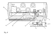
- the converter housing 2 consists of a lower housing part 2 a, which also has to fulfill various functional aspects, and a housing cover 2 b, which essentially has only the task of closing the converter housing 2.
- the housing base 2a includes, as in the sectional view in Fig. 4 can be seen, a printed circuit board 9 on which the electronic components of the control and power electronics of the frequency converter are added.
- the lower housing part 2a which preferably consists of a material with a good thermal conductivity, ie, for example, made of aluminum, is provided on its lower outer wall with cooling fins 12, via which the heat loss, in particular in the power components 13 of the frequency converter is dissipated.
- the power devices 13 are so positioned on the circuit board 9 that they are in direct contact with this lower outer wall.
- the at least one mains connection line 14 and further control and / or sensor lines 14 ' are guided by cable glands into the interior of the converter housing 2.
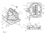
- the adapter 5 itself is in Fig. 3 shown in different illustrations. It comprises a substantially plate-shaped adapter base 5a, which is a has central opening 8.
- the adapter base part 5a can consist of a metallic material such as aluminum or else of a non-metallic material, for example of a glass-fiber reinforced plastic.
- the central opening 8 of the adapter base part 5a is surrounded by a collar 5b molded integrally therewith, which has a sealing element 12 in the upper area of its outer side for sealing against the converter housing 2.
- the sealing element 12 is formed as a received in a circumferential groove on the outside of the collar 5b O-ring seal 12.
- the outer contour of the collar 5 b is designed to fit a corresponding opening in the lower outer wall of the housing lower part 2 a of the converter housing 2 so that it closes tightly when placed on the adapter 5.
- the adapter 5 With the help of the adapter 5, it is possible to mount the frequency converter on many different motor housings 1. Basically, all that is required for this is that the adapter base part 5a is able to completely cover the opening of the connection piece 1a of the motor housing 1. The screw holes in the Adaptergundteil 5a are then each drilled as it corresponds to the threaded hole image of the connecting piece 1a of the respective motor housing 1. In 3 a) and b) this is indicated by the marking of several possible Anschraubitz 16. In the interior of the collar 5b of the adapter 5, a circuit carrier 6, for example in the form of a printed circuit board is accommodated, which partially covers the central opening 8 surrounded by the collar 5b.
- a screw terminal block 7 and a connector part 4 arranged in this case a power strip.
- the connector part 4 is used for electrical contacting of a corresponding mating connector part 3, so in this case a socket strip on the circuit board 9 of the frequency.
- the individual contacts of the screw terminal block 7 and of the connector part 4 are electrically connected to one another by conductors on the circuit carrier 6, so that an electrical connection of the motor connection lines to the frequency converter can be established via this.
- the circuit carrier 6 is mounted floating relative to the adapter base 5a.
- the mounting holes 17 in the circuit carrier 6 are designed in excess of diameter relative to associated positioning sleeves 18 on the adapter base 5a, and the mounting screws 19 reach when tightening their block position on the positioning sleeves 18 before a frictional connection of the screw heads can be achieved with the circuit carrier 6.
- the circuit carrier 6 is thus set in its height position, in its lateral position, however, freely movable to a certain extent.
Landscapes
- Engineering & Computer Science (AREA)
- Power Engineering (AREA)
- Microelectronics & Electronic Packaging (AREA)
- Motor Or Generator Frames (AREA)
- Inverter Devices (AREA)
- Control Of Ac Motors In General (AREA)
Applications Claiming Priority (1)
| Application Number | Priority Date | Filing Date | Title |
|---|---|---|---|
| DE102008058511A DE102008058511A1 (de) | 2008-11-21 | 2008-11-21 | Frequenzumrichter zum Steuern eines Elektromotors |
Publications (3)
| Publication Number | Publication Date |
|---|---|
| EP2190105A2 true EP2190105A2 (fr) | 2010-05-26 |
| EP2190105A3 EP2190105A3 (fr) | 2015-04-22 |
| EP2190105B1 EP2190105B1 (fr) | 2017-07-19 |
Family
ID=41338698
Family Applications (1)
| Application Number | Title | Priority Date | Filing Date |
|---|---|---|---|
| EP09176446.4A Active EP2190105B1 (fr) | 2008-11-21 | 2009-11-19 | Convertisseur de fréquence pour contrôler un moteur électrique |
Country Status (3)
| Country | Link |
|---|---|
| US (1) | US8278790B2 (fr) |
| EP (1) | EP2190105B1 (fr) |
| DE (1) | DE102008058511A1 (fr) |
Cited By (3)
| Publication number | Priority date | Publication date | Assignee | Title |
|---|---|---|---|---|
| WO2012123108A3 (fr) * | 2011-03-14 | 2013-04-25 | Wilo Se | Zone de raccordement électrique d'un moteur électrique |
| EP3714533A1 (fr) * | 2017-11-23 | 2020-09-30 | KSB SE & Co. KGaA | Électronique de moteur intégrée |
| AT523611A1 (de) * | 2020-03-05 | 2021-09-15 | Avl List Gmbh | Schaltschrank für eine elektrische Umrichterbaugruppe |
Families Citing this family (28)
| Publication number | Priority date | Publication date | Assignee | Title |
|---|---|---|---|---|
| DE102010051891A1 (de) * | 2010-11-22 | 2012-05-24 | Kostal Industrie Elektrik Gmbh | Frequenzumrichter zum Steuern eines Elektromotors |
| JP5270702B2 (ja) * | 2011-02-14 | 2013-08-21 | トヨタ自動車株式会社 | 車両用機器搭載構造 |
| JP5539256B2 (ja) * | 2011-04-14 | 2014-07-02 | 日立建機株式会社 | 電動モータ |
| JP2013070028A (ja) * | 2011-09-07 | 2013-04-18 | Hitachi Automotive Systems Ltd | 電子制御装置 |
| DE102011117261A1 (de) * | 2011-10-27 | 2013-05-02 | Schneider Electric Automation Gmbh | Serielle Verkabelung von Elektromotoren mit integrierten Elektronikplatinen |
| US9030066B2 (en) * | 2011-10-31 | 2015-05-12 | Regal Beloit America, Inc. | Electric motor with multiple power access |
| DE102011085872B4 (de) * | 2011-11-07 | 2023-03-23 | Lenze Se | Frequenzumrichter und Federelement hierfür |
| EP2626566B1 (fr) * | 2012-02-08 | 2021-07-28 | Grundfos Holding A/S | Moteur électrique |
| US9373986B2 (en) * | 2012-11-02 | 2016-06-21 | Rockwell Automation Technologies, Inc. | Method for providing servo motor rear bearing support, space for internal electronic packaging and IP sealing between motor and externally attached devices |
| EP2728985B1 (fr) * | 2012-11-02 | 2018-01-31 | Siemens Schweiz AG | Entraînement de réglage avec raccord enfichable électrique |
| US9048708B2 (en) * | 2012-11-05 | 2015-06-02 | Rockwell Automation Technologies, Inc. | Integrated drive-motor assembly with IP seal and enhanced heat transfer |
| DE102013205897B4 (de) * | 2013-04-03 | 2022-11-10 | Lenze Se | Antriebssystem |
| DE102013207578A1 (de) * | 2013-04-25 | 2014-10-30 | Robert Bosch Gmbh | Stellantriebsanordnung mit einem Steckverbinder sowie Steckeranordnung für eine Stellantriebsanordnung und Herstellungsverfahren einer solchen |
| DE102014106452A1 (de) * | 2014-05-08 | 2015-11-12 | Dr. Ing. H.C. F. Porsche Aktiengesellschaft | Gehäuseanordnung für ein Hochvolt-Aggregat im KFZ-Bereich |
| US9444304B2 (en) * | 2014-07-21 | 2016-09-13 | Caterpillar Inc. | Generator set having adjustable terminal box |
| DE102015119002A1 (de) * | 2015-11-05 | 2017-05-11 | Ebm-Papst Mulfingen Gmbh & Co. Kg | Elektronikeinheit |
| JP6583027B2 (ja) * | 2016-02-02 | 2019-10-02 | 日本精工株式会社 | 電動モータとその制御装置に収納される基板との接続構造 |
| USD862389S1 (en) * | 2017-03-10 | 2019-10-08 | Norman R. Byrne | Low voltage outlet |
| CN107086727A (zh) * | 2017-06-13 | 2017-08-22 | 浙江佳雪微特电机集团有限责任公司 | 一种大功率永磁无刷水泵电机 |
| USD918141S1 (en) * | 2018-06-22 | 2021-05-04 | Siemens Aktiengesellschaft | Electric motor |
| USD909301S1 (en) * | 2018-11-19 | 2021-02-02 | Saccardo Elettromeccanica S.R.L. | Electric motor |
| US11705774B2 (en) * | 2018-12-27 | 2023-07-18 | Abb Schweiz Ag | Industrial electrical machine system and electronics module |
| USD922320S1 (en) * | 2019-10-31 | 2021-06-15 | Wittenstein Se | Converter with motor |
| CN215344309U (zh) * | 2021-06-17 | 2021-12-28 | 台州正立电机有限公司 | 一种集智能控制的永磁同步电机一体机结构 |
| DE102022107373A1 (de) | 2022-03-29 | 2023-10-05 | KSB SE & Co. KGaA | Pumpe mit Motorgehäuse und lösbar auf dem Motorgehäuse angeordneten Elektronikgehäuse |
| US12578356B2 (en) | 2022-04-11 | 2026-03-17 | Rockwell Automation Technologies, Inc. | Embedded vibration and shock sensor with an integrated motor drive assembly |
| DE102022212114A1 (de) * | 2022-11-15 | 2024-05-16 | Volkswagen Aktiengesellschaft | Wechselrichter und Antriebsstrang eines Kraftfahrzeugs |
| DE102023003216A1 (de) * | 2023-08-04 | 2025-02-06 | KSB SE & Co. KGaA | Elektrische Antriebseinheit für eine Pumpe sowie Pumpe |
Citations (1)
| Publication number | Priority date | Publication date | Assignee | Title |
|---|---|---|---|---|
| DE3642724A1 (de) | 1986-12-13 | 1988-06-23 | Grundfos Int | Elektromotor mit einem frequenzumrichter zur steuerung der motorbetriebsgroessen |
Family Cites Families (10)
| Publication number | Priority date | Publication date | Assignee | Title |
|---|---|---|---|---|
| US4451750A (en) * | 1981-02-03 | 1984-05-29 | Elektro-Mechanik Gmbh | Protective arrangement for a plug-connected electric motor sealed against pressure, vapors and radiation |
| DE29615095U1 (de) * | 1996-08-30 | 1996-10-24 | Harting Elektronik Gmbh, 32339 Espelkamp | Elektrische Steckverbindung |
| DE19704226B4 (de) * | 1997-02-05 | 2004-09-30 | Sew-Eurodrive Gmbh & Co. Kg | Klemmdeckelumrichter |
| DE10109797B4 (de) * | 2001-03-01 | 2019-03-21 | Sew-Eurodrive Gmbh & Co Kg | Umrichtermotor, umfassend einen Motor, mindestens ein Zwischenteil und einen Umrichter |
| EP1363026A3 (fr) * | 2002-04-26 | 2004-09-01 | Denso Corporation | Onduleur intégré moteur pour un véhicule automobile |
| JP2004023841A (ja) * | 2002-06-13 | 2004-01-22 | Mitsuba Corp | モータ |
| DE10332392B4 (de) * | 2002-09-10 | 2014-12-04 | Sew-Eurodrive Gmbh & Co Kg | Feldgerät mit einem Gehäuse |
| JP4161074B2 (ja) * | 2004-02-02 | 2008-10-08 | 三菱電機株式会社 | 電動式パワーステアリング装置 |
| DE102005015318B4 (de) * | 2005-04-01 | 2010-01-07 | Sew-Eurodrive Gmbh & Co. Kg | Gehäuseeinheit mit Öffnungs- und Schließvorrichtung und elektrisches Gerät |
| JP4631564B2 (ja) * | 2005-06-29 | 2011-02-16 | 三菱電機株式会社 | フローティングナット並びにプリント基板 |
-
2008
- 2008-11-21 DE DE102008058511A patent/DE102008058511A1/de not_active Withdrawn
-
2009
- 2009-11-19 EP EP09176446.4A patent/EP2190105B1/fr active Active
- 2009-11-20 US US12/622,905 patent/US8278790B2/en active Active
Patent Citations (1)
| Publication number | Priority date | Publication date | Assignee | Title |
|---|---|---|---|---|
| DE3642724A1 (de) | 1986-12-13 | 1988-06-23 | Grundfos Int | Elektromotor mit einem frequenzumrichter zur steuerung der motorbetriebsgroessen |
Cited By (5)
| Publication number | Priority date | Publication date | Assignee | Title |
|---|---|---|---|---|
| WO2012123108A3 (fr) * | 2011-03-14 | 2013-04-25 | Wilo Se | Zone de raccordement électrique d'un moteur électrique |
| DE102011013952B4 (de) | 2011-03-14 | 2023-12-07 | Wilo Se | Elektromotor |
| EP3714533A1 (fr) * | 2017-11-23 | 2020-09-30 | KSB SE & Co. KGaA | Électronique de moteur intégrée |
| AT523611A1 (de) * | 2020-03-05 | 2021-09-15 | Avl List Gmbh | Schaltschrank für eine elektrische Umrichterbaugruppe |
| AT523611B1 (de) * | 2020-03-05 | 2021-12-15 | Avl List Gmbh | Schaltschrank für eine elektrische Umrichterbaugruppe |
Also Published As
| Publication number | Publication date |
|---|---|
| US8278790B2 (en) | 2012-10-02 |
| US20100127602A1 (en) | 2010-05-27 |
| EP2190105A3 (fr) | 2015-04-22 |
| EP2190105B1 (fr) | 2017-07-19 |
| DE102008058511A1 (de) | 2010-05-27 |
Similar Documents
| Publication | Publication Date | Title |
|---|---|---|
| EP2190105B1 (fr) | Convertisseur de fréquence pour contrôler un moteur électrique | |
| DE102019002350B3 (de) | Modulares elektronikgehäusekonzept | |
| EP0882318B1 (fr) | Connecteur electrique multiple multipolaire et partie de douille associee | |
| EP1269809B1 (fr) | Appareil electrique comportant des modules pouvant etre montes l'un a cote de l'autre | |
| EP2043234B1 (fr) | Moteur électrique | |
| DE4437316C2 (de) | Dezentrale Ein/Ausgabebaugruppe für elektronische Steuerungen | |
| EP0909122B1 (fr) | Appareil électrique | |
| EP2645504A2 (fr) | Prise de raccordement | |
| DE4422113C2 (de) | Elektronikmodul | |
| DE102004039682A1 (de) | Anschlussvorrichtung für eine elektrische Maschine | |
| EP2359439A1 (fr) | Système de raccordement pour réaliser des branchements sur des conducteurs continus | |
| DE202008013992U1 (de) | Modulare Montagebasis für elektrische Geräte | |
| EP2456051B1 (fr) | Commutateur de fréquence destiné à commander un moteur électrique | |
| DE10340297B4 (de) | Verbindugsanordnung zur Verbindung von aktiven und passiven elektrischen und elektronischen Bauelementen | |
| EP2183826A1 (fr) | Dispositif de raccordement électrique pour contacts conducteurs, notamment contacts à couteaux | |
| DE3727940C1 (de) | Kabelkanal fuer Textilmaschinen,insbesondere Spinn- oder Zwirnmaschinen | |
| DE2336878C3 (de) | Elektrisches Gerät | |
| DE19911196C2 (de) | Schaltschrank-Elektrifizierungseinrichtung | |
| DE202007019214U1 (de) | Netzstecker | |
| DE102014215058A1 (de) | Anschlussvorrichtung zum Anschließen elektrischer Leitungen und Verfahren zur Montage einer derartigen Anschlussvorrichtung | |
| EP1597951B1 (fr) | Appareil electronique a dissipation de chaleur plus sure | |
| DE10259761A1 (de) | Lüftergehäuse | |
| DE102014004798B4 (de) | Elektrisches Gerät | |
| EP2738454B1 (fr) | Lampe dotée d'un boîtier de lampe et d'un circuit électronique | |
| EP3940927A1 (fr) | Dispositif d'entraînement, en particulier pour un système de compresseur destiné à la génération de l'air comprimé dans un frein de véhicule |
Legal Events
| Date | Code | Title | Description |
|---|---|---|---|
| PUAI | Public reference made under article 153(3) epc to a published international application that has entered the european phase |
Free format text: ORIGINAL CODE: 0009012 |
|
| AK | Designated contracting states |
Kind code of ref document: A2 Designated state(s): AT BE BG CH CY CZ DE DK EE ES FI FR GB GR HR HU IE IS IT LI LT LU LV MC MK MT NL NO PL PT RO SE SI SK SM TR |
|
| AX | Request for extension of the european patent |
Extension state: AL BA RS |
|
| PUAL | Search report despatched |
Free format text: ORIGINAL CODE: 0009013 |
|
| AK | Designated contracting states |
Kind code of ref document: A3 Designated state(s): AT BE BG CH CY CZ DE DK EE ES FI FR GB GR HR HU IE IS IT LI LT LU LV MC MK MT NL NO PL PT RO SE SI SK SM TR |
|
| AX | Request for extension of the european patent |
Extension state: AL BA RS |
|
| RIC1 | Information provided on ipc code assigned before grant |
Ipc: H02K 11/00 20060101AFI20150319BHEP Ipc: H02K 5/22 20060101ALI20150319BHEP |
|
| 17P | Request for examination filed |
Effective date: 20150918 |
|
| RBV | Designated contracting states (corrected) |
Designated state(s): AT BE BG CH CY CZ DE DK EE ES FI FR GB GR HR HU IE IS IT LI LT LU LV MC MK MT NL NO PL PT RO SE SI SK SM TR |
|
| 17Q | First examination report despatched |
Effective date: 20160819 |
|
| REG | Reference to a national code |
Ref country code: DE Ref legal event code: R079 Ref document number: 502009014166 Country of ref document: DE Free format text: PREVIOUS MAIN CLASS: H02K0011000000 Ipc: H02K0011330000 |
|
| GRAP | Despatch of communication of intention to grant a patent |
Free format text: ORIGINAL CODE: EPIDOSNIGR1 |
|
| RIC1 | Information provided on ipc code assigned before grant |
Ipc: H02K 11/33 20160101AFI20170328BHEP Ipc: H02K 5/22 20060101ALI20170328BHEP |
|
| INTG | Intention to grant announced |
Effective date: 20170425 |
|
| GRAS | Grant fee paid |
Free format text: ORIGINAL CODE: EPIDOSNIGR3 |
|
| GRAA | (expected) grant |
Free format text: ORIGINAL CODE: 0009210 |
|
| AK | Designated contracting states |
Kind code of ref document: B1 Designated state(s): AT BE BG CH CY CZ DE DK EE ES FI FR GB GR HR HU IE IS IT LI LT LU LV MC MK MT NL NO PL PT RO SE SI SK SM TR |
|
| REG | Reference to a national code |
Ref country code: GB Ref legal event code: FG4D Free format text: NOT ENGLISH |
|
| REG | Reference to a national code |
Ref country code: CH Ref legal event code: EP |
|
| REG | Reference to a national code |
Ref country code: IE Ref legal event code: FG4D Free format text: LANGUAGE OF EP DOCUMENT: GERMAN |
|
| REG | Reference to a national code |
Ref country code: CH Ref legal event code: NV Representative=s name: ALDO ROEMPLER PATENTANWALT, CH Ref country code: AT Ref legal event code: REF Ref document number: 911285 Country of ref document: AT Kind code of ref document: T Effective date: 20170815 |
|
| REG | Reference to a national code |
Ref country code: DE Ref legal event code: R096 Ref document number: 502009014166 Country of ref document: DE |
|
| REG | Reference to a national code |
Ref country code: NL Ref legal event code: FP |
|
| REG | Reference to a national code |
Ref country code: FR Ref legal event code: PLFP Year of fee payment: 9 |
|
| REG | Reference to a national code |
Ref country code: LT Ref legal event code: MG4D |
|
| PG25 | Lapsed in a contracting state [announced via postgrant information from national office to epo] |
Ref country code: FI Free format text: LAPSE BECAUSE OF FAILURE TO SUBMIT A TRANSLATION OF THE DESCRIPTION OR TO PAY THE FEE WITHIN THE PRESCRIBED TIME-LIMIT Effective date: 20170719 Ref country code: HR Free format text: LAPSE BECAUSE OF FAILURE TO SUBMIT A TRANSLATION OF THE DESCRIPTION OR TO PAY THE FEE WITHIN THE PRESCRIBED TIME-LIMIT Effective date: 20170719 Ref country code: LT Free format text: LAPSE BECAUSE OF FAILURE TO SUBMIT A TRANSLATION OF THE DESCRIPTION OR TO PAY THE FEE WITHIN THE PRESCRIBED TIME-LIMIT Effective date: 20170719 Ref country code: NO Free format text: LAPSE BECAUSE OF FAILURE TO SUBMIT A TRANSLATION OF THE DESCRIPTION OR TO PAY THE FEE WITHIN THE PRESCRIBED TIME-LIMIT Effective date: 20171019 Ref country code: SE Free format text: LAPSE BECAUSE OF FAILURE TO SUBMIT A TRANSLATION OF THE DESCRIPTION OR TO PAY THE FEE WITHIN THE PRESCRIBED TIME-LIMIT Effective date: 20170719 |
|
| PG25 | Lapsed in a contracting state [announced via postgrant information from national office to epo] |
Ref country code: BG Free format text: LAPSE BECAUSE OF FAILURE TO SUBMIT A TRANSLATION OF THE DESCRIPTION OR TO PAY THE FEE WITHIN THE PRESCRIBED TIME-LIMIT Effective date: 20171019 Ref country code: IS Free format text: LAPSE BECAUSE OF FAILURE TO SUBMIT A TRANSLATION OF THE DESCRIPTION OR TO PAY THE FEE WITHIN THE PRESCRIBED TIME-LIMIT Effective date: 20171119 Ref country code: LV Free format text: LAPSE BECAUSE OF FAILURE TO SUBMIT A TRANSLATION OF THE DESCRIPTION OR TO PAY THE FEE WITHIN THE PRESCRIBED TIME-LIMIT Effective date: 20170719 Ref country code: GR Free format text: LAPSE BECAUSE OF FAILURE TO SUBMIT A TRANSLATION OF THE DESCRIPTION OR TO PAY THE FEE WITHIN THE PRESCRIBED TIME-LIMIT Effective date: 20171020 Ref country code: PL Free format text: LAPSE BECAUSE OF FAILURE TO SUBMIT A TRANSLATION OF THE DESCRIPTION OR TO PAY THE FEE WITHIN THE PRESCRIBED TIME-LIMIT Effective date: 20170719 Ref country code: ES Free format text: LAPSE BECAUSE OF FAILURE TO SUBMIT A TRANSLATION OF THE DESCRIPTION OR TO PAY THE FEE WITHIN THE PRESCRIBED TIME-LIMIT Effective date: 20170719 |
|
| REG | Reference to a national code |
Ref country code: DE Ref legal event code: R097 Ref document number: 502009014166 Country of ref document: DE |
|
| PG25 | Lapsed in a contracting state [announced via postgrant information from national office to epo] |
Ref country code: RO Free format text: LAPSE BECAUSE OF FAILURE TO SUBMIT A TRANSLATION OF THE DESCRIPTION OR TO PAY THE FEE WITHIN THE PRESCRIBED TIME-LIMIT Effective date: 20170719 Ref country code: CZ Free format text: LAPSE BECAUSE OF FAILURE TO SUBMIT A TRANSLATION OF THE DESCRIPTION OR TO PAY THE FEE WITHIN THE PRESCRIBED TIME-LIMIT Effective date: 20170719 Ref country code: DK Free format text: LAPSE BECAUSE OF FAILURE TO SUBMIT A TRANSLATION OF THE DESCRIPTION OR TO PAY THE FEE WITHIN THE PRESCRIBED TIME-LIMIT Effective date: 20170719 |
|
| PLBE | No opposition filed within time limit |
Free format text: ORIGINAL CODE: 0009261 |
|
| STAA | Information on the status of an ep patent application or granted ep patent |
Free format text: STATUS: NO OPPOSITION FILED WITHIN TIME LIMIT |
|
| PG25 | Lapsed in a contracting state [announced via postgrant information from national office to epo] |
Ref country code: SK Free format text: LAPSE BECAUSE OF FAILURE TO SUBMIT A TRANSLATION OF THE DESCRIPTION OR TO PAY THE FEE WITHIN THE PRESCRIBED TIME-LIMIT Effective date: 20170719 Ref country code: EE Free format text: LAPSE BECAUSE OF FAILURE TO SUBMIT A TRANSLATION OF THE DESCRIPTION OR TO PAY THE FEE WITHIN THE PRESCRIBED TIME-LIMIT Effective date: 20170719 Ref country code: SM Free format text: LAPSE BECAUSE OF FAILURE TO SUBMIT A TRANSLATION OF THE DESCRIPTION OR TO PAY THE FEE WITHIN THE PRESCRIBED TIME-LIMIT Effective date: 20170719 |
|
| 26N | No opposition filed |
Effective date: 20180420 |
|
| PG25 | Lapsed in a contracting state [announced via postgrant information from national office to epo] |
Ref country code: MC Free format text: LAPSE BECAUSE OF FAILURE TO SUBMIT A TRANSLATION OF THE DESCRIPTION OR TO PAY THE FEE WITHIN THE PRESCRIBED TIME-LIMIT Effective date: 20170719 |
|
| PG25 | Lapsed in a contracting state [announced via postgrant information from national office to epo] |
Ref country code: SI Free format text: LAPSE BECAUSE OF FAILURE TO SUBMIT A TRANSLATION OF THE DESCRIPTION OR TO PAY THE FEE WITHIN THE PRESCRIBED TIME-LIMIT Effective date: 20170719 |
|
| REG | Reference to a national code |
Ref country code: IE Ref legal event code: MM4A |
|
| PG25 | Lapsed in a contracting state [announced via postgrant information from national office to epo] |
Ref country code: MT Free format text: LAPSE BECAUSE OF FAILURE TO SUBMIT A TRANSLATION OF THE DESCRIPTION OR TO PAY THE FEE WITHIN THE PRESCRIBED TIME-LIMIT Effective date: 20170719 |
|
| PG25 | Lapsed in a contracting state [announced via postgrant information from national office to epo] |
Ref country code: IE Free format text: LAPSE BECAUSE OF NON-PAYMENT OF DUE FEES Effective date: 20171119 |
|
| PG25 | Lapsed in a contracting state [announced via postgrant information from national office to epo] |
Ref country code: HU Free format text: LAPSE BECAUSE OF FAILURE TO SUBMIT A TRANSLATION OF THE DESCRIPTION OR TO PAY THE FEE WITHIN THE PRESCRIBED TIME-LIMIT; INVALID AB INITIO Effective date: 20091119 |
|
| PG25 | Lapsed in a contracting state [announced via postgrant information from national office to epo] |
Ref country code: CY Free format text: LAPSE BECAUSE OF NON-PAYMENT OF DUE FEES Effective date: 20170719 |
|
| PG25 | Lapsed in a contracting state [announced via postgrant information from national office to epo] |
Ref country code: MK Free format text: LAPSE BECAUSE OF FAILURE TO SUBMIT A TRANSLATION OF THE DESCRIPTION OR TO PAY THE FEE WITHIN THE PRESCRIBED TIME-LIMIT Effective date: 20170719 |
|
| PG25 | Lapsed in a contracting state [announced via postgrant information from national office to epo] |
Ref country code: PT Free format text: LAPSE BECAUSE OF FAILURE TO SUBMIT A TRANSLATION OF THE DESCRIPTION OR TO PAY THE FEE WITHIN THE PRESCRIBED TIME-LIMIT Effective date: 20170719 |
|
| PGFP | Annual fee paid to national office [announced via postgrant information from national office to epo] |
Ref country code: LU Payment date: 20241126 Year of fee payment: 16 |
|
| PGFP | Annual fee paid to national office [announced via postgrant information from national office to epo] |
Ref country code: NL Payment date: 20251027 Year of fee payment: 17 |
|
| REG | Reference to a national code |
Ref country code: CH Ref legal event code: U11 Free format text: ST27 STATUS EVENT CODE: U-0-0-U10-U11 (AS PROVIDED BY THE NATIONAL OFFICE) Effective date: 20251201 |
|
| PGFP | Annual fee paid to national office [announced via postgrant information from national office to epo] |
Ref country code: DE Payment date: 20251127 Year of fee payment: 17 |
|
| PGFP | Annual fee paid to national office [announced via postgrant information from national office to epo] |
Ref country code: GB Payment date: 20251112 Year of fee payment: 17 |
|
| PGFP | Annual fee paid to national office [announced via postgrant information from national office to epo] |
Ref country code: AT Payment date: 20251113 Year of fee payment: 17 |
|
| PGFP | Annual fee paid to national office [announced via postgrant information from national office to epo] |
Ref country code: IT Payment date: 20251124 Year of fee payment: 17 |
|
| PGFP | Annual fee paid to national office [announced via postgrant information from national office to epo] |
Ref country code: FR Payment date: 20251129 Year of fee payment: 17 |
|
| PGFP | Annual fee paid to national office [announced via postgrant information from national office to epo] |
Ref country code: BE Payment date: 20251124 Year of fee payment: 17 Ref country code: TR Payment date: 20251002 Year of fee payment: 17 |
|
| PGFP | Annual fee paid to national office [announced via postgrant information from national office to epo] |
Ref country code: CH Payment date: 20251201 Year of fee payment: 17 |
|
| PG25 | Lapsed in a contracting state [announced via postgrant information from national office to epo] |
Ref country code: LU Free format text: LAPSE BECAUSE OF NON-PAYMENT OF DUE FEES Effective date: 20251119 |