EP2190132B1 - Frontend für ein mobiles Kommunikationsgerät - Google Patents
Frontend für ein mobiles Kommunikationsgerät Download PDFInfo
- Publication number
- EP2190132B1 EP2190132B1 EP10154412.0A EP10154412A EP2190132B1 EP 2190132 B1 EP2190132 B1 EP 2190132B1 EP 10154412 A EP10154412 A EP 10154412A EP 2190132 B1 EP2190132 B1 EP 2190132B1
- Authority
- EP
- European Patent Office
- Prior art keywords
- signal
- phase
- input
- delayed
- phase shift
- Prior art date
- Legal status (The legal status is an assumption and is not a legal conclusion. Google has not performed a legal analysis and makes no representation as to the accuracy of the status listed.)
- Expired - Lifetime
Links
- 238000010295 mobile communication Methods 0.000 title claims description 15
- 230000010363 phase shift Effects 0.000 claims description 18
- 230000003111 delayed effect Effects 0.000 claims description 14
- 239000003990 capacitor Substances 0.000 claims description 6
- 230000001939 inductive effect Effects 0.000 claims description 6
- 230000005540 biological transmission Effects 0.000 claims description 5
- 238000004891 communication Methods 0.000 description 3
- 238000000034 method Methods 0.000 description 2
Images

Classifications
-
- H—ELECTRICITY
- H01—ELECTRIC ELEMENTS
- H01Q—ANTENNAS, i.e. RADIO AERIALS
- H01Q3/00—Arrangements for changing or varying the orientation or the shape of the directional pattern of the waves radiated from an antenna or antenna system
- H01Q3/26—Arrangements for changing or varying the orientation or the shape of the directional pattern of the waves radiated from an antenna or antenna system varying the relative phase or relative amplitude of energisation between two or more active radiating elements; varying the distribution of energy across a radiating aperture
- H01Q3/30—Arrangements for changing or varying the orientation or the shape of the directional pattern of the waves radiated from an antenna or antenna system varying the relative phase or relative amplitude of energisation between two or more active radiating elements; varying the distribution of energy across a radiating aperture varying the relative phase between the radiating elements of an array
- H01Q3/34—Arrangements for changing or varying the orientation or the shape of the directional pattern of the waves radiated from an antenna or antenna system varying the relative phase or relative amplitude of energisation between two or more active radiating elements; varying the distribution of energy across a radiating aperture varying the relative phase between the radiating elements of an array by electrical means
- H01Q3/36—Arrangements for changing or varying the orientation or the shape of the directional pattern of the waves radiated from an antenna or antenna system varying the relative phase or relative amplitude of energisation between two or more active radiating elements; varying the distribution of energy across a radiating aperture varying the relative phase between the radiating elements of an array by electrical means with variable phase-shifters
-
- H—ELECTRICITY
- H04—ELECTRIC COMMUNICATION TECHNIQUE
- H04B—TRANSMISSION
- H04B7/00—Radio transmission systems, i.e. using radiation field
- H04B7/02—Diversity systems; Multi-antenna system, i.e. transmission or reception using multiple antennas
- H04B7/04—Diversity systems; Multi-antenna system, i.e. transmission or reception using multiple antennas using two or more spaced independent antennas
- H04B7/08—Diversity systems; Multi-antenna system, i.e. transmission or reception using multiple antennas using two or more spaced independent antennas at the receiving station
- H04B7/0802—Diversity systems; Multi-antenna system, i.e. transmission or reception using multiple antennas using two or more spaced independent antennas at the receiving station using antenna selection
- H04B7/0805—Diversity systems; Multi-antenna system, i.e. transmission or reception using multiple antennas using two or more spaced independent antennas at the receiving station using antenna selection with single receiver and antenna switching
-
- H—ELECTRICITY
- H04—ELECTRIC COMMUNICATION TECHNIQUE
- H04B—TRANSMISSION
- H04B7/00—Radio transmission systems, i.e. using radiation field
- H04B7/02—Diversity systems; Multi-antenna system, i.e. transmission or reception using multiple antennas
- H04B7/04—Diversity systems; Multi-antenna system, i.e. transmission or reception using multiple antennas using two or more spaced independent antennas
- H04B7/08—Diversity systems; Multi-antenna system, i.e. transmission or reception using multiple antennas using two or more spaced independent antennas at the receiving station
- H04B7/0837—Diversity systems; Multi-antenna system, i.e. transmission or reception using multiple antennas using two or more spaced independent antennas at the receiving station using pre-detection combining
- H04B7/084—Equal gain combining, only phase adjustments
-
- H—ELECTRICITY
- H04—ELECTRIC COMMUNICATION TECHNIQUE
- H04B—TRANSMISSION
- H04B7/00—Radio transmission systems, i.e. using radiation field
- H04B7/02—Diversity systems; Multi-antenna system, i.e. transmission or reception using multiple antennas
- H04B7/04—Diversity systems; Multi-antenna system, i.e. transmission or reception using multiple antennas using two or more spaced independent antennas
- H04B7/08—Diversity systems; Multi-antenna system, i.e. transmission or reception using multiple antennas using two or more spaced independent antennas at the receiving station
- H04B7/0802—Diversity systems; Multi-antenna system, i.e. transmission or reception using multiple antennas using two or more spaced independent antennas at the receiving station using antenna selection
Definitions
- the present invention relates to a front end for a mobile communication device.
- EP 1 014 480 A2 discloses a base station receiver which directs the center of the main beam of the antenna directivity response in a desired direction by passing signals received by the n antenna elements through a phase shifter. An output from the phase shifter is passed through a receiving filter and is then amplified by a low noise amplifier to be delivered as an output.
- WO 96/08850 relates to a radio transmission system comprising at least one radio apparatus which comprises a receiving arrangement with at least two receiver front-ends which are coupled to an array of at least two antennas and combining means so as to form beams.
- a radio transmission system can be a mobile radio system, a cordless telephony system, a paging system, a car radio broadcast system, a GPS (Global Positioning System), an in-house audio link system or home-cast system, wireless headphones, or any other radio transmission system.
- the object is achieved by a front end for a mobile communication device according to claim 1.
- phase shifter comprises a transmission line.
- front end is implemented as an integrated circuit.
- a phase shifting unit provides for a phase shift between 10° and 90°, in particular for a phase shift of 45° or 90° .
- At least one phase shift unit comprises at least one inductive element and at least one capacitor.
- the inductive element and the capacitor are dimensioned such that they can be implemented in an integrated circuit.
- the mobile communication device comprises at least two antennas, a first antenna and a second antenna.
- the first antenna is connected to the first input of the front end.
- the second antenna is connected to the second input of the front end.
- the mobile communication device is a CDMA mobile system with a rake receiver disclosed, e.g. in Price, R. et al., "A Communication Technique for Multipath Channels," Proceedings of the IRE, 1958, vol. 46, pp. 555-570 .
- FIG. 1 shows a mobile communication device 1.
- the mobile communication device 1 is in the present embodiment a mobile phone for a European Telecommunications Standard Institute system or Universal Mobile Telecommunications system, an Association of radio Industries and Businesses Wideband Code Division Multiple Access communications system, and/or a Wideband Code Division Multiple Access system being defined by 3 rd Generation Partnership Project communications system.
- the mobile communication device 1 may be a multi-mode mobile station, capable of operating, for example in a Global System for Mobile Telecommunications (GSM) system as well as a UMTS system.
- GSM Global System for Mobile Telecommunications
- UMTS Universal Mobile Telecommunications
- the mobile communication device 1 comprises the receiver arrangement 2, processing means 3, a first antenna 4, and a second antenna 5.
- the receiver arrangement 2 receives signals from a base station (not shown) by means of the first antenna 4 and the second antenna 5.
- the mobile communication device 1 may further comprise additional circuitry, filter means, processing means, storage means, man machine interfaces and so on.
- FIG. 2 shows the first antenna 4 and the second antenna 5 as well as the receiver arrangement 2 in more detail.
- the receiver arrangement 2 comprises a first amplifier 6 and a second amplifier 7.
- the amplifiers 6 and 7 are preferably tunable.
- the output of the first amplifier is connected to a first input 10 of a front end 8.
- the output of second amplifier 7 is connected to a second input 11 of the front end 8.
- Reference number 12 denotes an output of the front end 8.
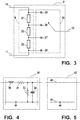
- FIG. 3 shows the front end 8 in more detail.
- the front end 8 comprises the phase shifter 9 between the first input 10 and the second input 11 capable of shifting the phase of a first signal traveling through the phase shifter 9 from the first input 10 to the second input 11 by a predetermined phase shift and capable of shifting the phase of a second signal traveling through the phase shifter 9 from the second input 11 to the first input 10 by the predetermined phase shift.
- the predetermined phase shift is 270°.
- the phase shifter 9 comprises in the current example three phase shifting elements 21, 22 and 23. Each of these phase shifting elements 21, 22 and 23 provides for a phase shift of 90°.
- the phase shifter 9 provides at a first point 25 a signal being the sum of the first signal and the second signal being delayed by 270°.
- the phase shifter 9 provides at a second point 26 a signal being the sum of the first signal being delayed by 90° and the second signal being delayed by 180°.
- the phase shifter 9 provides at a third point 27 a signal being the sum of the first signal being delayed by 180° and the second signal being delayed by 90° .
- the phase shifter 9 provides at a fourth point 28 a signal being the sum of the first signal being delayed by 270° and the second signal.
- the front end 8 further comprises the selector 20 for selecting a signal of one of the points 25, 26, 27 or 28 and for providing it as an output signal at the output 12.
- FIG. 4 shows a preferred embodiment of a phase shifting element 35 which can be used as phase shifting element 21, 22 and/or 23.
- the phase shifting element 35 comprises an inductive element 30, two resistors 31 and 33, and a capacitor 34.
- the ratio of the inductivity of the inductive element 30 and the capacitance of the capacitor 34 is preferably in the vicinity of 2,5.
- FIG. 5 shows a phase shifter 42 which can be used as an embodiment of the phase shifter 9 or a phase shifting element 21, 22 and/or 23.
- the phase shifter 42 comprises a transmission line 40 and a second line 41.
- Phase shifters 9 and 42 and phase shifting element 35 are preferably implemented in an integrated circuit.
- the receiver arrangement 2 in particular the front end 8 as well as the first antenna 4 and the second antenna 5 are designed to operate approximately in the frequency range of 1 through 2 GHz. They are in particular designed to operate in a frequency range of one, more, or all of the following frequency bands: GSM-900 925-960 MHz GSM1800 1805-1880 MHz GSM1900 1930-1990 MHz UMTS FDD 2110-2170 MHz UMTS TDD 2010-2025 MHz
Landscapes
- Engineering & Computer Science (AREA)
- Computer Networks & Wireless Communication (AREA)
- Signal Processing (AREA)
- Transceivers (AREA)
- Variable-Direction Aerials And Aerial Arrays (AREA)
- Mobile Radio Communication Systems (AREA)
Claims (10)
- Frontend (8) für eine Mobilkommunikationsvorrichtung (1), die ein Mobiltelefon oder Mobilcomputer insbesondere gemäß dem GSM- oder UMTS-Standard ist, wobei das Frontend mindestens zwei Eingänge, einen ersten Eingang (10) und einen zweiten Eingang (11), umfasst, mit einem Phasenschieber (9, 42), der die Phase eines von dem ersten Eingang (10) durch den Phasenschieber (9, 42) zu dem zweiten Eingang (11) verlaufenden ersten Signals um eine vorbestimmte Phasenverschiebung verschieben kann und die Phase eines von dem zweiten Eingang (11) durch den Phasenschieber (9, 42) verlaufenden zweiten Signals verschieben kann, wobei das Frontend (8) einen Selektor (20) zum Auswählen eines Ausgangssignals zwischen dem ersten Eingang (10) und dem zweiten Eingang (11) umfasst,
dadurch gekennzeichnet, dass
der Selektor (20) das Ausgangssignal so auswählen kann, dass das Ausgangssignal die Summe des um eine erste Phasenverschiebung zwischen 0 und der vorbestimmten Phasenverschiebung verzögerten ersten Signals und des um eine zweite Phasenverschiebung, die die Differenz zwischen der vorbestimmten Phasenverschiebung und der ersten Phasenverschiebung ist, verzögerten zweiten Signals ist, wobei der Phasenschieber (9, 42) mindestens zwei, insbesondere drei, Phasenverschiebungseinheiten (21, 22, 23, 35) umfasst und eine Phasenverschiebungseinheit (21, 22, 23) eine Phasenverschiebung zwischen 10° und 90° bereitstellt. - Frontend (8) nach Anspruch 1, wobei die Mobilkommunikationsvorrichtung (1) mindestens zwei Antennen, eine erste Antenne (4) und eine zweite Antenne (5), umfasst.
- Frontend (8) nach Anspruch 2, wobei die erste Antenne (4) mit dem ersten Eingang (10) des Frontend verbunden ist.
- Frontend (8) nach Anspruch 2 oder 3, wobei die zweite Antenne (5) mit dem zweiten Eingang (11) des Frontend verbunden ist.
- Frontend (8) nach einem der vorhergehenden Ansprüche, wobei der Phasenschieber (9, 42) eine Übertragungsleitung (40) umfasst.
- Frontend (8) nach einem der vorhergehenden Ansprüche, wobei das Frontend (8) als eine integrierte Schaltung implementiert ist.
- Frontend (8) nach Anspruch 1, wobei eine Phasenverschiebungseinheit (21, 22, 23, 35) eine Phasenverschiebung zwischen 10° und 90°, insbesondere eine Phasenverschiebung von 45° oder 90°, bereitstellt.
- Frontend (8) nach Anspruch 1 oder 7, wobei mindestens eine Phasenverschiebungseinheit (21, 22, 23, 35) mindestens ein induktives Element (30) und mindestens einen Kondensator (34) umfasst.
- Frontend (8) nach Anspruch 8, wobei das induktive Element (30) und der Kondensator (34) so dimensioniert sind, dass sie in einer integrierten Schaltung implementiert werden können.
- Mobilkommunikationsvorrichtung (1) mit einem Frontend (8) nach einem der vorhergehenden Ansprüche, wobei der Phasenschieber (9) drei Phasenverschiebungseinheiten (21, 22 und 23) umfasst, die jeweils eine Phasenverschiebung von 90° bereitstellen, so dass der Phasenschieber (9) an einem ersten Punkt (25) ein Signal bereitstellt, bei dem es sich um die Summe des ersten Signals und des zweiten Signals, das um 270° verzögert ist, handelt, der Phasenschieber (9) an einem zweiten Punkt (26) ein Signal bereitstellt, bei dem es sich um die Summe des ersten Signals, das um 90° verzögert ist, und des zweiten Signals, das um 180° verzögert ist, handelt, der Phasenschieber (9) an einem dritten Punkt (27) ein Signal bereitstellt, bei dem es sich um die Summe des ersten Signals, das um 180° verzögert ist, und des zweiten Signals, das um 90° verzögert ist, handelt, und der Phasenschieber (9) an einem vierten Punkt (28) ein Signal bereitstellt, bei dem es sich um die Summe des ersten Signals, das um 270° verzögert ist, und des zweiten Signals handelt.
Priority Applications (2)
| Application Number | Priority Date | Filing Date | Title |
|---|---|---|---|
| DK10154412.0T DK2190132T3 (en) | 2000-08-09 | 2000-08-09 | Front end of a mobile communication device |
| EP10154412.0A EP2190132B1 (de) | 2000-08-09 | 2000-08-09 | Frontend für ein mobiles Kommunikationsgerät |
Applications Claiming Priority (2)
| Application Number | Priority Date | Filing Date | Title |
|---|---|---|---|
| EP00117043.0A EP1179894B2 (de) | 2000-08-09 | 2000-08-09 | Frontend für ein mobiles Kommunikationsgerät |
| EP10154412.0A EP2190132B1 (de) | 2000-08-09 | 2000-08-09 | Frontend für ein mobiles Kommunikationsgerät |
Related Parent Applications (3)
| Application Number | Title | Priority Date | Filing Date |
|---|---|---|---|
| EP00117043.0 Division | 2000-08-09 | ||
| EP00117043.0A Division EP1179894B2 (de) | 2000-08-09 | 2000-08-09 | Frontend für ein mobiles Kommunikationsgerät |
| EP00117043.0A Division-Into EP1179894B2 (de) | 2000-08-09 | 2000-08-09 | Frontend für ein mobiles Kommunikationsgerät |
Publications (3)
| Publication Number | Publication Date |
|---|---|
| EP2190132A2 EP2190132A2 (de) | 2010-05-26 |
| EP2190132A3 EP2190132A3 (de) | 2010-06-09 |
| EP2190132B1 true EP2190132B1 (de) | 2017-03-08 |
Family
ID=8169471
Family Applications (2)
| Application Number | Title | Priority Date | Filing Date |
|---|---|---|---|
| EP00117043.0A Expired - Lifetime EP1179894B2 (de) | 2000-08-09 | 2000-08-09 | Frontend für ein mobiles Kommunikationsgerät |
| EP10154412.0A Expired - Lifetime EP2190132B1 (de) | 2000-08-09 | 2000-08-09 | Frontend für ein mobiles Kommunikationsgerät |
Family Applications Before (1)
| Application Number | Title | Priority Date | Filing Date |
|---|---|---|---|
| EP00117043.0A Expired - Lifetime EP1179894B2 (de) | 2000-08-09 | 2000-08-09 | Frontend für ein mobiles Kommunikationsgerät |
Country Status (3)
| Country | Link |
|---|---|
| EP (2) | EP1179894B2 (de) |
| DE (1) | DE60043885D1 (de) |
| DK (2) | DK1179894T4 (de) |
Family Cites Families (6)
| Publication number | Priority date | Publication date | Assignee | Title |
|---|---|---|---|---|
| US3295138A (en) † | 1963-10-31 | 1966-12-27 | Sylvania Electric Prod | Phased array system |
| US5280637A (en) * | 1991-09-18 | 1994-01-18 | Motorola, Inc. | Phase combining method and apparatus for use in a diversity receiver |
| JPH0621711A (ja) * | 1992-06-30 | 1994-01-28 | Sumitomo Chem Co Ltd | 自動車用アンテナ装置 |
| US5504745A (en) † | 1994-06-01 | 1996-04-02 | Agence Spatiale Europeenne | Switching cell transmission device employing dual gate FET's as one-way RF switching element |
| EP0728372A1 (de) † | 1994-09-14 | 1996-08-28 | Koninklijke Philips Electronics N.V. | Funkübertragungssystem und funkgerät zur anwendung darin |
| EP1014480A3 (de) * | 1998-12-17 | 2001-12-05 | Ntt Mobile Communications Network Inc. | Funkempfänger mit hoher Empfindlichkeit |
-
2000
- 2000-08-09 DK DK00117043.0T patent/DK1179894T4/da active
- 2000-08-09 DK DK10154412.0T patent/DK2190132T3/en active
- 2000-08-09 EP EP00117043.0A patent/EP1179894B2/de not_active Expired - Lifetime
- 2000-08-09 EP EP10154412.0A patent/EP2190132B1/de not_active Expired - Lifetime
- 2000-08-09 DE DE60043885T patent/DE60043885D1/de not_active Expired - Lifetime
Non-Patent Citations (1)
| Title |
|---|
| None * |
Also Published As
| Publication number | Publication date |
|---|---|
| EP1179894B1 (de) | 2010-02-24 |
| EP1179894B2 (de) | 2020-01-15 |
| EP2190132A2 (de) | 2010-05-26 |
| DE60043885D1 (de) | 2010-04-08 |
| DK1179894T3 (da) | 2010-05-17 |
| DK1179894T4 (da) | 2020-04-14 |
| EP1179894A1 (de) | 2002-02-13 |
| EP2190132A3 (de) | 2010-06-09 |
| DK2190132T3 (en) | 2017-06-06 |
Similar Documents
| Publication | Publication Date | Title |
|---|---|---|
| US7116952B2 (en) | Method and apparatus to provide an area efficient antenna diversity receiver | |
| US5926751A (en) | Method and apparatus for receiving communication signals | |
| KR0158785B1 (ko) | 무선통신장치 | |
| US6983132B2 (en) | Multi-band RF receiving method and apparatus in mobile communication system | |
| JP3100111B2 (ja) | 移動無線機のマルチバンド高周波回路 | |
| US6667723B2 (en) | System and method for a GPS enabled antenna | |
| US7542727B2 (en) | Method for receiving a signal on a single multi-band antenna | |
| JP3183812B2 (ja) | 移動無線機のマルチバンド高周波回路 | |
| WO2000003491A1 (en) | Configurable single and dual vcos for dual- and tri-band wireless communication systems | |
| WO2004095623A1 (en) | A frequency-selective device and method thereof for reception/transmission of communication signals in a wireless multi-band device | |
| JP2007019939A (ja) | 無線通信装置及びそれを用いた携帯電話端末 | |
| WO2000019629A1 (en) | Using a single low-noise amplifier in a multi-band wireless station | |
| WO2002091569A1 (en) | Gain adjusting and circuit arrangement | |
| EP2134000B1 (de) | Multiband-Mobilkommunikationsgerät | |
| US20080139240A1 (en) | Communication device capable of operating in a plurality of communications systems | |
| US7162266B2 (en) | Multiple band handset architecture | |
| EP2190132B1 (de) | Frontend für ein mobiles Kommunikationsgerät | |
| EP1705747A1 (de) | Mehrbandantenne zur Verwendung in einem mobilen Funkgerät | |
| EP0758821B1 (de) | Empfangsschaltung für ein tragbares Telefon | |
| KR100312822B1 (ko) | 통화공간의 커버리지 확대를 위한 rf 지연장치 | |
| CN119602813A (zh) | 射频PA Mid器件、射频系统和电子设备 | |
| KR20050108287A (ko) | 멀티밴드 멀티모드 기능을 가진 휴대용 단말기의 고주파송수신 장치 및 이를 구비한 휴대용 단말기 | |
| KR20000067785A (ko) | 섹터 병합을 위한 기지국 장치 및 그의 송수신 방법 | |
| MXPA98001327A (es) | Metodo y aparato para recibir señales decomunicacion |
Legal Events
| Date | Code | Title | Description |
|---|---|---|---|
| PUAI | Public reference made under article 153(3) epc to a published international application that has entered the european phase |
Free format text: ORIGINAL CODE: 0009012 |
|
| PUAL | Search report despatched |
Free format text: ORIGINAL CODE: 0009013 |
|
| AC | Divisional application: reference to earlier application |
Ref document number: 1179894 Country of ref document: EP Kind code of ref document: P |
|
| AK | Designated contracting states |
Kind code of ref document: A2 Designated state(s): DE DK FR GB IT |
|
| AX | Request for extension of the european patent |
Extension state: AL LT LV MK RO SI |
|
| AK | Designated contracting states |
Kind code of ref document: A3 Designated state(s): DE DK FR GB IT |
|
| AX | Request for extension of the european patent |
Extension state: AL LT LV MK RO SI |
|
| 17P | Request for examination filed |
Effective date: 20101202 |
|
| 17Q | First examination report despatched |
Effective date: 20120206 |
|
| GRAP | Despatch of communication of intention to grant a patent |
Free format text: ORIGINAL CODE: EPIDOSNIGR1 |
|
| RIC1 | Information provided on ipc code assigned before grant |
Ipc: H01Q 3/36 20060101ALI20160818BHEP Ipc: H04B 7/08 20060101AFI20160818BHEP |
|
| INTG | Intention to grant announced |
Effective date: 20160922 |
|
| RIN1 | Information on inventor provided before grant (corrected) |
Inventor name: PEDERSEN, GERT FROLUND Inventor name: KNUDSEN, MIKAEL B. |
|
| STAA | Information on the status of an ep patent application or granted ep patent |
Free format text: STATUS: GRANT OF PATENT IS INTENDED |
|
| GRAS | Grant fee paid |
Free format text: ORIGINAL CODE: EPIDOSNIGR3 |
|
| GRAA | (expected) grant |
Free format text: ORIGINAL CODE: 0009210 |
|
| STAA | Information on the status of an ep patent application or granted ep patent |
Free format text: STATUS: THE PATENT HAS BEEN GRANTED |
|
| AC | Divisional application: reference to earlier application |
Ref document number: 1179894 Country of ref document: EP Kind code of ref document: P |
|
| AK | Designated contracting states |
Kind code of ref document: B1 Designated state(s): DE DK FR GB IT |
|
| REG | Reference to a national code |
Ref country code: GB Ref legal event code: FG4D |
|
| REG | Reference to a national code |
Ref country code: DE Ref legal event code: R096 Ref document number: 60049576 Country of ref document: DE |
|
| REG | Reference to a national code |
Ref country code: DK Ref legal event code: T3 Effective date: 20170601 |
|
| REG | Reference to a national code |
Ref country code: FR Ref legal event code: PLFP Year of fee payment: 18 |
|
| REG | Reference to a national code |
Ref country code: DE Ref legal event code: R097 Ref document number: 60049576 Country of ref document: DE |
|
| PLBE | No opposition filed within time limit |
Free format text: ORIGINAL CODE: 0009261 |
|
| STAA | Information on the status of an ep patent application or granted ep patent |
Free format text: STATUS: NO OPPOSITION FILED WITHIN TIME LIMIT |
|
| 26N | No opposition filed |
Effective date: 20171211 |
|
| REG | Reference to a national code |
Ref country code: FR Ref legal event code: PLFP Year of fee payment: 19 |
|
| PGFP | Annual fee paid to national office [announced via postgrant information from national office to epo] |
Ref country code: IT Payment date: 20190821 Year of fee payment: 20 Ref country code: DK Payment date: 20190822 Year of fee payment: 20 Ref country code: FR Payment date: 20190822 Year of fee payment: 20 |
|
| PGFP | Annual fee paid to national office [announced via postgrant information from national office to epo] |
Ref country code: GB Payment date: 20190827 Year of fee payment: 20 |
|
| PGFP | Annual fee paid to national office [announced via postgrant information from national office to epo] |
Ref country code: DE Payment date: 20191030 Year of fee payment: 20 |
|
| REG | Reference to a national code |
Ref country code: DE Ref legal event code: R071 Ref document number: 60049576 Country of ref document: DE |
|
| REG | Reference to a national code |
Ref country code: DK Ref legal event code: EUP Expiry date: 20200809 |
|
| REG | Reference to a national code |
Ref country code: GB Ref legal event code: PE20 Expiry date: 20200808 |
|
| PG25 | Lapsed in a contracting state [announced via postgrant information from national office to epo] |
Ref country code: GB Free format text: LAPSE BECAUSE OF EXPIRATION OF PROTECTION Effective date: 20200808 |