EP2190218B1 - Filterbanksystem mit spezifischen Sperrdämpfungsanteilen für eine Hörvorrichtung - Google Patents
Filterbanksystem mit spezifischen Sperrdämpfungsanteilen für eine Hörvorrichtung Download PDFInfo
- Publication number
- EP2190218B1 EP2190218B1 EP09175081.0A EP09175081A EP2190218B1 EP 2190218 B1 EP2190218 B1 EP 2190218B1 EP 09175081 A EP09175081 A EP 09175081A EP 2190218 B1 EP2190218 B1 EP 2190218B1
- Authority
- EP
- European Patent Office
- Prior art keywords
- filter bank
- attenuation
- frequency
- synthesis
- dependent
- Prior art date
- Legal status (The legal status is an assumption and is not a legal conclusion. Google has not performed a legal analysis and makes no representation as to the accuracy of the status listed.)
- Active
Links
Images
Classifications
-
- H—ELECTRICITY
- H04—ELECTRIC COMMUNICATION TECHNIQUE
- H04R—LOUDSPEAKERS, MICROPHONES, GRAMOPHONE PICK-UPS OR LIKE ACOUSTIC ELECTROMECHANICAL TRANSDUCERS; ELECTRIC HEARING AIDS; PUBLIC ADDRESS SYSTEMS
- H04R25/00—Electric hearing aids
- H04R25/50—Customised settings for obtaining desired overall acoustical characteristics
- H04R25/505—Customised settings for obtaining desired overall acoustical characteristics using digital signal processing
-
- H—ELECTRICITY
- H04—ELECTRIC COMMUNICATION TECHNIQUE
- H04R—LOUDSPEAKERS, MICROPHONES, GRAMOPHONE PICK-UPS OR LIKE ACOUSTIC ELECTROMECHANICAL TRANSDUCERS; ELECTRIC HEARING AIDS; PUBLIC ADDRESS SYSTEMS
- H04R2430/00—Signal processing covered by H04R, not provided for in its groups
- H04R2430/03—Synergistic effects of band splitting and sub-band processing
Definitions
- the present invention relates to a filter bank system for a hearing apparatus having an analysis filter bank for decomposing an input signal into subband signals, processing means for manipulating at least one of the subband signals and a synthesis filter bank for composing the manipulated subband signal with at least one other of the subband signals.
- the present invention relates to a hearing aid with such a filter bank system.
- hearing device is understood to mean here any sound-emitting device that can be worn in or on the ear or on the head, in particular a hearing device, a headset, headphones and the like.
- Hearing aids are portable hearing aids that are used to care for the hearing impaired.
- different types of hearing aids such as behind-the-ear hearing aids (BTE), hearing aid with external receiver (RIC: receiver in the canal) and in-the-ear hearing aids (IDO), e.g. Concha hearing aids or canal hearing aids (ITE, CIC).
- BTE behind-the-ear hearing aids
- RIC hearing aid with external receiver
- IDO in-the-ear hearing aids
- ITE canal hearing aids
- the hearing aids listed by way of example are worn on the outer ear or in the ear canal.
- bone conduction hearing aids, implantable or vibrotactile hearing aids are also available on the market. The stimulation of the damaged hearing takes place either mechanically or electrically.
- Hearing aids have in principle as essential components an input transducer, an amplifier and an output transducer.
- the input transducer is usually a sound receiver, z. As a microphone, and / or an electromagnetic receiver, for. B. an induction coil.
- the output transducer is usually used as an electroacoustic transducer, z. As miniature speaker, or as an electromechanical transducer, z. B. bone conduction, realized.
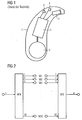
- the amplifier is usually integrated in a signal processing unit. This basic structure is in FIG. 1 shown using the example of a behind-the-ear hearing aid. In a hearing aid housing 1 for carrying behind the ear, one or more microphones 2 for receiving the sound from the environment are installed.
- a signal processing unit 3 which is also integrated in the hearing aid housing 1, processes the microphone signals and amplifies them.
- the output signal of the signal processing unit 3 is transmitted to a loudspeaker or earpiece 4, which outputs an acoustic signal.
- the sound is optionally transmitted via a sound tube, which is fixed with an earmold in the ear canal, to the eardrum of the device carrier.
- the power supply of the hearing device and in particular the signal processing unit 3 is effected by a likewise integrated into the hearing aid housing 1 battery. 5
- Sound signals which are recorded by one or more microphones of a hearing device or another hearing device are usually decomposed into subband signals for further processing.
- an analysis-synthesis filter bank system This has one or more frequency-selective digital analysis filter banks (AFB), with which the sound signal is decomposed into K> 1 subband signals.
- AFB frequency-selective digital analysis filter banks
- Subband-specific signal manipulation then takes place, in particular amplification or attenuation of the subband signals.
- a re-synthesis of the manipulated subband signals is performed by means of one or more digital synthesis filter banks (SFB).
- the filter bank system is usually oversampling and has an oversampling factor U ⁇ 1.
- High-quality filter banks in hearing aids are subject to certain requirements. For example, in the bottommost bands, a channel width of at least about 250 Hz is needed. Otherwise, the band gap should be based on the Bark scale. A finer resolution, for example in the broader bands according to the Bark scale, is the application but not contrary. Furthermore, a channel number of at least 22 is desirable. Disturbance due to aliasing and imaging should be below about 40-60 dB, depending on the application (hearing impairment of the patient). Due to the intensive subband processing (especially the high gain required to compensate for hearing loss) in hearing aids, conventional methods for erasing aliasing and imaging are not effective. The filter banks are therefore fundamentally "non-critical" to scan.
- the group delay (in each case for AFB and SFB) should be well below 5 ms and the group delay distortions should not exceed a certain range. Especially for high frequencies, the group delay is to be kept as low as possible, which represents a significant limiting factor for the filter bank.
- the AFB and the SFB should be designed such that the signal / interference distance at the output of the filter bank system with arbitrary manipulation (amplification / attenuation) of the subband signals changed only within predeterminable limits. This also includes the case of the complete independence of the signal / interference distance at the output of the filter bank system from the manipulation of the subband signals.
- the AFB and the SFB should be designed so that for a at the output of the filter bank system in response to the manipulation of the subband signals permissible variation of the signal / interference distance of the circuit complexity (corresponds to the filter orders) and / or the group delay (total delay ) of the filter bank system is reduced over the prior art.
- the document 698 33 749 T2 describes a filter bank analysis structure for a hearing aid in which a buffer is connected to a multiplication unit so that the buffer values can be multiplied by a window function representing a prototype low-pass filter of a fast Fourier transform procedure.
- a window function representing a prototype low-pass filter of a fast Fourier transform procedure.
- filter banks AFB and SFB have been designed the same (in particular, equal magnitude specification of minimum phase AFB and maximum phase SFB).
- the oversampling factor was not considered in detail.
- the signal manipulation was not considered in the system specification of the filter bank system. This resulted in large fluctuations in the signal quality (signal / interference distance) as a function of the respective manipulation (amplification) of the subband signals.
- the object of the present invention is thus to propose a filter bank system with reduced computational effort, with which nevertheless a high signal quality, in particular a specific signal / interference distance, can be achieved.
- AZA analysis filter bank
- SFB synthesis filter bank
- all the attenuation components are configured on the basis of the signal / interference distance at the output of the filter bank system.
- the expert is given a simple criterion in the design of the filter bank systems at hand.
- the analysis baseline attenuation fraction depends on the downsampling factor of the analysis filter bank.
- the basic attenuation can be set to a minimum value.
- a masking effect of a human ear can be taken into account in the frequency-dependent analysis-attenuation component and / or synthesis-attenuation component. This makes use of the fact that, in the case of sound perception, two parts located close to one another in a spectrally obscure manner may be completely or partially obscured. Noise components which are obscured by other components would thus no longer have to be fully attenuated.
- the frequency-dependent analysis-attenuation component may be periodically modified, the periodicity being determined by the oversampling factor of the analysis filter bank (AFB) and the maximum attenuation reduction by the passbands (transmission behavior) of the AFB and SFB.
- the frequency-dependent synthesis damping component can be periodically modified, the periodicity also being determined by the upward-scaling factor or integration factor of the synthesis filter bank and the maximum attenuation reduction by the oversampling factor.
- the periodicity of the attenuation components takes into account the fact that the artefacts also occur periodically through aliasing and imaging.
- baseline synthesis fraction of synthesis may depend on the synthesis filter bank up-down factor.
- the frequency-dependent first synthesis damping component depends on a gain of the processing device.
- the attenuation of the interference components can just be chosen so that only then strongly attenuated if they are also high due to high amplification of the useful signal. This, too, can generally or temporarily reduce the filter effort.
- the periodicity is determined by the oversampling factor of the synthesis filter bank (SFB) and the maximum attenuation reduction by the transmission range (transmission behavior) of the SFB.
- FIG. 2 a filter bank system is shown schematically, as it is used for example in a device.
- An input signal e eg, speech signal
- AFB analysis filter bank
- M1, M2, M3,..., M32 of the individual signals is followed by a subband-specific manipulation M1, M2, M3,..., M32 of the individual signals.
- the individual subband signals are synthesized in an adjusted with respect to the amount of frequency response to the analysis filter bank AFB synthesis filter bank SFB again to an output signal a.
- the individual filter functions are implemented by so-called prototype filters, from which the individual filters are derived, for example, by a complex-modulating transformation kernel in the filter bank.
- prototype filters have, for example, low-pass characteristics. In the following, only the blocking area of the prototype filter is considered.
- the notch attenuation specification of the transfer functions of the AFB is composed of a frequency-independent basic attenuation a AFB and frequency-dependent attenuation components.
- the blocking attenuation specification of the transfer functions of the SFB is composed of a frequency-independent basic attenuation a SFB and first and second frequency-dependent attenuation components, wherein the first frequency-dependent attenuation component additionally depends on the signal manipulation between the two filter banks.
- U oversampling factor
- mutual masking effects of frequency closely adjacent signal components are to be used in order to reduce the circuit complexity or the filter order and / or the total group delay of the filter bank system.
- the deterioration of the signal / interference distance at the output of the filter bank system should be approximately the same for any manipulation (amplification / attenuation of the subband signals by aliasing contributions of the AFB or by imaging contributions of the SFB.
- the configuration of a concrete filter bank system will now be described on the basis of FIG. 3 and 4 explained in more detail.
- the signal / interference distance SNR is generally used at the output of the filter bank system.
- a frequency independent attenuation a basic AFB is first determined by the desired SNR AFB.
- This signal / interference distance SNR AFB results from aliasing in the AFB.
- M decimation factor
- the basic attenuation in the stopband is now supplemented by a frequency-dependent additional stop attenuation.
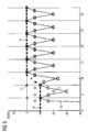
- a first part 10 of the frequency-dependent attenuation component of the AFB specification results from the fact that masking effects of the human ear are utilized. This reduces the stopband attenuation near the filter passband. In the example of FIG. 3 this second part 10 is reduced by 10 dB in the vicinity of the passband and then ramps up from the eighth subband to its final value.
- a second part 11 of the frequency-dependent damping component of the AFB specification results from the fact that the interference components generated in the AFB by aliasing are evaluated differently in the SFB.
- the second part 11 is periodic so that the total stopband attenuation over the frequency is periodically modified.
- the number of periods depends on the oversampling factor U, and the depth of the allowable attenuation reduction is determined by the product of the passbands of the prototype filters in the AFB and SFB.
- the total stop attenuation 12 results from the sum of all attenuation components including the fundamental attenuation, based on a logarithmic measure (decibel).
- a logarithmic measure decibel
- FIG. 3 the entire frequency-dependent stopband attenuation 12 is shown. Their absolute level results from the basic attenuation a AFB (in FIG. 3 not shown), which is added in the logarithmic measure to the frequency-dependent stopband attenuation.
- the frequency-dependent stop attenuation thus increases over the 32 subbands selected here according to the ramp of the first part 10.
- the basic attenuation a SFB of the synthesis filter bank is likewise defined by the desired signal / interference distance SNRS FB . It results from imaging in the SFB. Again, the fundamental attenuation a SFB is dependent on the interpolation factor M of the SFB, which is equal to the decimation factor M of the AFB.
- This gain-dependent component is important because the imaging components in the SFB are also enhanced.
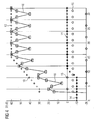
- a first part 14 of the second frequency-dependent damping component of the SFB specification results, as in the AFB, in exploiting masking effects of the human ear.
- the specification of the stop band attenuation of the transfer function of the SFB filters in the vicinity of the filter pass band is reduced exactly as in the AFB. This reduction can also contribute to a reduction of the filter order.
- a second part 15 of the second frequency-dependent damping component of the SFB specification results from the fact that U • (M-1) spectral components (images of the SFB) of different strengths come to lie in each channel.
- M-1 main components central region of a spectral distribution of signal and alias power
- KM-1 differentially attenuated secondary components outer regions of the spectral distribution of signal and alias power.
- the specification of the stopband attenuation is thus modified periodically over the frequency, the number of the periods is dependent on the oversampling factor U and the depth of the permissible attenuation reduction is determined by the passband of the prototype filter (in the SFB).
- the total stop attenuation 16 of the prototype filter for the SFB again results from the sum of all attenuation components.
- the fundamental attenuation a SFB determines the absolute position of the stopband attenuation by adding it for the specification of the prototype filter to the frequency-dependent attenuation parts in the logarithmic sense.
- the frequency-dependent reduction of the stopband attenuation 12 and 16 in the optimized specifications is now used to reduce, for example, the circuit complexity and the filter order.
- the frequency-dependent reduction of the stopband attenuation can also be used to reduce the group delay.
- the frequency-independent basic attenuation of the filter banks can be increased if the stopband attenuation can be reduced in a frequency-dependent manner.
Landscapes
- Health & Medical Sciences (AREA)
- General Health & Medical Sciences (AREA)
- Neurosurgery (AREA)
- Otolaryngology (AREA)
- Physics & Mathematics (AREA)
- Engineering & Computer Science (AREA)
- Acoustics & Sound (AREA)
- Signal Processing (AREA)
- Circuit For Audible Band Transducer (AREA)
- Networks Using Active Elements (AREA)
- Filters That Use Time-Delay Elements (AREA)
Description
- Die vorliegende Erfindung betrifft ein Filterbanksystem für eine Hörvorrichtung mit einer Analysefilterbank zum Zerlegen eines Eingangssignals in Teilbandsignale, einer Verarbeitungseinrichtung zum Manipulieren mindestens eines der Teilbandsignale und einer Synthesefilterbank zum Zusammensetzen des manipulierten Teilbandsignals mit mindestens einem weiteren der Teilbandsignale. Darüber hinaus betrifft die vorliegende Erfindung ein Hörgerät mit einem derartigen Filterbank-system. Unter dem Begriff "Hörvorrichtung" wird hier jedes im oder am Ohr bzw. am Kopf tragbare schallausgebende Gerät verstanden, insbesondere ein Hörgerät, ein Headset, Kopfhörer und dergleichen.
- Hörgeräte sind tragbare Hörvorrichtungen, die zur Versorgung von Schwerhörenden dienen. Um den zahlreichen individuellen Bedürfnissen entgegenzukommen, werden unterschiedliche Bauformen von Hörgeräten wie Hinter-dem-Ohr-Hörgeräte (HdO), Hörgerät mit externem Hörer (RIC: receiver in the canal) und In-dem-Ohr-Hörgeräte (IdO), z.B. auch Concha-Hörgeräte oder Kanal-Hörgeräte (ITE, CIC), bereitgestellt. Die beispielhaft aufgeführten Hörgeräte werden am Außenohr oder im Gehörgang getragen. Darüber hinaus stehen auf dem Markt aber auch Knochenleitungshörhilfen, implantierbare oder vibrotaktile Hörhilfen zur Verfügung. Dabei erfolgt die Stimulation des geschädigten Gehörs entweder mechanisch oder elektrisch.
- Hörgeräte besitzen prinzipiell als wesentliche Komponenten einen Eingangswandler, einen Verstärker und einen Ausgangswandler. Der Eingangswandler ist in der Regel ein Schallempfänger, z. B. ein Mikrofon, und/oder ein elektromagnetischer Empfänger, z. B. eine Induktionsspule. Der Ausgangswandler ist meist als elektroakustischer Wandler, z. B. Miniaturlautsprecher, oder als elektromechanischer Wandler, z. B. Knochenleitungshörer, realisiert. Der Verstärker ist üblicherweise in eine Signalverarbeitungseinheit integriert. Dieser prinzipielle Aufbau ist in
FIG 1 am Beispiel eines Hinter-dem-Ohr-Hörgeräts dargestellt. In ein Hörgerätegehäuse 1 zum Tragen hinter dem Ohr sind ein oder mehrere Mikrofone 2 zur Aufnahme des Schalls aus der Umgebung eingebaut. Eine Signalverarbeitungseinheit 3, die ebenfalls in das Hörgerätegehäuse 1 integriert ist, verarbeitet die Mikrofonsignale und verstärkt sie. Das Ausgangssignal der Signalverarbeitungseinheit 3 wird an einen Lautsprecher bzw. Hörer 4 übertragen, der ein akustisches Signal ausgibt. Der Schall wird gegebenenfalls über einen Schallschlauch, der mit einer Otoplastik im Gehörgang fixiert ist, zum Trommelfell des Geräteträgers übertragen. Die Energieversorgung des Hörgeräts und insbesondere die der Signalverarbeitungseinheit 3 erfolgt durch eine ebenfalls ins Hörgerätegehäuse 1 integrierte Batterie 5. - Schallsignale, die von einem oder mehreren Mikrofonen eines Hörgeräts bzw. einer anderen Hörvorrichtung aufgenommen werden, werden üblicherweise zur weiteren Verarbeitung in Teilbandsignale zerlegt. Hierzu bedient man sich üblicherweise eines Analyse-Synthese-Filterbanksystems. Dieses besitzt eine oder mehrere frequenzselektive digitale Analyse-Filterbänke (AFB), mit denen das Schallsignal in K > 1 Teilbandsignale zerlegt wird. Anschließend erfolgt eine teilbandspezifische Signalmanipulation, insbesondere eine Verstärkung bzw. Abschwächung der Teilbandsignale. Anschließend wird eine Re-Synthese der manipulierten Teilbandsignale mittels einer oder mehrerer digitaler Synthese-Filterbänke (SFB) durchgeführt. Das Filterbank-System ist in der Regel überabtastend und besitzt einen Überabtastfaktor U ≥ 1.
- An hochwertige Filterbänke in Hörgeräten werden gewisse Anforderungen gestellt. So wird beispielsweise in den untersten Bändern eine Kanalbreite von mindestens etwa 250 Hz benötigt. Ansonsten sollte sich der Bandabstand in etwa nach der Bark-Skala richten. Eine feinere Auflösung, beispielsweise in den breiteren Bändern nach der Bark-Skala, steht der Anwendung jedoch nicht entgegen. Ferner ist eine Kanalzahl von mindestens 22 wünschenswert. Störanteile durch Aliasing und Imaging sollten je nach Anwendungsfall (Hörschaden des Patienten) unterhalb von etwa 40-60 dB liegen. Aufgrund der intensiven Teilbandverarbeitung (insbesondere die hohe erforderliche Verstärkung zur Kompensation des Hörschadens) bei Hörgeräten sind herkömmliche Verfahren zur Auslöschung von Aliasing und Imaging nicht wirksam. Die Filterbänke sind daher grundsätzlich "nicht kritisch" abzutasten. Des Weiteren sollte die Gruppenlaufzeit (jeweils für AFB und SFB) deutlich unter 5 ms liegen und die Gruppenlaufzeitverzerrungen einen gewissen Rahmen nicht überschreiten. Insbesondere für hohe Frequenzen ist dabei die Gruppenlaufzeit so gering wie möglich zu halten, was einen wesentlichen limitierenden Faktor für die Filterbank darstellt.
- Speziell sollten die AFB und die SFB derart ausgebildet sein, dass sich der Signal/Stör-Abstand am Ausgang des Filterbank-Systems bei beliebiger Manipulation (Verstärkung/Abschwächung) der Teilbandsignale nur innerhalb vorgebbarer Grenzen verändert. Darin eingeschlossen ist auch der Fall der gänzlichen Unabhängigkeit des Signal/Stör-Abstands am Ausgang des Filterbanksystems von der Manipulation der Teilbandsignale.
- Darüber hinaus sollten die AFB und die SFB derart ausgelegt sein, dass für eine am Ausgang des Filterbank-Systems in Abhängigkeit von der Manipulation der Teilbandsignale zulässige Schwankung des Signal/Stör-Abstands der Schaltungsaufwand (entspricht den Filterordnungen) und/oder die Gruppenlaufzeit (Gesamtverzögerung) des Filterbanksystems gegenüber dem Stand der Technik vermindert ist.
- In dem Dokument 698 33 749 T2 ist eine Filterbankanalysestruktur für ein Hörhilfegerät beschrieben, bei welcher ein Puffer mit einer Multiplikationseinheit verbunden ist, so dass die Pufferwerte mit einer Fensterfunktion multipliziert werden können, welche einen Prototyp-Tiefpassfilter einer schnellen Fourier-Transformationsprozedur darstellt. In diesem Zusammenhang wird dem Fachmann gelehrt, dass es notwendig ist, diese Funktion korrekt zu entwerfen, um den Filterbändern eine gewünschte Bandpass- und Stoppbandreaktion zu geben und damit die hörbare Verfälschungsstörung zu vermindern.
- Bei bisherigen Ansätzen zur Lösung dieser Problematiken wurden die Filterbänke AFB und SFB beispielsweise gleich entworfen (insbesondere gleiche Betragsspezifikation von minimalphasiger AFB und maximalphasiger SFB). Bei der frequenzunabhängigen Sperrdämpfung wurde der Überabtastfaktor nicht im Detail berücksichtigt. Ebenso wenig wurde die Signalmanipulation bei der Systemspezifikation des Filterbanksystems berücksichtigt. Damit ergaben sich große Schwankungen der Signalqualität (Signal/Stör-Abstand) in Abhängigkeit von der jeweiligen Manipulation (Verstärkung) der Teilbandsignale.
- Die Aufgabe der vorliegenden Erfindung besteht somit darin, ein Filterbanksystem mit vermindertem Rechenaufwand vorzuschlagen, mit dem dennoch eine hohe Signalqualität, insbesondere ein bestimmter Signal/Stör-Abstand, erreicht werden kann.
- Erfindungsgemäß wird diese Aufgabe gelöst durch ein Filterbanksystem für eine Hörvorrichtung mit einer Analysefilterbank (AFB) zum Zerlegen eines Eingangssignals in Teilbandsignale, einer Verarbeitungseinrichtung zum Manipulieren mindestens eines der Teilbandsignale und einer Synthesefilterbank (SFB) zum Zusammensetzen des manipulierten Teilbandsignals mit mindestens einem weiteren der Teilbandsignale, wobei die Sperrdämpfung mindestens einer der Übertragungsfunktionen der Analysefilterbank (AFB) sich zusammensetzt aus einem separat konfigurierbaren, frequenzunabhängigen Analyse-Grunddämpfungsanteil und einem separat konfigurierbaren, frequenzabhängigen Analyse-Dämpfungsanteil, und/oder die Sperrdämpfung mindestens einer der Übertragungsfunktionen der Synthesefilterbank (SFB) sich zusammensetzt aus einem separat konfigurierbaren, frequenzunabhängigen Synthese-Grunddämpfungsanteil, einem separat konfigurierbaren, frequenzabhängigen und von dem Manipulieren abhängigen, ersten Synthese-Dämpfungsteil und einem separat konfigurierbaren, frequenzabhängigen, zweiten Synthese-Dämpfungsanteil.
- In vorteilhafter Weise ist es somit möglich, bei der Sperrdämpfung bestimmte Effekte auszunutzen und die Dämpfung nur dort hochzuhalten, wo es notwendig ist. Dadurch kann die Filterordnung unter Umständen deutlich reduziert werden.
- Vorzugsweise sind sämtliche Dämpfungsanteile anhand des Signal/Stör-Abstands am Ausgang des Filterbanksystems konfiguriert. Damit ist dem Fachmann ein einfaches Kriterium beim Entwurf der Filterbanksysteme an die Hand gegeben.
- In einer speziellen Ausführungsform hängt der Analyse-Grunddämpfungsanteil von dem Abwärtstastfaktor der Analysefilterbank ab. Somit lässt sich die Grunddämpfung auf einen minimalen Wert festlegen.
- Darüber hinaus kann in dem frequenzabhängigen Analyse-Dämpfungsanteil und/oder Synthese-Dämpfungsanteil ein Maskierungseffekt eines menschlichen Gehörs berücksichtigt werden. Damit wird die Tatsache genutzt, dass bei der Schallwahrnehmung zwei spektral nahe beieinanderliegende Anteile sich unter Umständen ganz oder teilweise verdecken. Rauschanteile, die durch andere Anteile verdeckt werden, müssten somit nicht mehr in vollem Maße gedämpft werden.
- In einer weiteren Ausführungsform kann der frequenzabhängige Analyse-Dämpfungsanteil periodisch modifiziert sein, wobei die Periodizität durch den Überabtastfaktor der Analysefilterbank (AFB) und die maximale Dämpfungsabsenkung durch die Durchlassbereiche (Übertragungsverhalten) der AFB und SFB bestimmt ist. In gleicher Weise kann der frequenzabhängige Synthese-Dämpfungsanteil periodisch modifiziert sein, wobei auch hier die Periodizität von dem Aufwärtstastfaktor bzw. Integrationsfaktor der Synthesefilterbank und die maximale Dämpfungsabsenkung durch den Überabtastfaktor bestimmt ist. Durch die Periodizität der Dämpfungsanteile wird der Tatsache Rechnung getragen, dass auch die Artefakte durch Aliasing und Imaging periodisch auftreten.
- Ebenso kann der Synthese-Grunddämpfungsanteil von dem Aufwärtstastfaktor der Synthesefilterbank abhängen.
- Des Weiteren ist von besonderem Vorteil, wenn der frequenzabhängige erste Synthese-Dämpfungsanteil von einer Verstärkung der Verarbeitungseinrichtung abhängt. Damit kann die Dämpfung der Störanteile gerade so gewählt werden, dass diese nur dann stark bedämpft werden, wenn sie durch hohe Verstärkung des Nutzsignals ebenfalls hoch sind. Auch dadurch lässt sich generell bzw. temporär der Filteraufwand reduzieren.
- Ferner ist es günstig, wenn der frequenzabhängige zweite Synthese-Dämpfungsanteil periodisch modifiziert ist, die Periodizität durch den Überabtastfaktor der Synthesefilterbank (SFB) und die maximale Dämpfungsabsenkung durch den Durchlassbereich (Übertragungsverhalten) der SFB bestimmt ist.
- Es wurde bereits angedeutet, dass das oben beschriebene Filterbanksystem besonders vorteilhaft in einem Hörgerät genutzt werden kann.
- Die vorliegende Erfindung wird nun anhand der beigefügten Zeichnungen näher erläutert, in denen zeigen:
- FIG 1
- eine Prinzipskizze eines Hörgeräts gemäß dem Stand der Technik;
- FIG 2
- ein Blockschaltbild eines Filterbanksystems;
- FIG 3
- ein Beispiel für die Spezifikation eines AFB-Prototypfilters und
- FIG 4
- ein Beispiel für die Spezifikation eines SFB-Prototypfilters.
- Die nachfolgend näher geschilderten Ausführungsbeispiele stellen bevorzugte Ausführungsformen der vorliegenden Erfindung dar.
- In
FIG 2 ist ein Filterbanksystem schematisch dargestellt, wie es beispielsweise in einem Gerät genutzt wird. Ein Eingangssignal e (z. B. Sprachsignal) wird einer Analysefilterbank AFB zugeführt. Diese zerlegt das Eingangssignal e in 32 Teilbänder. Anschließend erfolgt eine teilbandspezifische Manipulation M1, M2, M3, ..., M32 der Einzelsignale. Nach der Manipulation werden die einzelnen Teilbandsignale in einer hinsichtlich des Betragsfrequenzgangs an die Analysefilterbank AFB angepasste Synthesefilterbank SFB wieder zu einem Ausgangssignal a synthetisiert. - Sowohl in der Analysefilterbank AFB als auch der Synthesefilterbank SFB werden die einzelnen Filterfunktionen durch so genannte Prototypfilter realisiert, von dem beispielsweise durch einen komplex modulierenden Transformationskern in der Filterbank die Einzelfilter abgeleitet werden. Diese Prototypfilter besitzen beispielsweise Tiefpasscharakteristik. Nachfolgend wird lediglich der Sperrbereich der Prototypfilter betrachtet.
- Entsprechend dem erfindungsgemäßen Kerngedanken setzt sich die Sperrdämpfungsspezifikation der Übertragungsfunktionen der AFB aus einer frequenzunabhängigen Grunddämpfung aAFB und frequenzabhängigen Dämpfungsanteilen zusammen. Die Sperrdämpfungsspezifikation der Übertragungsfunktionen der SFB setzt sich aus einer frequenzunabhängigen Grunddämpfung aSFB und ersten und zweiten frequenzabhängigen Dämpfungsanteilen zusammen, wobei der erste frequenzabhängige Dämpfungsanteil zusätzlich von der Signalmanipulation zwischen den beiden Filterbänken abhängt. Insbesondere soll die AFB und die SFB derart spezifiziert sein, dass durch Nutzung der Überabtastung der Teilbandsignale um einen Faktor U > 1 (U= Überabtastfaktor) der Schaltungsaufwand, d. h. die Filterordnung und/oder die Gesamtgruppenlaufzeit (Verzögerung) des Filterbanksystems vermindert ist. Außerdem sollen als Option auch wechselseitige Maskierungseffekte frequenzmäßig eng benachbarter Signalanteile genutzt werden, um den Schaltungsaufwand bzw. die Filterordnung und/oder die Gesamtgruppenlaufzeit des Filterbanksystems zu vermindern. Ferner sollte die Verschlechterung des Signal/Stör-Abstands am Ausgang des Filterbanksystems bei beliebiger Manipulation (Verstärkung/Abschwächung der Teilbandsignale durch Aliasingbeiträge der AFB bzw. durch Imagingbeiträge der SFB etwa gleich groß sein.
- Die Konfiguration eines konkreten Filterbanksystems wird nun anhand der
FIG 3 und4 näher erläutert. Als objektives Kriterium für die Dimensionierung der Filter wird generell der Signal/Stör-Abstand SNR am Ausgang des Filterbanksystems verwendet. - Bei der Konfiguration der Analysefilterbank AFB wird zunächst eine frequenzunabhängige Grunddämpfung aAFB durch den gewünschten SNRAFB festgelegt. Dieser Signal/Stör-Abstand SNRAFB ergibt sich aufgrund von Aliasing in der AFB. Dabei ist die Grunddämpfung aAFB abhängig vom Dezimationsfaktor M (= Abwärtstastfaktor) der AFB, der die Anzahl der überhaupt vorhandenen Aliasing-Anteile bestimmt. Die Grunddämpfung im Sperrbereich wird nun durch eine frequenzabhängige zusätzliche Sperrdämpfung ergänzt. Ein erster Teil 10 des frequenzabhängigen Dämpfungsanteils der AFB-Spezifikation ergibt sich dadurch, dass Maskierungseffekte des menschlichen Ohrs ausgenutzt werden. Dadurch wird die Sperrdämpfung in der Nähe des Filterdurchlassbereichs vermindert. In dem Beispiel von
FIG 3 ist dieser zweite Teil 10 in der Nähe des Durchlassbereichs um 10 dB reduziert und steigt dann ab dem achten Teilband rampenförmig zu seinem Endwert an. - Ein zweiter Teil 11 des frequenzabhängigen Dämpfungsanteils der AFB-Spezifikation ergibt sich dadurch, dass die in der AFB durch Aliasing erzeugten Störanteile in der SFB unterschiedlich bewertet werden. Der zweite Teil 11 ist periodisch, so dass die gesamte Sperrdämpfung über der Frequenz periodisch modifiziert wird. Dabei hängt die Anzahl der Perioden vom Überabtastfakor U ab, und die Tiefe der zulässigen Dämpfungsabsenkung wird vom Produkt der Durchlassbereiche der Prototypfilter in der AFB und SFB bestimmt.
- Die gesamte Sperrdämpfung 12 ergibt sich aus der Summe aller Dämpfungsanteile einschließlich der Grunddämpfung, ein logarithmisches Maß (Dezibel) zu Grunde legend. In
FIG 3 ist die gesamte frequenzabhängige Sperrdämpfung 12 dargestellt. Ihr absolutes Niveau ergibt sich aus der Grunddämpfung aAFB (inFIG 3 nicht dargestellt), die im logarithmischen Maß zur frequenzabhängigen Sperrdämpfung addiert wird. Die frequenzabhängige Sperrdämpfung steigt damit über den hier gewählten 32 Teilbändern entsprechend der Rampe des ersten Teils 10 an. - Die Grunddämpfung aSFB der Synthesefilterbank wird ebenfalls durch den gewünschten Signal/Stör-Abstand SNRSFB festgelegt. Er ergibt sich aufgrund von Imaging in der SFB. Auch hier ist die Grunddämpfung aSFB abhängig vom Interpolationsfaktor M der SFB, der gleich dem Dezimationsfaktor M der AFB ist.
- Ein erster frequenzabhängiger Dämpfungsanteil 13 erhöht die Grunddämpfung aSFB der Sperrdämpfungsspezifikation um die frequenzabhängige Verstärkung (Abschwächung= negative Verstärkung in dB), mit der die Teilbandsignale zwischen den Filterbänken manipuliert werden. Diese verstärkungsabhängige Komponente ist wichtig, denn die Imaging-Anteile in der SFB werden mitverstärkt.
- Ein erster Teil 14 des zweiten frequenzabhängigen Dämpfungsanteils der SFB-Spezifikation (vgl.
FIG 4 ) ergibt sich wie bei der AFB dadurch, dass Maskierungseffekte des menschlichen Ohrs ausgenützt werden. Damit wird die Spezifikation der Sperrbereichsdämpfung der Übertragungsfunktion der SFB-Filter in der Nähe des Filterdurchlassbereichs genau wie bei der AFB vermindert. Auch diese Verminderung kann zu einer Reduzierung der Filterordnung beitragen. - Weiterhin ergibt sich ein zweiter Teil 15 des zweiten frequenzabhängigen Dämpfungsanteils der SFB-Spezifikation dadurch, dass U•(M-1) Spektralanteile (Images der SFB) unterschiedlicher Stärke in jedem Kanal zu liegen kommen. In einem Kanal ergeben sich M-1 Hauptanteile (Zentralbereich einer spektralen Verteilung von Signal- und Alias-Leistung) und KM-1 unterschiedlich stark abgeschwächte Nebenanteile (Außenbereiche der spektralen Verteilung von Signal- und Alias-Leistung). Die Spezifikation der Sperrdämpfung wird folglich periodisch über der Frequenz modizifiert, wobei die Anzahl der Perioden vom Überabtastfaktor U abhängt und die Tiefe der zulässigen Dämpfungsabsenkung vom Durchlassbereich des Prototypfilters (in der SFB) bestimmt ist.
- Die gesamte Sperrdämpfung 16 des Prototypfilters für die SFB ergibt sich wieder aus der Summe sämtlicher Dämpfungsanteile. Auch hier bestimmt die Grunddämpfung aSFB die absolute Lage der Sperrdämpfung, indem sie für die Spezifikation des Prototypfilters zu den frequenzabhängigen Dämpfungsanteilen im logarithmischen Sinne hinzuaddiert wird.
- Die frequenzabhängige Verkleinerung der Sperrdämpfung 12 bzw. 16 in den optimierten Spezifikationen (vgl.
FIG 3 und4 ) wird nun dazu genutzt, beispielsweise den Schaltungsaufwand bzw. die Filterordnung zu reduzieren. Alternativ, zusätzlich oder implizit (für den Fall eines bei einem gegebenen Filtertyp gegebenen festen Zusammenhangs zwischen Filterordung und Gruppenlaufzeit) kann die frequenzabhängige Verkleinerung der Sperrdämpfung auch dazu genutzt werden, die Gruppenlaufzeit zu reduzieren. Optional kann auch die frequenzunabhängige Grunddämpfung der Filterbänke erhöht werden, wenn sich die Sperrdämpfung frequenzabhängig verkleinern lässt. Diese Vorteile lassen sich einzeln oder in Kombination nutzen.
Claims (9)
- Filterbanksystem für eine Hörvorrichtung mit- einer Analysefilterbank (AFB) zum Zerlegen eines Eingangssignals (e) in Teilbandsignale,- einer Verarbeitungseinrichtung zum Manipulieren (M1 bis M32) mindestens eines der Teilbandsignale und- einer Synthesefilterbank (SFB) zum Zusammensetzen des manipulierten Teilbandsignals mit mindestens einem weiteren der Teilbandsignale,
dadurch gekennzeichnet, dass- die Sperrdämpfung (12) mindestens einer der Übertragungsfunktionen der Analysefilterbank (AFB) sich zusammensetzt aus○ einem separat konfigurierbaren, frequenzunabhängigen Analyse-Grunddämpfungsanteil und○ einem separat konfigurierbaren, frequenzabhängigen Analyse-Dämpfungsanteil (10, 11), und/oder- die Sperrdämpfung (16) mindestens einer der Übertragungsfunktionen der Synthesefilterbank (SFB) sich zusammensetzt aus○ einem separat konfigurierbaren, frequenzunabhängigen Synthese-Grunddämpfungsanteil,○ einem separat konfigurierbaren, frequenzabhängigen und von dem Manipulieren abhängigen, ersten Synthese-Dämpfungsteil (13) und○ einem separat konfigurierbaren, frequenzabhängigen, zweiten Synthese-Dämpfungsanteil (14, 15). - Filterbanksystem nach Anspruch 1, wobei sämtliche Dämpfungsanteile anhand des Signal/Stör-Abstands am Ausgang des Filterbanksystems konfiguriert sind.
- Filterbanksystem nach Anspruch 1 oder 2, wobei der Analyse-Grunddämpfungsanteil von dem Abwärtstastfaktor der Analysefilterbank (AFB) abhängt.
- Filterbanksystem nach einem der vorhergehenden Ansprüche, wobei in dem frequenzabhängigen Analyse-Dämpfungsanteil (10, 11) und/oder zweiten Synthese-Dämpfungsanteil (14, 15), ein Maskierungseffekt eines menschlichen Gehörs berücksichtigt ist.
- Filterbanksystem nach einem der vorhergehenden Ansprüche, wobei der frequenzabhängige Analyse-Dämpfungsanteil (10, 11) periodisch modifiziert ist, die Periodizität durch den von dem Überabtastfaktor der Analysefilterbank (AFB) und die maximale Dämpfungsabsenkung durch die Durchlassbereiche der Analysefilterbank (AFB) und der Synthesefilterbank (SFB) bestimmt ist.
- Filterbanksystem nach einem der vorhergehenden Ansprüche, wobei der Synthese-Grunddämpfungsanteil von dem Abwärtstastfaktor der Synthesefilterbank (SFB) abhängt.
- Filterbanksystem nach einem der vorhergehenden Ansprüche, wobei der frequenzabhängige erste Synthese-Dämpfungsanteil (13) von einer Verstärkung der Verarbeitungseinrichtung abhängt.
- Filterbanksystem nach einem der vorhergehenden Ansprüche, wobei der frequenzabhängige zweite Synthese-Dämpfungsanteil (14, 15) periodisch modifiziert ist, die Periodizität durch den Überabtastfaktor der Synthesefilterbank (SFB) und die maximale Dämpfungsabsenkung durch den Durchlassbereich (Übertragungsverhalten) der SFB bestimmt ist.
- Hörgerät mit einem Filterbanksystem nach einem der vorhergehenden Ansprüche.
Applications Claiming Priority (1)
| Application Number | Priority Date | Filing Date | Title |
|---|---|---|---|
| DE102008058496A DE102008058496B4 (de) | 2008-11-21 | 2008-11-21 | Filterbanksystem mit spezifischen Sperrdämpfungsanteilen für eine Hörvorrichtung |
Publications (3)
| Publication Number | Publication Date |
|---|---|
| EP2190218A2 EP2190218A2 (de) | 2010-05-26 |
| EP2190218A3 EP2190218A3 (de) | 2012-08-29 |
| EP2190218B1 true EP2190218B1 (de) | 2014-06-04 |
Family
ID=41697832
Family Applications (1)
| Application Number | Title | Priority Date | Filing Date |
|---|---|---|---|
| EP09175081.0A Active EP2190218B1 (de) | 2008-11-21 | 2009-11-05 | Filterbanksystem mit spezifischen Sperrdämpfungsanteilen für eine Hörvorrichtung |
Country Status (4)
| Country | Link |
|---|---|
| US (1) | US8295518B2 (de) |
| EP (1) | EP2190218B1 (de) |
| DE (1) | DE102008058496B4 (de) |
| DK (1) | DK2190218T3 (de) |
Families Citing this family (2)
| Publication number | Priority date | Publication date | Assignee | Title |
|---|---|---|---|---|
| US7349484B2 (en) * | 2004-12-22 | 2008-03-25 | Rambus Inc. | Adjustable dual-band link |
| US8958510B1 (en) * | 2010-06-10 | 2015-02-17 | Fredric J. Harris | Selectable bandwidth filter |
Family Cites Families (7)
| Publication number | Priority date | Publication date | Assignee | Title |
|---|---|---|---|---|
| US5278912A (en) * | 1991-06-28 | 1994-01-11 | Resound Corporation | Multiband programmable compression system |
| US6236731B1 (en) * | 1997-04-16 | 2001-05-22 | Dspfactory Ltd. | Filterbank structure and method for filtering and separating an information signal into different bands, particularly for audio signal in hearing aids |
| EP0985328B1 (de) * | 1997-04-16 | 2006-03-08 | Emma Mixed Signal C.V. | Filterbankanordnung und verfahren zur filterung und trennung eines informationssignal in unterschiedlichen frequenzbändern, insbesondere für audiosignale in hörhilfegeräten |
| SE0202770D0 (sv) * | 2002-09-18 | 2002-09-18 | Coding Technologies Sweden Ab | Method for reduction of aliasing introduces by spectral envelope adjustment in real-valued filterbanks |
| DE602004017648D1 (de) * | 2004-03-03 | 2008-12-18 | Widex As | Hörgerät mit adaptivem rückkopplungsunterdrückungssystem |
| CA2481631A1 (en) * | 2004-09-15 | 2006-03-15 | Dspfactory Ltd. | Method and system for physiological signal processing |
| RU2386179C2 (ru) * | 2005-04-01 | 2010-04-10 | Квэлкомм Инкорпорейтед | Способ и устройство для кодирования речевых сигналов с расщеплением полосы |
-
2008
- 2008-11-21 DE DE102008058496A patent/DE102008058496B4/de active Active
-
2009
- 2009-11-05 EP EP09175081.0A patent/EP2190218B1/de active Active
- 2009-11-05 DK DK09175081.0T patent/DK2190218T3/da active
- 2009-11-23 US US12/623,590 patent/US8295518B2/en active Active
Also Published As
| Publication number | Publication date |
|---|---|
| DE102008058496A1 (de) | 2010-05-27 |
| EP2190218A3 (de) | 2012-08-29 |
| EP2190218A2 (de) | 2010-05-26 |
| DK2190218T3 (da) | 2014-09-15 |
| US8295518B2 (en) | 2012-10-23 |
| US20100128910A1 (en) | 2010-05-27 |
| DE102008058496B4 (de) | 2010-09-09 |
Similar Documents
| Publication | Publication Date | Title |
|---|---|---|
| EP2124334B1 (de) | Filterbanksystem für Hörgeräte | |
| DE102010026884B4 (de) | Verfahren zum Betreiben einer Hörvorrichtung mit zweistufiger Transformation | |
| EP2437258B1 (de) | Verfahren und Vorrichtung zur Frequenzkompression mit selektiver Frequenzverschiebung | |
| EP3926982B1 (de) | Verfahren zur richtungsabhängigen rauschunterdrückung für ein hörsystem, welches eine hörvorrichtung umfasst | |
| EP2124335B1 (de) | Verfahren zum Optimieren einer mehrstufigen Filterbank sowie entsprechende Filterbank und Hörvorrichtung | |
| DE102009036610B4 (de) | Filterbankanordnung für eine Hörvorrichtung | |
| DE102011006129B4 (de) | Hörvorrichtung mit Rückkopplungsunterdrückungseinrichtung und Verfahren zum Betreiben der Hörvorrichtung | |
| EP2797344B1 (de) | Verfahren zur Steuerung einer Adaptionsschrittweite und Hörvorrichtung | |
| EP2124482B1 (de) | Hörvorrichtung mit einem Entzerrungsfilter im Filterbank-System | |
| EP2584795B1 (de) | Verfahren zum Ermitteln einer Kompressionskennlinie | |
| EP1945000B1 (de) | Verfahren zur Reduktion von Störleistungen und entsprechendes Akustiksystem | |
| EP2629550B1 (de) | Hörvorrichtung mit einem adaptiven Filter und Verfahren zum Filtern eines Audiosignals | |
| DE102008058496B4 (de) | Filterbanksystem mit spezifischen Sperrdämpfungsanteilen für eine Hörvorrichtung | |
| EP2437521B1 (de) | Verfahren zur Frequenzkompression mit harmonischer Korrektur und entsprechende Vorrichtung | |
| DE102024108243B4 (de) | Verfahren zur Verarbeitung von Audiosignalen | |
| EP3048813B1 (de) | Verfahren und vorrichtung zur rauschunterdrückung basierend auf inter-subband-korrelation | |
| EP2622879B1 (de) | Verfahren und vorrichtung zur frequenzkompression | |
| DE102010039303A1 (de) | Verfahren zum Reduzieren von Interferenzen und Hörvorrichtung | |
| EP4478743A1 (de) | Verfahren zum betrieb eines hörgeräts und hörgerät | |
| EP3534624B1 (de) | Verfahren zum betrieb eines hörgerätes | |
| WO2012041372A1 (de) | Verfahren zur frequenzkompression, anpasseinrichtung und hörvorrichtung |
Legal Events
| Date | Code | Title | Description |
|---|---|---|---|
| PUAI | Public reference made under article 153(3) epc to a published international application that has entered the european phase |
Free format text: ORIGINAL CODE: 0009012 |
|
| AK | Designated contracting states |
Kind code of ref document: A2 Designated state(s): AT BE BG CH CY CZ DE DK EE ES FI FR GB GR HR HU IE IS IT LI LT LU LV MC MK MT NL NO PL PT RO SE SI SK SM TR |
|
| AX | Request for extension of the european patent |
Extension state: AL BA RS |
|
| PUAL | Search report despatched |
Free format text: ORIGINAL CODE: 0009013 |
|
| AK | Designated contracting states |
Kind code of ref document: A3 Designated state(s): AT BE BG CH CY CZ DE DK EE ES FI FR GB GR HR HU IE IS IT LI LT LU LV MC MK MT NL NO PL PT RO SE SI SK SM TR |
|
| AX | Request for extension of the european patent |
Extension state: AL BA RS |
|
| RIC1 | Information provided on ipc code assigned before grant |
Ipc: H04R 25/00 20060101AFI20120726BHEP |
|
| 17P | Request for examination filed |
Effective date: 20130225 |
|
| GRAP | Despatch of communication of intention to grant a patent |
Free format text: ORIGINAL CODE: EPIDOSNIGR1 |
|
| INTG | Intention to grant announced |
Effective date: 20140103 |
|
| GRAS | Grant fee paid |
Free format text: ORIGINAL CODE: EPIDOSNIGR3 |
|
| GRAA | (expected) grant |
Free format text: ORIGINAL CODE: 0009210 |
|
| AK | Designated contracting states |
Kind code of ref document: B1 Designated state(s): AT BE BG CH CY CZ DE DK EE ES FI FR GB GR HR HU IE IS IT LI LT LU LV MC MK MT NL NO PL PT RO SE SI SK SM TR |
|
| REG | Reference to a national code |
Ref country code: GB Ref legal event code: FG4D Free format text: NOT ENGLISH |
|
| REG | Reference to a national code |
Ref country code: CH Ref legal event code: EP Ref country code: CH Ref legal event code: NV Representative=s name: SIEMENS SCHWEIZ AG, CH |
|
| REG | Reference to a national code |
Ref country code: AT Ref legal event code: REF Ref document number: 671681 Country of ref document: AT Kind code of ref document: T Effective date: 20140615 |
|
| REG | Reference to a national code |
Ref country code: IE Ref legal event code: FG4D Free format text: LANGUAGE OF EP DOCUMENT: GERMAN |
|
| REG | Reference to a national code |
Ref country code: DE Ref legal event code: R096 Ref document number: 502009009462 Country of ref document: DE Effective date: 20140710 |
|
| REG | Reference to a national code |
Ref country code: DK Ref legal event code: T3 Effective date: 20140911 |
|
| REG | Reference to a national code |
Ref country code: NL Ref legal event code: VDEP Effective date: 20140604 |
|
| PG25 | Lapsed in a contracting state [announced via postgrant information from national office to epo] |
Ref country code: LT Free format text: LAPSE BECAUSE OF FAILURE TO SUBMIT A TRANSLATION OF THE DESCRIPTION OR TO PAY THE FEE WITHIN THE PRESCRIBED TIME-LIMIT Effective date: 20140604 Ref country code: NO Free format text: LAPSE BECAUSE OF FAILURE TO SUBMIT A TRANSLATION OF THE DESCRIPTION OR TO PAY THE FEE WITHIN THE PRESCRIBED TIME-LIMIT Effective date: 20140904 Ref country code: GR Free format text: LAPSE BECAUSE OF FAILURE TO SUBMIT A TRANSLATION OF THE DESCRIPTION OR TO PAY THE FEE WITHIN THE PRESCRIBED TIME-LIMIT Effective date: 20140905 Ref country code: FI Free format text: LAPSE BECAUSE OF FAILURE TO SUBMIT A TRANSLATION OF THE DESCRIPTION OR TO PAY THE FEE WITHIN THE PRESCRIBED TIME-LIMIT Effective date: 20140604 Ref country code: CY Free format text: LAPSE BECAUSE OF FAILURE TO SUBMIT A TRANSLATION OF THE DESCRIPTION OR TO PAY THE FEE WITHIN THE PRESCRIBED TIME-LIMIT Effective date: 20140604 |
|
| REG | Reference to a national code |
Ref country code: LT Ref legal event code: MG4D |
|
| PG25 | Lapsed in a contracting state [announced via postgrant information from national office to epo] |
Ref country code: SE Free format text: LAPSE BECAUSE OF FAILURE TO SUBMIT A TRANSLATION OF THE DESCRIPTION OR TO PAY THE FEE WITHIN THE PRESCRIBED TIME-LIMIT Effective date: 20140604 Ref country code: HR Free format text: LAPSE BECAUSE OF FAILURE TO SUBMIT A TRANSLATION OF THE DESCRIPTION OR TO PAY THE FEE WITHIN THE PRESCRIBED TIME-LIMIT Effective date: 20140604 Ref country code: LV Free format text: LAPSE BECAUSE OF FAILURE TO SUBMIT A TRANSLATION OF THE DESCRIPTION OR TO PAY THE FEE WITHIN THE PRESCRIBED TIME-LIMIT Effective date: 20140604 |
|
| PG25 | Lapsed in a contracting state [announced via postgrant information from national office to epo] |
Ref country code: PT Free format text: LAPSE BECAUSE OF FAILURE TO SUBMIT A TRANSLATION OF THE DESCRIPTION OR TO PAY THE FEE WITHIN THE PRESCRIBED TIME-LIMIT Effective date: 20141006 Ref country code: CZ Free format text: LAPSE BECAUSE OF FAILURE TO SUBMIT A TRANSLATION OF THE DESCRIPTION OR TO PAY THE FEE WITHIN THE PRESCRIBED TIME-LIMIT Effective date: 20140604 Ref country code: EE Free format text: LAPSE BECAUSE OF FAILURE TO SUBMIT A TRANSLATION OF THE DESCRIPTION OR TO PAY THE FEE WITHIN THE PRESCRIBED TIME-LIMIT Effective date: 20140604 Ref country code: SK Free format text: LAPSE BECAUSE OF FAILURE TO SUBMIT A TRANSLATION OF THE DESCRIPTION OR TO PAY THE FEE WITHIN THE PRESCRIBED TIME-LIMIT Effective date: 20140604 Ref country code: ES Free format text: LAPSE BECAUSE OF FAILURE TO SUBMIT A TRANSLATION OF THE DESCRIPTION OR TO PAY THE FEE WITHIN THE PRESCRIBED TIME-LIMIT Effective date: 20140604 Ref country code: RO Free format text: LAPSE BECAUSE OF FAILURE TO SUBMIT A TRANSLATION OF THE DESCRIPTION OR TO PAY THE FEE WITHIN THE PRESCRIBED TIME-LIMIT Effective date: 20140604 |
|
| PG25 | Lapsed in a contracting state [announced via postgrant information from national office to epo] |
Ref country code: NL Free format text: LAPSE BECAUSE OF FAILURE TO SUBMIT A TRANSLATION OF THE DESCRIPTION OR TO PAY THE FEE WITHIN THE PRESCRIBED TIME-LIMIT Effective date: 20140604 Ref country code: IS Free format text: LAPSE BECAUSE OF FAILURE TO SUBMIT A TRANSLATION OF THE DESCRIPTION OR TO PAY THE FEE WITHIN THE PRESCRIBED TIME-LIMIT Effective date: 20141004 Ref country code: PL Free format text: LAPSE BECAUSE OF FAILURE TO SUBMIT A TRANSLATION OF THE DESCRIPTION OR TO PAY THE FEE WITHIN THE PRESCRIBED TIME-LIMIT Effective date: 20140604 |
|
| REG | Reference to a national code |
Ref country code: DE Ref legal event code: R097 Ref document number: 502009009462 Country of ref document: DE |
|
| PLBE | No opposition filed within time limit |
Free format text: ORIGINAL CODE: 0009261 |
|
| STAA | Information on the status of an ep patent application or granted ep patent |
Free format text: STATUS: NO OPPOSITION FILED WITHIN TIME LIMIT |
|
| REG | Reference to a national code |
Ref country code: DE Ref legal event code: R082 Ref document number: 502009009462 Country of ref document: DE Representative=s name: FDST PATENTANWAELTE FREIER DOERR STAMMLER TSCH, DE |
|
| REG | Reference to a national code |
Ref country code: DE Ref legal event code: R082 Ref document number: 502009009462 Country of ref document: DE Representative=s name: FDST PATENTANWAELTE FREIER DOERR STAMMLER TSCH, DE |
|
| PG25 | Lapsed in a contracting state [announced via postgrant information from national office to epo] |
Ref country code: IT Free format text: LAPSE BECAUSE OF FAILURE TO SUBMIT A TRANSLATION OF THE DESCRIPTION OR TO PAY THE FEE WITHIN THE PRESCRIBED TIME-LIMIT Effective date: 20140604 |
|
| 26N | No opposition filed |
Effective date: 20150305 |
|
| REG | Reference to a national code |
Ref country code: DE Ref legal event code: R097 Ref document number: 502009009462 Country of ref document: DE Effective date: 20150305 |
|
| PG25 | Lapsed in a contracting state [announced via postgrant information from national office to epo] |
Ref country code: MC Free format text: LAPSE BECAUSE OF FAILURE TO SUBMIT A TRANSLATION OF THE DESCRIPTION OR TO PAY THE FEE WITHIN THE PRESCRIBED TIME-LIMIT Effective date: 20140604 Ref country code: LU Free format text: LAPSE BECAUSE OF FAILURE TO SUBMIT A TRANSLATION OF THE DESCRIPTION OR TO PAY THE FEE WITHIN THE PRESCRIBED TIME-LIMIT Effective date: 20141105 Ref country code: BE Free format text: LAPSE BECAUSE OF NON-PAYMENT OF DUE FEES Effective date: 20141130 |
|
| PG25 | Lapsed in a contracting state [announced via postgrant information from national office to epo] |
Ref country code: SI Free format text: LAPSE BECAUSE OF FAILURE TO SUBMIT A TRANSLATION OF THE DESCRIPTION OR TO PAY THE FEE WITHIN THE PRESCRIBED TIME-LIMIT Effective date: 20140604 |
|
| REG | Reference to a national code |
Ref country code: IE Ref legal event code: MM4A |
|
| REG | Reference to a national code |
Ref country code: DE Ref legal event code: R082 Ref document number: 502009009462 Country of ref document: DE Representative=s name: FDST PATENTANWAELTE FREIER DOERR STAMMLER TSCH, DE Ref country code: DE Ref legal event code: R081 Ref document number: 502009009462 Country of ref document: DE Owner name: SIVANTOS PTE. LTD., SG Free format text: FORMER OWNER: SIEMENS MEDICAL INSTRUMENTS PTE. LTD., SINGAPORE, SG |
|
| PG25 | Lapsed in a contracting state [announced via postgrant information from national office to epo] |
Ref country code: IE Free format text: LAPSE BECAUSE OF NON-PAYMENT OF DUE FEES Effective date: 20141105 |
|
| REG | Reference to a national code |
Ref country code: FR Ref legal event code: PLFP Year of fee payment: 7 |
|
| REG | Reference to a national code |
Ref country code: AT Ref legal event code: MM01 Ref document number: 671681 Country of ref document: AT Kind code of ref document: T Effective date: 20141105 |
|
| PG25 | Lapsed in a contracting state [announced via postgrant information from national office to epo] |
Ref country code: AT Free format text: LAPSE BECAUSE OF NON-PAYMENT OF DUE FEES Effective date: 20141105 |
|
| PG25 | Lapsed in a contracting state [announced via postgrant information from national office to epo] |
Ref country code: SM Free format text: LAPSE BECAUSE OF FAILURE TO SUBMIT A TRANSLATION OF THE DESCRIPTION OR TO PAY THE FEE WITHIN THE PRESCRIBED TIME-LIMIT Effective date: 20140604 |
|
| PG25 | Lapsed in a contracting state [announced via postgrant information from national office to epo] |
Ref country code: BG Free format text: LAPSE BECAUSE OF FAILURE TO SUBMIT A TRANSLATION OF THE DESCRIPTION OR TO PAY THE FEE WITHIN THE PRESCRIBED TIME-LIMIT Effective date: 20140604 |
|
| PG25 | Lapsed in a contracting state [announced via postgrant information from national office to epo] |
Ref country code: TR Free format text: LAPSE BECAUSE OF FAILURE TO SUBMIT A TRANSLATION OF THE DESCRIPTION OR TO PAY THE FEE WITHIN THE PRESCRIBED TIME-LIMIT Effective date: 20140604 Ref country code: MT Free format text: LAPSE BECAUSE OF FAILURE TO SUBMIT A TRANSLATION OF THE DESCRIPTION OR TO PAY THE FEE WITHIN THE PRESCRIBED TIME-LIMIT Effective date: 20140604 Ref country code: HU Free format text: LAPSE BECAUSE OF FAILURE TO SUBMIT A TRANSLATION OF THE DESCRIPTION OR TO PAY THE FEE WITHIN THE PRESCRIBED TIME-LIMIT; INVALID AB INITIO Effective date: 20091105 |
|
| REG | Reference to a national code |
Ref country code: FR Ref legal event code: PLFP Year of fee payment: 8 |
|
| REG | Reference to a national code |
Ref country code: FR Ref legal event code: PLFP Year of fee payment: 9 |
|
| PG25 | Lapsed in a contracting state [announced via postgrant information from national office to epo] |
Ref country code: MK Free format text: LAPSE BECAUSE OF FAILURE TO SUBMIT A TRANSLATION OF THE DESCRIPTION OR TO PAY THE FEE WITHIN THE PRESCRIBED TIME-LIMIT Effective date: 20140604 |
|
| REG | Reference to a national code |
Ref country code: CH Ref legal event code: U11 Free format text: ST27 STATUS EVENT CODE: U-0-0-U10-U11 (AS PROVIDED BY THE NATIONAL OFFICE) Effective date: 20251201 |
|
| PGFP | Annual fee paid to national office [announced via postgrant information from national office to epo] |
Ref country code: DE Payment date: 20251022 Year of fee payment: 17 |
|
| PGFP | Annual fee paid to national office [announced via postgrant information from national office to epo] |
Ref country code: GB Payment date: 20251023 Year of fee payment: 17 |
|
| PGFP | Annual fee paid to national office [announced via postgrant information from national office to epo] |
Ref country code: DK Payment date: 20251022 Year of fee payment: 17 |
|
| PGFP | Annual fee paid to national office [announced via postgrant information from national office to epo] |
Ref country code: FR Payment date: 20251022 Year of fee payment: 17 |
|
| PGFP | Annual fee paid to national office [announced via postgrant information from national office to epo] |
Ref country code: CH Payment date: 20251201 Year of fee payment: 17 |