EP2190255A1 - Cartouche de chauffage tubulaire électrique - Google Patents
Cartouche de chauffage tubulaire électrique Download PDFInfo
- Publication number
- EP2190255A1 EP2190255A1 EP09013451A EP09013451A EP2190255A1 EP 2190255 A1 EP2190255 A1 EP 2190255A1 EP 09013451 A EP09013451 A EP 09013451A EP 09013451 A EP09013451 A EP 09013451A EP 2190255 A1 EP2190255 A1 EP 2190255A1
- Authority
- EP
- European Patent Office
- Prior art keywords
- cartridge
- coil
- metal
- sections
- tubular
- Prior art date
- Legal status (The legal status is an assumption and is not a legal conclusion. Google has not performed a legal analysis and makes no representation as to the accuracy of the status listed.)
- Granted
Links
Images

Classifications
-
- H—ELECTRICITY
- H05—ELECTRIC TECHNIQUES NOT OTHERWISE PROVIDED FOR
- H05B—ELECTRIC HEATING; ELECTRIC LIGHT SOURCES NOT OTHERWISE PROVIDED FOR; CIRCUIT ARRANGEMENTS FOR ELECTRIC LIGHT SOURCES, IN GENERAL
- H05B3/00—Ohmic-resistance heating
- H05B3/40—Heating elements having the shape of rods or tubes
- H05B3/42—Heating elements having the shape of rods or tubes non-flexible
- H05B3/48—Heating elements having the shape of rods or tubes non-flexible heating conductor embedded in insulating material
Definitions
- the invention relates to a flexible electric Rohrrichpatrone to form a cartridge spiral with different pitches and / or for forming a meandering cartridge snake on the circumference of a heated cylindrical tubular body and / or for insertion into contiguous, with different gradients helical grooves extending a metal, tubular hollow body a Rohrwendelpatrone, in particular for metal plastic injection nozzles of injection molding systems, wherein the Rohrrichpatrone is provided with at least one wound on a flexible winding core of insulating Schudrahtheirl which is enclosed in a metal shell of a metal shell filling, compacted insulating material.
- Pipe radiators of the generic type are known. It is understood in the industry both cylindrical and oval and flattened heating elements with a slightly flexible metal sheath, preferably copper, a copper alloy, nickel, steel or stainless steel, in which at least one Schudrahtlingerl is housed with the front side emerging from the metal sheath electrical connections. In this case, this consisting of a spiral strand or more helical strands Bankdrahtchtl against the metal sheath is electrically isolated in an originally fine-grained and compacted after filling a homogeneous heat conductor Isolierstoffpackung.
- the metal shells of such Rohrrichpatronen to be light and bendable with a small bending radius, a diameter or a thickness of less than 5 mm.
- Their usually coreless filament helices can at For high performance design usually have a thickness of 0.2 mm to 0.6 mm. Their pitches are constant over the entire length, which means they have the same heating power at each point. In this case, the slope or the Windungsabplain the Schudrahtchtl to achieve the highest possible heat density, kept as small as possible.
- a so-called tube spiral cartridge also called “spiral tube cartridge”, see: Peter Unger “Hot Runner Technology”, ISBN 3-446-22585-4, www.hanser.de, Carl Hanser Verlag Münch en
- the Rohrmorepatrone is arranged with different gradients or Windungsabpartien on serving as a winding support tube body close fitting on the circumference or laid in correspondingly extending grooves.
- the grooves may be arranged on the circumference or in the inner surface of the tubular body.
- the tubular body itself can be closed over its entire circumference. But there are also known tubular body, which are provided with an axial separating slot in order to obtain a certain radial spring elasticity.
- an electric tubular heater which has the properties of a tubular heater of the generic type and over its entire length has the same cross-sections with a tube diameter of about 3 mm.
- This tubular heater is provided with a running in two parallel helical strands
- Bankdraht Listel electrically isolated in a metal jacket is arranged.
- the metal shell is closed at one end by a tight metal disc.
- At the ends of Bankdraht Maisl connecting conductors are fixed, which protrude from the metal plate opposite end of the metal shell end face.
- the Schudraht Maisl is wound over the entire length with the same pitch or with the same Windungsabpartyn on a over its entire length extending winding core of insulating material, namely on a glass fiber core.
- the metal shell In the metal shell is a cylindrical ceramic body which almost cross-sectionally fills the cavity of the metal shell and which is held by an insulating granule filling of the closing metal disc at a certain distance. This ceramic body terminates flush with the metal disc opposite end of the metal shell.
- the Schudraht Maisl is housed with one spiral strand in two axially parallel channels of the ceramic body. The two equally long spiral strands of Schwarzdraht Maisl are much shorter than the ceramic body and its channels, so that the connections between the ends of the Schudraht Maisl and the connections are within the channels. In this state, this tube heater is compacted by radial compression under a diameter reduction by a quarter high.
- the tubular heating cartridge produced in this way is flexible and about 150 cm long. It can be wound into a cartridge coil having a coil diameter of about 25 mm or less and used for heating hot runner tools, injection molding machines or the like.
- the invention has for its object to provide a Rohrrichpatrone of the type mentioned, with which it is possible over the axial length of a heated metal component, in particular a tubular body or other elongate machine element, such as a Ang fauxdüse an injection molding system on a given Temperature profile to produce adjusted Schutul.
- a greatly increased heating capacity should be made possible, especially in the sections with higher heat demand, without increasing the heat output in the sections with minimal heat demand.
- the heater wire coil sections may be arranged with the lowest pitches, while in the lower and lowest power cartridge coil sections, higher pitch and largest heater wire coil sections, respectively Slope or can be arranged with the largest winding distances or be.
- the embodiment taken according to claim 3 has advantages, as such a ceramic thread both as a winding core during winding of the heating wire coil as well as during bending and insertion of the heating wire coil in a metal casing pipe is particularly proves favorable.
- the ceramic thread used here is made up of several very thin, spun or twisted fibers which give it high tensile strength and flexibility.
- tubular heaters which have only one strand of helix
- the two led out at the two ends of the metal casing pipe connections can only be brought together at a common location when the Rohrrichpatrone bifilar, ie with two parallel strands of the same Rohrrichpatrone is wound.
- the hairpin-shaped bent end of the double strand forms the beginning of the heating cartridge spiral.
- the tubular body 2 of in Fig. 1 Pipe spiral cartridge 1 shown is provided on its circumference with a groove 3 extending groove.
- This groove 3 is formed doppeltail; ie it consists of two mutually parallel payloads 3/1 and 3/2, which are connected to each other in their initial area by a U-bend 4 and terminate at a remote location 5 of the tube circumference.
- this groove 3 has a very small pitch with very small pitches w1 .
- the pitch is so great that this middle section is bridged by only one turn.
- a Rohrrichpatrone 6 is inserted or pressed in the form of a cartridge coil 12, the electrical connections 7 and 8 are directed at the end of the groove 3 radially outward.
- a second groove 9, in which a thermocouple 10 is guided, runs parallel to the two-pass groove 3.
- the tubular body 2 has an outer diameter of about 20 mm to 30 mm.
- the cross-section of the groove 3 is chosen so that a Rohrrichpatrone 6 can be taken with a thickness of about 2 mm to 5 mm fitting in it.
- the Rohrrichpatrone 6 in a metal shell 11, arranged concentrically, a Bankdrahtplanetaryl 15 which is wound on a thread, yarn or cord-like winding core 16 made of insulating material.
- the heating wire coil 15 may have a wire thickness of about 0.1 mm to about 0.8 mm in such applications.
- this about 0.3 mm to 0.7 mm thick winding core 16 made of a ceramic thread or a ceramic cord, which has not only the required tensile strength, but also a sufficient bending elasticity.
- This winding core 16 is used to provide the Wiendraht Maisl 15 during the winding process, ie when generating the Schudraht Maisl 15 with sections of different slopes or winding pitches d1, d2 and d3, ie, with different Windungsêtn.
- d3 corresponds to a minimum, d2 to a middle and d1 a larger winding distance.
- the heating wire coil 15 is embedded in a highly compressed insulating material 17, which forms a good heat conductor to the metal shell 11 and at the same time a good electrical insulation against the metal shell 11.
- Such a tube heating cartridge 6 or cartridge spiral 12 originally produced as a long simple strand is inserted into the double-groove 3 of the green spiral cartridge 1.
- the tube heater 6 hairpin in a half of their length or U-shaped bend to obtain a sautule shape that can be inserted into the also two-way groove 3 and optionally pressed so that they the cartridge coil 12 forms.
- Fig. 2 shows in a schematically simplified 3D representation of a cylindrically wound, coreless cartridge helix 20, the tubular heating cartridge 21 has a flattened cross-section.
- a Schudrahtplanetaryl 15 laid in two winding strands 23 and 24, which is embedded as usual in a compacted insulating material 17.
- Fig. 2a and 2b are shown in an enlarged sectional view, the two coil sections IIa and IIb schematically simplified. While in the coil section IIa, the two winding strands 23 and 24 each have a high winding density and a small winding spacing, the same winding strands 23, 24 in the region of the coil portion IIb with a smaller winding density, ie provided with a larger winding spacing. How out Fig. 2 can be seen, the helical section IIa has a smaller pitch than the helical section IIb. Depending on requirements, the remaining coil sections of the cartridge spiral 20 may have different winding densities, with which different heating power densities or heating powers along the cartridge tube coil 20 can be generated.
- the winding ends of the heating wire coil 15 provided with terminals 28, 29 are located at the same end 26 of the metal shell 22 closed at the other end 27.
- the cartridge spiral 20 can therefore be wound in a catchy manner.
- Fig. 4 In the execution according to Fig. 4 is at the closed end 27 of the metal shell 22 U-shaped bent Bankdrahtchtl 15 fixed by guide elements, not shown, within the metal shell in parallel position of the two winding strands.
- the two winding strands 23, 24 respectively separately in two parallel bores 31 and 32 of several, seamlessly lined up and together over the entire length of the metal shell 22 extending ceramic tube 30 and thus electrically insulated from each other and against the metal shell 22.
- the winding distances d1, d2, d3 , etc. can be selected and executed on the two winding strands 23, 24 different.
- tubular heating cartridges which have heating wire coils 15 with sectionally different winding densities or winding distances d1, d2, d3, etc., can also be used to produce meandering cartridge coils.
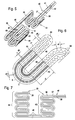
- Fig. 5 is a schematic 3D representation of a coreless bifilar wound in meandering serpentine lines and shaped into a cylindrically curved cartridge coil 35 tubular heating cartridge 36, which is suitable and intended to be placed on a cylindrical machine part to heat this.
- Bifilar means that the tubular heating cartridge 36 two equal length, parallel strands 37, 38 forms, which are integrally connected by a preferably provided with a minimum bending radius arc portion 39.
- This arc portion 39 also forms the beginning of the cartridge snake 35, wherein the end 40 of the two adjacent ends 41 and 42 of the tubular heater 36 is formed.
- This cartridge coil 35 consists of two groups of turns 43 and 44, which are interconnected by a straight cartridge portion 45. It follows that the machine part on which this cartridge snake 35 is placed, in each case more heated in the region of the two winding groups than in the middle section.
- tubular heating cartridge 6 is used in the form of a cartridge coil 12 or 20 or in the form of a cartridge coil 35 or in the form of another distribution system is indifferent per se.
- the achievable by the scheduled sections different winding densities or winding spacings of the heating wire coil 15 advantages are independent of the shape of the tubular heating cartridge.
Landscapes
- Resistance Heating (AREA)
- Yarns And Mechanical Finishing Of Yarns Or Ropes (AREA)
- General Induction Heating (AREA)
Applications Claiming Priority (1)
| Application Number | Priority Date | Filing Date | Title |
|---|---|---|---|
| DE202008015329U DE202008015329U1 (de) | 2008-11-19 | 2008-11-19 | Elektrische Rohrheizpatrone |
Publications (2)
| Publication Number | Publication Date |
|---|---|
| EP2190255A1 true EP2190255A1 (fr) | 2010-05-26 |
| EP2190255B1 EP2190255B1 (fr) | 2011-01-19 |
Family
ID=40299526
Family Applications (1)
| Application Number | Title | Priority Date | Filing Date |
|---|---|---|---|
| EP09013451A Active EP2190255B1 (fr) | 2008-11-19 | 2009-10-24 | Cartouche de chauffage tubulaire électrique |
Country Status (3)
| Country | Link |
|---|---|
| EP (1) | EP2190255B1 (fr) |
| AT (1) | ATE496514T1 (fr) |
| DE (2) | DE202008015329U1 (fr) |
Cited By (3)
| Publication number | Priority date | Publication date | Assignee | Title |
|---|---|---|---|---|
| WO2013153238A1 (fr) * | 2012-04-11 | 2013-10-17 | Jose Rodriguez Rodenas | Résistance de cartouche bipartite à connexion au niveau d'une seule extrémité et d'une seule partie |
| CN109999525A (zh) * | 2019-04-16 | 2019-07-12 | 浙江新锐空分设备有限公司 | 一种用于氪氙精馏塔的蒸发器 |
| GB2573742A (en) * | 2018-04-11 | 2019-11-20 | Exheat Industrial Ltd | A heating element |
Families Citing this family (4)
| Publication number | Priority date | Publication date | Assignee | Title |
|---|---|---|---|---|
| DE202010002136U1 (de) | 2010-02-09 | 2010-05-20 | Türk & Hillinger GmbH | Elektrische Heizvorrichtung |
| DE102018213013A1 (de) * | 2018-08-03 | 2020-02-06 | Thermocoax Isopad Gmbh | Heizvorrichtung zur Beheizung einer Rohrleitung |
| DE202019102573U1 (de) | 2019-05-08 | 2019-07-04 | Türk & Hillinger GmbH | Elektrische Heizpatrone mit Wickelkörper |
| CN115842194A (zh) * | 2022-11-30 | 2023-03-24 | 安徽江淮汽车集团股份有限公司 | 一种可变功率加热丝总成及包含其的圆柱电芯模组 |
Citations (5)
| Publication number | Priority date | Publication date | Assignee | Title |
|---|---|---|---|---|
| DE2907870A1 (de) | 1979-03-01 | 1980-09-04 | Hotset Heizpatronen U Zubehoer | Elektrischer rohrheizkoerper |
| US5575941A (en) * | 1994-08-31 | 1996-11-19 | Johnson; J. Evan | Cartridge heater |
| DE19716010C1 (de) * | 1997-04-17 | 1998-10-29 | Tuerk & Hillinger Gmbh | Elektrischer Mantelrohrheizkörper mit integriertem Temperaturfühler |
| DE20212918U1 (de) * | 2002-08-22 | 2002-10-17 | Türk & Hillinger GmbH, 78532 Tuttlingen | Elektrische Heizeinrichtung für zylindrische Körper |
| DE202005011686U1 (de) * | 2005-07-26 | 2005-10-06 | Türk & Hillinger GmbH | Verdichtete Heizpatrone |
-
2008
- 2008-11-19 DE DE202008015329U patent/DE202008015329U1/de not_active Expired - Lifetime
-
2009
- 2009-10-24 AT AT09013451T patent/ATE496514T1/de active
- 2009-10-24 DE DE502009000324T patent/DE502009000324D1/de active Active
- 2009-10-24 EP EP09013451A patent/EP2190255B1/fr active Active
Patent Citations (5)
| Publication number | Priority date | Publication date | Assignee | Title |
|---|---|---|---|---|
| DE2907870A1 (de) | 1979-03-01 | 1980-09-04 | Hotset Heizpatronen U Zubehoer | Elektrischer rohrheizkoerper |
| US5575941A (en) * | 1994-08-31 | 1996-11-19 | Johnson; J. Evan | Cartridge heater |
| DE19716010C1 (de) * | 1997-04-17 | 1998-10-29 | Tuerk & Hillinger Gmbh | Elektrischer Mantelrohrheizkörper mit integriertem Temperaturfühler |
| DE20212918U1 (de) * | 2002-08-22 | 2002-10-17 | Türk & Hillinger GmbH, 78532 Tuttlingen | Elektrische Heizeinrichtung für zylindrische Körper |
| DE202005011686U1 (de) * | 2005-07-26 | 2005-10-06 | Türk & Hillinger GmbH | Verdichtete Heizpatrone |
Cited By (3)
| Publication number | Priority date | Publication date | Assignee | Title |
|---|---|---|---|---|
| WO2013153238A1 (fr) * | 2012-04-11 | 2013-10-17 | Jose Rodriguez Rodenas | Résistance de cartouche bipartite à connexion au niveau d'une seule extrémité et d'une seule partie |
| GB2573742A (en) * | 2018-04-11 | 2019-11-20 | Exheat Industrial Ltd | A heating element |
| CN109999525A (zh) * | 2019-04-16 | 2019-07-12 | 浙江新锐空分设备有限公司 | 一种用于氪氙精馏塔的蒸发器 |
Also Published As
| Publication number | Publication date |
|---|---|
| EP2190255B1 (fr) | 2011-01-19 |
| ATE496514T1 (de) | 2011-02-15 |
| DE202008015329U1 (de) | 2009-01-29 |
| DE502009000324D1 (de) | 2011-03-03 |
Similar Documents
| Publication | Publication Date | Title |
|---|---|---|
| EP2190255B1 (fr) | Cartouche de chauffage tubulaire électrique | |
| DE2849266C2 (de) | Elektrischer Heizkörper für gasförmige Medien | |
| DE3779828T2 (de) | Schraubenfoermig gewickelter flexibler schlauch. | |
| EP2596274B1 (fr) | Conduite chauffable pour fluides et méthode de sa production | |
| DE19839987C2 (de) | Direktgekühlte Magnetspule, insbesondere Gradientenspule, sowie Verfahren zur Herstellung von Leitern dazu | |
| DE102013212205A1 (de) | Elektrische Heizpatrone und Verfahren zu deren Herstellung | |
| DE202008016439U1 (de) | Heizpatrone | |
| DE202010001576U1 (de) | Elektrische Heizvorrichtung | |
| DE2250778A1 (de) | Elektrisches heizgeraet und verfahren zu seiner herstellung | |
| EP2966933A1 (fr) | Cartouche de chauffage électrique | |
| DE102005019211B3 (de) | Rohrheizkörper mit konischer Heizleiterwendel | |
| DE10333206A1 (de) | Elektrische Heizpatrone für zylindrische Körper | |
| EP1395085B1 (fr) | Appareil de chauffage électrique pour des corps cylindriques | |
| DE102016121571A1 (de) | Wärmeleitkörper für eine Düsenheizung und Düsenheizung | |
| EP0303854B1 (fr) | Radiateur électrique | |
| DE202010003291U1 (de) | Rohrheizpatrone mit mehreren Heizdrahtwendeln | |
| DE10059885C1 (de) | Elektrischer Durchlauferhitzer | |
| DE69405834T2 (de) | Elektrischer Wärmestrahler | |
| DE10224034A1 (de) | Elektrische Heizeinrichtung für zylindrische Körper | |
| EP2348251B1 (fr) | Dispositif de chauffage d'un liquide et procédé de fabrication d'un dispositif de chauffage pour le chauffage d'un liquide | |
| DE19912084A1 (de) | Verfahren zur Herstellung von elektrischen Heizkörpern von Spritzgießwerkzeugen | |
| EP3279541A1 (fr) | Guidage de milieux chauffant et procédé de fabrication d'un tel guidage de milieux chauffant | |
| DE102006001151B3 (de) | Heizerfeld eines Strahlungsheizers mit einer Heizspirale | |
| EP2194753B1 (fr) | Elément de chauffage tubulaire | |
| DE3509985A1 (de) | Elektrisches widerstands-heizelement |
Legal Events
| Date | Code | Title | Description |
|---|---|---|---|
| PUAI | Public reference made under article 153(3) epc to a published international application that has entered the european phase |
Free format text: ORIGINAL CODE: 0009012 |
|
| AK | Designated contracting states |
Kind code of ref document: A1 Designated state(s): AT BE BG CH CY CZ DE DK EE ES FI FR GB GR HR HU IE IS IT LI LT LU LV MC MK MT NL NO PL PT RO SE SI SK SM TR |
|
| AX | Request for extension of the european patent |
Extension state: AL BA RS |
|
| GRAP | Despatch of communication of intention to grant a patent |
Free format text: ORIGINAL CODE: EPIDOSNIGR1 |
|
| 17P | Request for examination filed |
Effective date: 20100726 |
|
| RIC1 | Information provided on ipc code assigned before grant |
Ipc: H05B 3/48 20060101AFI20100812BHEP |
|
| GRAS | Grant fee paid |
Free format text: ORIGINAL CODE: EPIDOSNIGR3 |
|
| GRAA | (expected) grant |
Free format text: ORIGINAL CODE: 0009210 |
|
| AK | Designated contracting states |
Kind code of ref document: B1 Designated state(s): AT BE BG CH CY CZ DE DK EE ES FI FR GB GR HR HU IE IS IT LI LT LU LV MC MK MT NL NO PL PT RO SE SI SK SM TR |
|
| REG | Reference to a national code |
Ref country code: GB Ref legal event code: FG4D Free format text: NOT ENGLISH |
|
| REG | Reference to a national code |
Ref country code: CH Ref legal event code: EP |
|
| REG | Reference to a national code |
Ref country code: IE Ref legal event code: FG4D Free format text: LANGUAGE OF EP DOCUMENT: GERMAN |
|
| REF | Corresponds to: |
Ref document number: 502009000324 Country of ref document: DE Date of ref document: 20110303 Kind code of ref document: P |
|
| REG | Reference to a national code |
Ref country code: DE Ref legal event code: R096 Ref document number: 502009000324 Country of ref document: DE Effective date: 20110303 |
|
| REG | Reference to a national code |
Ref country code: NL Ref legal event code: VDEP Effective date: 20110119 |
|
| LTIE | Lt: invalidation of european patent or patent extension |
Effective date: 20110119 |
|
| PG25 | Lapsed in a contracting state [announced via postgrant information from national office to epo] |
Ref country code: HR Free format text: LAPSE BECAUSE OF FAILURE TO SUBMIT A TRANSLATION OF THE DESCRIPTION OR TO PAY THE FEE WITHIN THE PRESCRIBED TIME-LIMIT Effective date: 20110119 Ref country code: LT Free format text: LAPSE BECAUSE OF FAILURE TO SUBMIT A TRANSLATION OF THE DESCRIPTION OR TO PAY THE FEE WITHIN THE PRESCRIBED TIME-LIMIT Effective date: 20110119 Ref country code: IS Free format text: LAPSE BECAUSE OF FAILURE TO SUBMIT A TRANSLATION OF THE DESCRIPTION OR TO PAY THE FEE WITHIN THE PRESCRIBED TIME-LIMIT Effective date: 20110519 Ref country code: GR Free format text: LAPSE BECAUSE OF FAILURE TO SUBMIT A TRANSLATION OF THE DESCRIPTION OR TO PAY THE FEE WITHIN THE PRESCRIBED TIME-LIMIT Effective date: 20110420 Ref country code: SE Free format text: LAPSE BECAUSE OF FAILURE TO SUBMIT A TRANSLATION OF THE DESCRIPTION OR TO PAY THE FEE WITHIN THE PRESCRIBED TIME-LIMIT Effective date: 20110119 Ref country code: LV Free format text: LAPSE BECAUSE OF FAILURE TO SUBMIT A TRANSLATION OF THE DESCRIPTION OR TO PAY THE FEE WITHIN THE PRESCRIBED TIME-LIMIT Effective date: 20110119 Ref country code: PT Free format text: LAPSE BECAUSE OF FAILURE TO SUBMIT A TRANSLATION OF THE DESCRIPTION OR TO PAY THE FEE WITHIN THE PRESCRIBED TIME-LIMIT Effective date: 20110519 Ref country code: ES Free format text: LAPSE BECAUSE OF FAILURE TO SUBMIT A TRANSLATION OF THE DESCRIPTION OR TO PAY THE FEE WITHIN THE PRESCRIBED TIME-LIMIT Effective date: 20110430 Ref country code: NO Free format text: LAPSE BECAUSE OF FAILURE TO SUBMIT A TRANSLATION OF THE DESCRIPTION OR TO PAY THE FEE WITHIN THE PRESCRIBED TIME-LIMIT Effective date: 20110419 |
|
| REG | Reference to a national code |
Ref country code: IE Ref legal event code: FD4D |
|
| PG25 | Lapsed in a contracting state [announced via postgrant information from national office to epo] |
Ref country code: FI Free format text: LAPSE BECAUSE OF FAILURE TO SUBMIT A TRANSLATION OF THE DESCRIPTION OR TO PAY THE FEE WITHIN THE PRESCRIBED TIME-LIMIT Effective date: 20110119 Ref country code: BG Free format text: LAPSE BECAUSE OF FAILURE TO SUBMIT A TRANSLATION OF THE DESCRIPTION OR TO PAY THE FEE WITHIN THE PRESCRIBED TIME-LIMIT Effective date: 20110419 Ref country code: SI Free format text: LAPSE BECAUSE OF FAILURE TO SUBMIT A TRANSLATION OF THE DESCRIPTION OR TO PAY THE FEE WITHIN THE PRESCRIBED TIME-LIMIT Effective date: 20110119 Ref country code: PL Free format text: LAPSE BECAUSE OF FAILURE TO SUBMIT A TRANSLATION OF THE DESCRIPTION OR TO PAY THE FEE WITHIN THE PRESCRIBED TIME-LIMIT Effective date: 20110119 Ref country code: CY Free format text: LAPSE BECAUSE OF FAILURE TO SUBMIT A TRANSLATION OF THE DESCRIPTION OR TO PAY THE FEE WITHIN THE PRESCRIBED TIME-LIMIT Effective date: 20110119 Ref country code: NL Free format text: LAPSE BECAUSE OF FAILURE TO SUBMIT A TRANSLATION OF THE DESCRIPTION OR TO PAY THE FEE WITHIN THE PRESCRIBED TIME-LIMIT Effective date: 20110119 |
|
| PG25 | Lapsed in a contracting state [announced via postgrant information from national office to epo] |
Ref country code: DK Free format text: LAPSE BECAUSE OF FAILURE TO SUBMIT A TRANSLATION OF THE DESCRIPTION OR TO PAY THE FEE WITHIN THE PRESCRIBED TIME-LIMIT Effective date: 20110119 Ref country code: EE Free format text: LAPSE BECAUSE OF FAILURE TO SUBMIT A TRANSLATION OF THE DESCRIPTION OR TO PAY THE FEE WITHIN THE PRESCRIBED TIME-LIMIT Effective date: 20110119 Ref country code: IE Free format text: LAPSE BECAUSE OF FAILURE TO SUBMIT A TRANSLATION OF THE DESCRIPTION OR TO PAY THE FEE WITHIN THE PRESCRIBED TIME-LIMIT Effective date: 20110119 |
|
| PLBE | No opposition filed within time limit |
Free format text: ORIGINAL CODE: 0009261 |
|
| STAA | Information on the status of an ep patent application or granted ep patent |
Free format text: STATUS: NO OPPOSITION FILED WITHIN TIME LIMIT |
|
| PG25 | Lapsed in a contracting state [announced via postgrant information from national office to epo] |
Ref country code: SK Free format text: LAPSE BECAUSE OF FAILURE TO SUBMIT A TRANSLATION OF THE DESCRIPTION OR TO PAY THE FEE WITHIN THE PRESCRIBED TIME-LIMIT Effective date: 20110119 Ref country code: CZ Free format text: LAPSE BECAUSE OF FAILURE TO SUBMIT A TRANSLATION OF THE DESCRIPTION OR TO PAY THE FEE WITHIN THE PRESCRIBED TIME-LIMIT Effective date: 20110119 Ref country code: RO Free format text: LAPSE BECAUSE OF FAILURE TO SUBMIT A TRANSLATION OF THE DESCRIPTION OR TO PAY THE FEE WITHIN THE PRESCRIBED TIME-LIMIT Effective date: 20110119 |
|
| 26N | No opposition filed |
Effective date: 20111020 |
|
| REG | Reference to a national code |
Ref country code: DE Ref legal event code: R097 Ref document number: 502009000324 Country of ref document: DE Effective date: 20111020 |
|
| BERE | Be: lapsed |
Owner name: TURK + HILLINGER G.M.B.H. Effective date: 20111031 |
|
| PG25 | Lapsed in a contracting state [announced via postgrant information from national office to epo] |
Ref country code: MC Free format text: LAPSE BECAUSE OF NON-PAYMENT OF DUE FEES Effective date: 20111031 |
|
| REG | Reference to a national code |
Ref country code: FR Ref legal event code: ST Effective date: 20120629 |
|
| PG25 | Lapsed in a contracting state [announced via postgrant information from national office to epo] |
Ref country code: BE Free format text: LAPSE BECAUSE OF NON-PAYMENT OF DUE FEES Effective date: 20111031 |
|
| PG25 | Lapsed in a contracting state [announced via postgrant information from national office to epo] |
Ref country code: FR Free format text: LAPSE BECAUSE OF NON-PAYMENT OF DUE FEES Effective date: 20111102 |
|
| PG25 | Lapsed in a contracting state [announced via postgrant information from national office to epo] |
Ref country code: MK Free format text: LAPSE BECAUSE OF FAILURE TO SUBMIT A TRANSLATION OF THE DESCRIPTION OR TO PAY THE FEE WITHIN THE PRESCRIBED TIME-LIMIT Effective date: 20110119 Ref country code: MT Free format text: LAPSE BECAUSE OF FAILURE TO SUBMIT A TRANSLATION OF THE DESCRIPTION OR TO PAY THE FEE WITHIN THE PRESCRIBED TIME-LIMIT Effective date: 20110119 |
|
| PG25 | Lapsed in a contracting state [announced via postgrant information from national office to epo] |
Ref country code: SM Free format text: LAPSE BECAUSE OF FAILURE TO SUBMIT A TRANSLATION OF THE DESCRIPTION OR TO PAY THE FEE WITHIN THE PRESCRIBED TIME-LIMIT Effective date: 20110119 |
|
| PG25 | Lapsed in a contracting state [announced via postgrant information from national office to epo] |
Ref country code: LU Free format text: LAPSE BECAUSE OF NON-PAYMENT OF DUE FEES Effective date: 20111024 |
|
| PG25 | Lapsed in a contracting state [announced via postgrant information from national office to epo] |
Ref country code: TR Free format text: LAPSE BECAUSE OF FAILURE TO SUBMIT A TRANSLATION OF THE DESCRIPTION OR TO PAY THE FEE WITHIN THE PRESCRIBED TIME-LIMIT Effective date: 20110119 |
|
| PG25 | Lapsed in a contracting state [announced via postgrant information from national office to epo] |
Ref country code: HU Free format text: LAPSE BECAUSE OF FAILURE TO SUBMIT A TRANSLATION OF THE DESCRIPTION OR TO PAY THE FEE WITHIN THE PRESCRIBED TIME-LIMIT Effective date: 20110119 |
|
| REG | Reference to a national code |
Ref country code: CH Ref legal event code: PL |
|
| GBPC | Gb: european patent ceased through non-payment of renewal fee |
Effective date: 20131024 |
|
| PG25 | Lapsed in a contracting state [announced via postgrant information from national office to epo] |
Ref country code: CH Free format text: LAPSE BECAUSE OF NON-PAYMENT OF DUE FEES Effective date: 20131031 Ref country code: LI Free format text: LAPSE BECAUSE OF NON-PAYMENT OF DUE FEES Effective date: 20131031 Ref country code: GB Free format text: LAPSE BECAUSE OF NON-PAYMENT OF DUE FEES Effective date: 20131024 |
|
| REG | Reference to a national code |
Ref country code: AT Ref legal event code: MM01 Ref document number: 496514 Country of ref document: AT Kind code of ref document: T Effective date: 20141024 |
|
| PG25 | Lapsed in a contracting state [announced via postgrant information from national office to epo] |
Ref country code: AT Free format text: LAPSE BECAUSE OF NON-PAYMENT OF DUE FEES Effective date: 20141024 |
|
| PGFP | Annual fee paid to national office [announced via postgrant information from national office to epo] |
Ref country code: DE Payment date: 20251125 Year of fee payment: 17 |
|
| PGFP | Annual fee paid to national office [announced via postgrant information from national office to epo] |
Ref country code: IT Payment date: 20251031 Year of fee payment: 17 |