EP2190325B1 - Tasse zur sofortigen gewinnung - Google Patents
Tasse zur sofortigen gewinnung Download PDFInfo
- Publication number
- EP2190325B1 EP2190325B1 EP08738130A EP08738130A EP2190325B1 EP 2190325 B1 EP2190325 B1 EP 2190325B1 EP 08738130 A EP08738130 A EP 08738130A EP 08738130 A EP08738130 A EP 08738130A EP 2190325 B1 EP2190325 B1 EP 2190325B1
- Authority
- EP
- European Patent Office
- Prior art keywords
- cup
- brewing cup
- set forth
- brewing
- coffee
- Prior art date
- Legal status (The legal status is an assumption and is not a legal conclusion. Google has not performed a legal analysis and makes no representation as to the accuracy of the status listed.)
- Active
Links
Images


Classifications
-
- A—HUMAN NECESSITIES
- A47—FURNITURE; DOMESTIC ARTICLES OR APPLIANCES; COFFEE MILLS; SPICE MILLS; SUCTION CLEANERS IN GENERAL
- A47J—KITCHEN EQUIPMENT; COFFEE MILLS; SPICE MILLS; APPARATUS FOR MAKING BEVERAGES
- A47J31/00—Apparatus for making beverages
- A47J31/02—Coffee-making machines with removable extraction cups, to be placed on top of drinking-vessels i.e. coffee-makers with removable brewing vessels, to be placed on top of beverage containers, into which hot water is poured, e.g. cafe filter
Definitions
- the invention relates to disposable hot beverage brewing apparatuses, such as for coffee, tea and herbal products. More particularly, the invention relates to hot beverage disposable containers that contain filter papers that trap solids within the container yet enable fluid to pass.
- the liquid penetrability has been designed through the cup's holes/cutting areas that allow the liquid to penetrate into a lower reservoir cup at a consumer's time limit preferences. The arrangements of how many holes or how big the cutting area will result in how long the extraction should take place (e.g. 2 minutes; 3.5 minutes; or 5 minutes).
- this invention has been designed to provide a proper time and space to provide a stirring movement in a pre packaged 3 in 1 (i.e., coffee, sugar and powder creamer) coffee mix product that comes in a small sachet for one serving.
- the time and space to properly stir is critical in a 3 in 1 coffee mix preparation. Without stirring, the powder creamer that has been homogenously mixed with sugar and coffee, when in contact with hot water will form fat layer (shield effect) that makes the hot water hard to penetrate into the rest of the mixture. The 3 in 1 coffee mix will become clogged and will form a glutinous like compound which makes the extraction process improperly done.
- a brewing apparatus that allows proper stirring is important especially in a pre packaged beverage mixture that contains powder creamer as one of its major ingredients.
- Coffee has been consumed and is known as the oldest beverage in many parts of the world. Thus, there are various devices that have been used to brew coffee. Traditionally, coffee grounds have been brewed in a coffee pot (infusion). Later on, people preferred to brew in electric drip coffee machine due to its conveniences. Moreover, due to the advance of spray-dried technology, instant coffee also has been a choice to many people. These are fair methods to enjoy a cup of coffee; however each one of them has their own drawbacks due to timing, mobility and the fullness of the taste and aroma.
- a product in this category can be categorized as a close-brewing system. In this system, the user is not allowed to perform any kind of modification on the product. This system offers no flexibility to the user either to add or to reduce, for instance, the quantity of the coffee grounds into the pouch/bag.
- US Patent no. 4619830 Napier; Edward D. Scarborough, Ontario, CA ) discloses a brewing apparatus that employed an open-brewing-system that offers a user more flexibility either to add or to reduce, for instance, the quantity of the coffee ground, sugar or powder creamer into the beverage.
- its supporting stick/rod in the middle of its top opening has made it uneasy or troublesome for the user in performing a proper stirring motion during beverage preparation.
- Coffee, tea and herbal products are very sophisticated products. Each required a certain special treatment to get its utmost benefit. Since, all required hot water to extract the sophisticated ingredient contained therein, using a correct brewing apparatus is critical. This invention has been designed to give an accurate result in brewing time.
- This invention has four primary goals. One is to offer to the public an apparatus that correct and accurate, based on written recommendation from Specialty Coffee Association of America, concerning " how long " coffee ground should be in contact with hot water in order to prepare an excellent cup of coffee beverage. Two is to provide an open system brewing apparatus that allows the public to have more flexibility to choose what kind of ingredients to be brewed. Three is to provide a brewing apparatus that has a hot steam releasing vent and also that can be positioned snuggly on top of a regular coffee mug or disposable paper cup. Four is to provide brewing apparatus that is easily stirable in brewing 3 in 1 pre packaged powder beverage that contain powder creamer as one of its major ingredients.
- a cup container comprises a disposable liquid permeable brewing filter that has an open top and partial closed bottom. It is made of coated paper, or polyethylene, or polystyrene, or biodegradable substances including but are not limited to substances such as modified and or unmodified organic fibers and or pulp and or starch or any combination thereof that has number of holes or cutting areas on the bottom of the cup.
- the number of holes or cutting areas is the time control mechanism which produces a critical role in controlling the flow of the liquid from this invention to the bottom of a reservoir cup or mug.
- Each hole represents 28.26 millimeter square. Although the size is perfect to create raindrop size droplets, the hole/cutting area can be varied in size.
- the perforation of the invention comprises an arrangement of about 16.9% (diameter of ( ⁇ )15 mm) to 9.1% ( ⁇ 11 mm) by ratio to the brewers cup bottom base (4183.3 mm 2 ); more preferably from about 7.5% ( ⁇ 10 mm) to 3.7% ( ⁇ 7 mm); more preferably still, from about 2.7% ( ⁇ 6 mm) to 0.68% ( ⁇ 3 mm).
- the shape of the brewer's bottom base opening area can be modified into many kinds of shapes.
- Such modification to the bottom base of the brewer cup is desirable to enhance its aesthetic appearances include, but are not limited to, triangle, rectangle, oval, diamond, flower petal, star, circle, heart, crescent, fan, nonagon, octagon, pentagon, decagon, and hexagon, or any combination thereof.
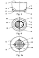
- the cup's bottom has been designed with four concave shapes that are inwardly curving which, in this embodiment, are used to release hot steam buildup during brewing process.
- these corners allowed hot steam that is accumulated on the reservoir cup to be escaped.
- the vent is important to create a resistant-free environment of the liquid flow from top to bottom during brewing process.
- the number of petal shape corner can be maximize or minimize accordingly to the desired output of hot steam released rate.
- the filter paper or other porous material attaches onto the bottom of the cup assembly through hot seal or food grade starch.
- the heat seal is applied about 5 mm width circling along the outer edge of the filter paper onto the cup's bottom.
- the 5 mm heat seal width provides some stretching flexibility to form a better pressure point during droplets drip-down process.
- One alternative embodiment to re-use the cup assembly and throw away the used filter paper in order to preserve natural resources for a better clean environment can be achieved if the filter paper can be easily peeled off by user.
- the hot seal can be done because the commercial filter paper contained Poly Ethylene on one of its side. When applied to heat, PE material melts and become part of the cup assembly.
- the brewing receptacle with multiple holes arrangement has a more stable result than in the other arrangement. And also with the same ratio, multiple holes arrangement has proved to be faster than one single cut arrangement. It is because every cutting area has a pressure point on the middle of that opening. When the filter paper gets wet from the hot water and receives gravity forces, the filter paper will stretch a little and arch in a way to form a pressure point where most of the liquid drips during brewing process. In conclusion to our test, the greater the number of outlets, the faster it will allow the liquid to pass through the filter paper into the reservoir cup/mug.
- the test also showed that one single cut arrangement, for example with 13.51% ratio, has a slower rate (8 second and 53 milli second) result in reaching the 120 ml marking level than 20 multiple cutting arrangement (3 second and 85 milli second) that also has a same ratio.
- the one cutting arrangement has also proved to be less stable and unreliable as a time control mechanism.
- the invention generally provides a disposable brewing apparatus made of inexpensive material such as coated paper board or polystyrene or polyethylene and filter paper. In one alternative, it can also be used to preserve natural resources when just the filter paper is the only part of the entire assembly to be discarded after use.
- a drip-type coffee, or herbal or tea brewer apparatus comprises a disposable cup 10 which can be made from material include but is not limited to a group consisting of polystyrene compounds, plastic, organic and or non organic Bio-degradable polymer, and or modified and or unmodified organic fibers and or pulp and or starch and or coated paperboard and or a combination thereof.
- a partial closed bottom 110 that has an outer diameter about 7.3 cm and sidewalls 105 tapering outwardly towards the top open mouth 103 that has an outer diameter about 8.5 cm.
- the filter cup 10 is constructed of a water permeable or porous material, preferably commercial filter paper 121 which has substantial durability when it is in a wet condition, and which is coated with Polyethylene on one side and comparatively inexpensive so that it can be discarded after a single use.
- the filter paper 121 is attached to the bottom base 110 of the filter cup 10 through heat seal or food grade starch or ultrasonic sealing system or supersonic sealing system.
- the filter cup 10 is designed with plurality number of holes 108 on its bottom base 110 as a time control mechanism which is fundamental to brew different kind of ingredients as each ingredient seems to be needed different time limit to be properly and correctly extracted.
- the area to be hot seal is as wide as around 5 mm along the rim of the circular shape of the filter paper.
- Each hole 108 of the invention represents 28.26 mm2.
- the size of the hole/cutting area 108 can be varied, this size is perfect to create natural water droplets size.
- the accumulation of the water on the pressure point 625 is turned into its maximum size before it starts to drop down as a droplet which falling into a range between 3mm in diameter to 8mm.
- the droplet size when reached to its maximum size does not change accordingly with the perforation change into a bigger size. Therefore to keep it in the maximum range of droplet size will become the most effective way to control drip down process in this type of filter brewer. This is one critical point that set apart this invention from the other inventions that has bigger or too small perforation outlet arrangement.
- Arrangement of the holes or cutting areas 108 is designed to be separated at least 3 mm apart from each hole. This is important to create an individual droplet 630 ( Fig.6 ) without interference from another droplet 630 which is positioned too close to one and another, in order to maintain a standard dropping rate.
- the major benefit of this design is that it creates an independent and uniform size of droplets. As learned from trials, the more standard the dropping rate the more precise its function as a time controlling mechanism. Also the more output to release gravity force the faster it is in accommodating a faster brewing rate.
- a pressure point 625 developed on each and every opening/cutting area when the hot water poured down on the filter cup 10.
- the gravity force pushes down the hot water which in its natural way forms an arch shape that has the lowest point that we refer to pressure point 625 on the filter paper 121.
- There is a plurality of pressure points 625 in Fig.6 while the embodiment of Fig. 7 has only one. Although bigger in cutting size, pressure point 625 in Fig. 7 results in unstable and unpredictable droplets 630.
- the pressure point in Fig.6 which resulted from multiple holes arrangement is more predictable and, as set forth in Table 1, proved to be more stable.
- the heat seal area 109 ( Fig. 3 and Fig. 4 ) is applied at about a 5 mm width circling along the outer edge of the filter paper 121 onto the cup's bottom 110.
- the 5 mm heat seal width provides some stretching flexibility to form a better pressure point 625 ( Fig. 8 ) during the droplets drip-down process.
- the hot seal is possible because the commercial filter paper 121 contains Poly Ethylene on one of its sides. When subjected to heat, the PE material melts and become part of the cup assembly.
- this invention provides a hot steam escaping route.
- the filter cup 10 provides four (4) hot steam escaping vents 201 ( Fig. 1 and Fig. 5a ) on its lower part of the outer sidewall 105.
- the accumulated hot steam has been a problem in brewing devices that are telescopingly assembled.
- the hot steam trapped in the lower liquid receiving cup has been one culprit of the slower extraction process.
- the trapped hot steam has accumulated into a massive force pushing up and thus delayed the drip down process. This indicates that the gravity force is not working in this condition as it is supposed to be.
- the invention has four concave shapes vent 201 that are inwardly curving as deep as about 6 mm; as wide as about 1 cm and tapered upwardly as high as about 2.5 cm.
- the vent 201 main functions are to avoid pressure build-up which can prolong the brewing time during brewing process in the reservoir mug.
- these vents 201 allowed hot steam that is accumulated on the reservoir cup to be escaped ( Fig.1 ).
- the number of petal shape corner can be maximize or minimize accordingly to the desired output of hot steam released (HSR) rate.
- HSR hot steam released
- the filter cup 10 uses the least filter paper 121 amongst any other similar product and is especially most efficient when compared to a tea bag for brewing tea beverage.
- this invention embodiment that has six (6) holes arrangement resulted in about two minutes brewing time which is the same as that recommended in most tea bag brewing methods.
- most tea bag requires 13.140mm2 (with a length of 146mm and width 90mm) of filter paper while this invention needs only 4183 mm2 (3.14 x 36.5mm x 36.5mm) filter paper that is 300% more efficient than most tea bag assemblies in using filter paper.
- an individual hole sealing system is possible to be applied.
- each individual hole 108 with diameter of 5 mm needs only one circular filter paper with diameter of 7 mm to be entirely covered.
- this fabricating method one can save up to 75% of current use (4183.3mm2) and almost 1400% (13140 mm2 divided by 923 mm2) more efficient than most of the tea bag requirements in using filter paper.
- the filter cup 10 is not wasting any unnecessary filter paper 121 like the other brewing methods.
- the filter cup 10 When telescopically engaged into the mouth of the reservoir cup or mug 11 that has a top inner side opening range between 7.2 cm in diameter to 7.5 cm in diameter, the filter cup 10 will fit snuggly on the reservoir cup without any holder.
- the filter cup 10 uses attachable thin (about 3 mm thick x 2.5 cm x 2 cm) rectangular shape polystyrene sheets 610 ( Fig. 2 ) on the bottom part of the outer side of the cup.
- the number of thin polystyrene sheets 610 can be used from one sheet to more than one according to the reservoir's cup top opening width.
- the thin polystyrene sheet 610 can be pre-attached on the filter cup 10 during fabrication or it can be provided with double-sided-tape and attached by user whenever needed.
- the telescopically engagement of the embodiment is the most practical way to hold the cup receptacle firmly with the reservoir cup and thus provide a unique coffee or tea disposable brewer "On the Go" for the portable public.
- the filter cup 10 uses perfectly fit sit-on-ring 233 ( Fig. 9 and Fig. 10 ) which is rounded in shape and has three supporting jagged legs 238 that each has a length about 3.5 cm. Each of the supporting legs 238 is positioned at about one third of the ring's circumference. Each of the supporting legs 238 has a predetermine jagged part on its base 239 which is positioned to lock the filter cup 10 onto the larger top opening of the reservoir cup during the brewing process.
- the material being used for this supporting sit-on-ring 233 can range from sturdy plastic, paper base, wooden, bamboo, or a composite of various metal substances.
- the supporting ring 233 has a width 235 of about 1 cm which is tapered outwardly which and further has a top diameter 236 of about 7.5cm and a bottom diameter 237 of about 7.3cm.
- the filter cup 10 is constructed to include, but is not limited to, material such as plastic and or polymeric, where only the filter paper is to be peeled-off by pulling the semi circle 505 ( Fig. 3 - 4 ) and discarded after each brewing cycle, thus preserving natural resources.
- the durability of this invention can also be prolonged to a further level of effectiveness and efficiency when the cup is made from, but is not limited to, material such as Poly Ethylene and or Poly Styrene or the combination thereof having a well know durability. With using these materials, the economic value of the cup itself will become very insignificant due to its capability to be used over and over again. The only part that is discarded throughout the brewing cycle is the filter paper 121 that is easy to be recycled.
- This invention significantly promotes a clean environment through recycling only the part that is important to the brewing process and allowing the supporting material (the cup assembly 10) to be used again and again.
- the hot seal of filter paper 121 onto the paper, polystyrene, or polyethylene cup is easily done.
- a simple tool like solder that is inexpensive and considered as an average household tool can be modified into a food grade (stainless steel) heating tip and used to seal the filter paper 121 onto the bottom 110 of the filter cup 10.
- Another alternative is to use a same shape and size of HVS paper or protection material commonly used in ironing to prevent the conventional solder from directly touching the filter paper 121.
- the filter paper is seal-able because it contains Poly Ethylene on one of its sides.
- the filter paper has been cut in circular shape with two predetermined semi circles 505 on each of its poles ( Fig. 3-4 ) that is used to ease the peeling off process of the filter paper 121 after washing. It is easier to peel off the filter paper 121 when it is wet. After drying, a new filter paper is ready to be sealed onto the cup which creates another reusable new brewing device.
- the method of re-coating includes but is not limited to brush, spray, and or immersion.
- a further alternative to avoid a recoating process after puncturing the perforation 108 on the paper cup's base 110 is to change the paper cup's base 110 material to material including, but not limited to, polystyrene, biodegradable substances such as modified and or unmodified organic fibers and or pulp and or starch and or polyethylene.
- the cup's base 110 made of polystyrene and or biodegradable substances and or polyethylene is fed into the paper cup forming machine to be integrated into a new combination of cup that has a paper coated wall 105 and polyethylene and or biodegradable substances and or polystyrene bottom base 110. With this combination, the need to coat the perforation 108 is eliminated because the material being used is food grade.
- the new combination cup reduces the need to punch the perforation 108 during fabrication. This is because the perforation 108, made with material such as polyethylene and or polystyrene, is formed in a mold that has a predetermined number of perforations during forming the cup's base 110.
- the perforation is formed into a half cut 107 with a small part 107a. (about one fifth of its total base area) bulging out from the filter cup's base 110 to allow easy pull-off or peel-off when necessary by one in preparing a specific need of brewing.
- the half cut 107 is structured with many small-cut-and-gaps along the outer edge of the perforation but does not puncture it loose from the filter cup's base 110. Although some small leaking may appear from the un-peeled perforation, this method allows a user to custom peel-off any number of perforations he/she desires in order to perform his/her specific brewing need.
- the filter cup 10 may be formed into an accordion like structure.
- the accordion shape or structure (best seen on Fig. 5c and Fig.5d ) of the cup can be formed during fabrication by using a specific molding treatment and or heat treatment and or pressure forming or the combination thereof directly or indirectly influenced in all or in part of the filter cup's wall 105.
- the accordion shape or structure of the filter cup 10 can allow the cup to shorten or flatten ( Fig. 5d ) and thus can be fitted into a single serving pack. When the pack is opened, one can easily pull the flattened cup into a regular height ( Fig. 5c ) filter cup without altering the cup's main function as a filter apparatus.
- the filter cup 10 has been assembled in the manner described and illustrated, and is supported on top of the mug.
- a small pre-mix sachet that contained about 25 grams of ground coffee 612 plus sugar plus powder creamer is opened and poured onto the filter cup 10.
- the hot water reaches a suitable degree, the hot water is then poured into the filter cup 10 and fills the cup almost to the top opening 103.
- the drip down process starts immediately but still provides enough time to do the stirring movement on the mixture.
- a back and forth stirring movement of about 30 seconds to one minute is required when the hot water is fully filled in the filter cup 10.
- a proper stirring movement is crucial to break the shield effect of the fat layer created when in contact with the hot water.
- the user When the stirring process is done, the user only needs to wait until the mixed beverage has dripped down entirely onto the coffee mug. Furthermore, the filter paper 121 has trapped all the unextractable ingredients on the assembly of the filter cup 10. The beverage brewed in the filter cup 10 seeps through the filter paper, drips down the other side thereof into the mug. Once the water level is low and the drip down process is considered slow on the filter cup 10, the filter cup 10 can be easily pulled out and discarded. Instantly, the coffee beverage can then be consumed.
- the filter cup 10 can accommodate a reasonable volume (160 ml) of hot water required for brewing one serving of coffee or tea beverage (which usually only requires about 150 ml) on one single pouring. Moreover, the filter cup 10 is designed to provide easiness on the pouring effort even on the larger cup with at most two simple pourings. There is no need to pour a small volume and then wait and then repeatedly do the same thing until the beverage is ready to consume, like some existing brewing methods that use filter elements.
- the arrangement of the holes/cutting areas 108 on the bottom base 110 of the filter cup 10 can be arranged by the plurality of outlets to result in a drip time in a range of about 1 minute to 13 minutes or longer depending on the specific need of brewing ingredient and time.
- the size of the hole/cutting area can be also modified into larger or smaller sizes to satisfy with a specific brewing requirement.
- the shape of the opening or cutting area can be differentiated into many forms (such as company logo; characters; company's Icon or the like) as to make it fancier and enhanced its aesthetic appearances.
- the filter cup 10 may be approximately 4.7 cm high and have an open upper surface approximately 8.5 cm in diameter and a lower partially open bottom 7.3 cm in diameter.
Landscapes
- Engineering & Computer Science (AREA)
- Food Science & Technology (AREA)
- Apparatus For Making Beverages (AREA)
- Fittings On The Vehicle Exterior For Carrying Loads, And Devices For Holding Or Mounting Articles (AREA)
- Instrument Panels (AREA)
- Glass Compositions (AREA)
- Inorganic Insulating Materials (AREA)
Claims (18)
- Getränkebrauvorrichtung, die daran angepasst ist, frische, ausziehbare Ingredienzien in einen Flüssigkeit aufnehmenden Behälter (11) zu extrahieren und die Folgendes aufweist:- eine Wegwerfbrautasse (10) mit einer oberen Öffnung (103) und einem durchlässigen Boden (110),- ein Blatt eines Filterelements (121) auf der Fläche des Bodens (110),- Perforationen (108) im Boden (110), die daran angepasst sind, Wassertropfen von natürlicher Größe zu erzeugen,- mindestens einen konkaven Entlüftungskanal (201), der an einem unteren Teil der Brautasse vorhanden ist,dadurch gekennzeichnet, dass- das Filterelement (121) an einem Randstreifen (109) des Bodens (110) der Brautasse (10) mittels einer ungiftigen, schmelzbaren, im Filterelement (121) enthaltenen Substanz mindestens 1mm breit abgedichtet ist,- mindestens ein eine Lüftung vorsehendes Polystyrolblatt (610) vorgesehen ist, das am unteren Teil der Brautasse (10) positionierbar ist, und- ein Einsatzring vorgesehen ist, der einen konisch zulaufenden, kreisförmigen Ring (233) und drei gezackte Stützbeine (238) zur Stützung der Brautasse (10) auf dem die Flüssigkeit aufnehmenden Behälter (11) aufweist.
- Getränkebrauvorrichtung nach Anspruch 1,
dadurch gekennzeichnet,
dass die Brautasse normalerweise eine gewisse Standardmenge an Flüssigkeit und eine gewisse Standardmenge an ausziehbaren Ingredienzien aufnimmt, um ein Standardgetränkevolumen zu erzeugen. - Getränkebrauvorrichtung nach Anspruch 1,
dadurch gekennzeichnet,
dass die Brautasse (10) aus einem Material hergestellt ist, das aus einer Gruppe ausgewählt ist, die aus Polystyrolverbindungen, Kunststoff, organischem, biologisch abbaubarem Polymer, nicht organischem Polymer, modifizierten und nicht modifizierten, organischen Fasern und/oder Pulpe und/oder Stärke und beschichteter Pappe besteht. - Getränkebrauvorrichtung nach Anspruch 1,
dadurch gekennzeichnet,
dass die Brautasse (10) aus einer Materialkombination hergestellt ist, die aus einer Gruppe ausgewählt ist, die aus Polystyrolverbindungen, Kunststoff, organischem, biologisch abbaubarem Polymer, nicht organischem Polymer, modifizierten und nicht modifizierten, organischen Fasern und/oder Pulpe und/oder Stärke und beschichteter Pappe besteht. - Getränkebrauvorrichtung nach Anspruch 1,
dadurch gekennzeichnet,
dass das genannte Abdichtverfahren des Blatts des Filterelements (121) darin besteht, dass eine Streckflexibilität vorgesehen ist, die zur Bildung eines ausreichenden Bogens auf den Druckpunkten (625) erforderlich ist. - Getränkebrauvorrichtung nach Anspruch 1,
dadurch gekennzeichnet,
dass die Perforation (108) derart beschaffen ist, dass sie an etwa die maximale Größe der Wassertropfen (630) angepasst ist, wenn diese in einer ähnlichen Brautasse mit einem ähnlichen Wasservolumen und einer ähnlichen Schwerkraft angewendet werden. - Getränkebrauvorrichtung nach Anspruch 1,
dadurch gekennzeichnet,
dass die genannte, untere Wand der Brautasse (10) im Querschnitt kreisförmig ist. - Getränkebrauvorrichtung nach Anspruch 1,
dadurch gekennzeichnet,
dass die Brautasse (10) derart angepasst ist, dass sie eine Flüssigkeitsmenge aufnimmt und für die Flüssigkeit mittels der Perforation (108) durchlässig ist. - Getränkebrauvorrichtung nach Anspruch 1,
dadurch gekennzeichnet,
dass die Perforationen (108) mindestens 1 mm entfernt voneinander angeordnet sind. - Getränkebrauvorrichtung nach Anspruch 1,
dadurch gekennzeichnet,
dass jede der Perforationen (108) eine Fläche von etwa 28,26mm2 aufweist. - Getränkebrauvorrichtung nach Anspruch 1,
dadurch gekennzeichnet,
dass das Filterelement (121) über einen Bereich wärmeabgedichtet ist, der sich etwa 5mm kreisförmig längs der Außenkante bis zum Boden (110) der Brautasse (10) erstreckt. - Getränkebrauvorrichtung nach Anspruch 1,
dadurch gekennzeichnet,
dass der Lüftungskanal (201) am unteren Teil der Seitenaußenwand der Brautasse angeordnet ist. - Getränkebrauvorrichtung nach Anspruch 12,
dadurch gekennzeichnet,
dass die Lüftungskanäle (201) gleichmäßig auf vier Querschnittsseiten der Brautasse verteilt sind. - Getränkebrauvorrichtung nach Anspruch 12,
dadurch gekennzeichnet,
dass der Lüftungskanal (201) eine nach innen konkav ausgebildete Ecke mit einer Tiefe von 6mm und mit einer Breite von 1 cm aufweist, wobei diese Ecke sich über eine Höhe von 2,5cm der Außenwand (105) der Brautasse verjüngt. - Getränkebrauvorrichtung nach Anspruch 1,
dadurch gekennzeichnet,
dass das den Lüftungskanal vorsehende Polystyrolblatt (610) am Bodenteil der Außenseite der Brautasse (10) befestigbar ist. - Getränkebrauvorrichtung nach Anspruch 15,
dadurch gekennzeichnet,
dass das den Lüftungskanal vorsehende Polystyrolblatt (610) rechteckförmig und mit einer Stärke von etwa 3mm, einer Länge von etwa 2,5cm und einer Breite von etwa 2cm ausgebildet ist. - Getränkebrauvorrichtung nach Anspruch 1,
dadurch gekennzeichnet,
dass der stützende Einsatzring (233) ringförmig ausgebildet und teleskopartig an den unteren Teil der Brautasse (10) zur Stützung der Brautasse (10) über dem die Flüssigkeit aufnehmenden Behälter (11) angepasst ist, wobei die oberen Teile des stützenden Einsatzrings (233) sich nach unten verjüngen und mit einer Breite von 1cm sowie einer Auswärtsverjüngung versehen sind, die einen oberen Durchmesser von 7,5cm und einen unteren Durchmesser von 7,3cm aufweist. - Getränkebrauvorrichtung nach Anspruch 17,
dadurch gekennzeichnet,
dass die Stützbeine (238) auf den oberen Teil des Behälters (11) positionierbar sind und einen gezackten Sperrteil (239) aufweisen, der sich von den Stützbeinen derart erstreckt, dass er in die obere Öffnung des Behälters (11) eingreift und dabei die Brautasse an Ort und Stelle in einer festen Orientierung in dem die Flüssigkeit aufnehmenden Behälter (11) zurückhält.
Applications Claiming Priority (3)
| Application Number | Priority Date | Filing Date | Title |
|---|---|---|---|
| US92639307P | 2007-04-25 | 2007-04-25 | |
| ID20070546 | 2007-10-01 | ||
| PCT/ID2008/000002 WO2008132705A1 (en) | 2007-04-25 | 2008-02-25 | Instant extraction cup |
Publications (2)
| Publication Number | Publication Date |
|---|---|
| EP2190325A1 EP2190325A1 (de) | 2010-06-02 |
| EP2190325B1 true EP2190325B1 (de) | 2011-04-13 |
Family
ID=39885460
Family Applications (1)
| Application Number | Title | Priority Date | Filing Date |
|---|---|---|---|
| EP08738130A Active EP2190325B1 (de) | 2007-04-25 | 2008-02-25 | Tasse zur sofortigen gewinnung |
Country Status (6)
| Country | Link |
|---|---|
| US (2) | US7856922B2 (de) |
| EP (1) | EP2190325B1 (de) |
| CN (1) | CN101686769A (de) |
| AT (1) | ATE505118T1 (de) |
| DE (1) | DE602008006214D1 (de) |
| WO (1) | WO2008132705A1 (de) |
Families Citing this family (27)
| Publication number | Priority date | Publication date | Assignee | Title |
|---|---|---|---|---|
| TWI401052B (zh) * | 2007-04-25 | 2013-07-11 | Tjen Eddy | 飲料泡製裝置 |
| US8043645B2 (en) | 2008-07-09 | 2011-10-25 | Starbucks Corporation | Method of making beverages with enhanced flavors and aromas |
| US20110271844A1 (en) * | 2009-01-02 | 2011-11-10 | Alain Mariller | Capsule for preparing a beverage, and device |
| MX2011010171A (es) * | 2009-03-27 | 2011-10-10 | Pur Water Purification Prod | Dispositivos formadores de gotitas para el tratamiento de fluidos y metodos para formar gotitas filtradas en un dispositivo de tratamiento de fluidos. |
| IT1393999B1 (it) * | 2009-04-01 | 2012-05-17 | Rancilio Macchine Caffe | Macchina per la preparazione di infusi, in particolare caffe' espresso, gruppo erogatore e metodo di realizzazione della stessa |
| TWM369718U (en) * | 2009-07-17 | 2009-12-01 | Pegatron Corp | Disposable tea set and tea pot thereof |
| US20110192750A1 (en) * | 2009-10-14 | 2011-08-11 | Sector Labs | Room For System |
| DE102010031842A1 (de) * | 2010-07-22 | 2012-01-26 | Rt-Filtertechnik Gmbh | Filterelement zur Filtration von Fluiden |
| US20120073448A1 (en) * | 2010-09-23 | 2012-03-29 | Husted Royce Hill | Coffee maker with computerized steeping control |
| US20130019754A1 (en) * | 2011-07-22 | 2013-01-24 | Pao-Wu Tien | Brewing device with leak-proof structure |
| US10450130B2 (en) * | 2012-09-12 | 2019-10-22 | Kraft Foods R & D, Inc. | Cartridges, systems and methods for preparation of beverages |
| US8906436B2 (en) | 2013-03-15 | 2014-12-09 | Ptc-Innovations, Llc | Single serve beverage additive cartridge |
| US10278534B2 (en) * | 2013-12-01 | 2019-05-07 | Fellow Industries Inc. | Beverage steeping and dispensing system |
| TWI568394B (zh) | 2015-07-20 | 2017-02-01 | 吉諾工業有限公司 | 飲料沖泡裝置 |
| CN106361148B (zh) * | 2015-07-23 | 2019-10-29 | 吉诺工业有限公司 | 饮料冲泡装置 |
| KR102071046B1 (ko) * | 2018-02-05 | 2020-01-28 | 주식회사 이노디자인 | 드립핑 용기 및 휴대용 커피 음용 용기 |
| CN111801035B (zh) | 2018-03-14 | 2023-04-21 | 雀巢产品有限公司 | 具有部分打开的分配面的饮料机器 |
| US10595663B2 (en) * | 2018-05-10 | 2020-03-24 | Reginald Osagie Akpata | Edo cup 2.0 |
| CN111511256B (zh) * | 2018-10-26 | 2022-05-10 | 李玉明 | 具有压力调节功能的冲泡工具套组 |
| CN110101308A (zh) * | 2019-05-27 | 2019-08-09 | 冯磊 | 一种限制流量的茶叶滤杯、茶具及该滤杯的参数确定方法 |
| CN110150979B (zh) * | 2019-05-31 | 2021-09-14 | 艾迪·田 | 一种饮料冲泡装置 |
| USD953801S1 (en) | 2019-08-19 | 2022-06-07 | Espro, Inc. | Pour over brewing device |
| US11583130B2 (en) * | 2019-10-18 | 2023-02-21 | Timothy Arthur Bindon | Beverage brewing assembly |
| USD929804S1 (en) | 2019-12-02 | 2021-09-07 | Espro, Inc. | Filter element |
| DE102020104079B3 (de) * | 2020-02-17 | 2021-01-21 | Wolfgang Muckenhuber | Filtergefäß, Vorrichtung und Verfahren zur Herstellung eines Filtrats |
| BE1028065B1 (nl) * | 2020-02-18 | 2021-09-15 | Koffie F Rombouts | Filter voor de bereiding van koffie of infuus |
| CN112129072B (zh) * | 2020-09-21 | 2021-11-23 | 大连交通大学 | 一种咖啡渣再利用的装置及方法 |
Family Cites Families (33)
| Publication number | Priority date | Publication date | Assignee | Title |
|---|---|---|---|---|
| US7490542B2 (en) * | 1920-02-11 | 2009-02-17 | I.T.A.Ca S.R.L. | Cartridge for coffee and soluble products and relative method of producing a beverage and apparatus for extracting a beverage |
| US2329608A (en) * | 1941-02-10 | 1943-09-14 | Graham | Tea making apparatus |
| FR914538A (fr) * | 1945-09-17 | 1946-10-10 | Cafetière | |
| US2607338A (en) * | 1950-04-04 | 1952-08-19 | Fred L Parenti | Juice catcher for cooking utensils |
| US2885290A (en) * | 1955-12-19 | 1959-05-05 | Krasker Abraham | Instantaneous coffee beverage |
| US3252403A (en) * | 1962-10-19 | 1966-05-24 | Polizzi Anthony Charles | Coffee filter |
| US3270658A (en) * | 1963-10-09 | 1966-09-06 | Tavera Antonio | Coffee maker |
| US3985069A (en) * | 1973-12-03 | 1976-10-12 | Cavalluzzi Frank J | Coffee beverage drip brewer |
| US4069751A (en) * | 1977-01-10 | 1978-01-24 | Sunbeam Corporation | Coffee brewing apparatus |
| US4174659A (en) * | 1977-11-14 | 1979-11-20 | Econo-Brew, Inc. | Coffee brewer |
| US4158329A (en) * | 1978-04-24 | 1979-06-19 | Mcknight Robert J | Drip coffee brewer |
| US5036755A (en) * | 1980-05-27 | 1991-08-06 | Abdenour Joseph D | Brewing improvement |
| US4446158A (en) * | 1982-06-08 | 1984-05-01 | English Philip H | Apparatus for making individual beverage quantities |
| US4520716A (en) * | 1984-03-19 | 1985-06-04 | Hayes Susan M | Drip-type coffee making apparatus |
| US4577080A (en) * | 1985-03-19 | 1986-03-18 | Gee Associates | Coffee maker adapted for use in a microwave oven |
| US4739697A (en) * | 1987-05-04 | 1988-04-26 | Bloomfield Industries, Inc. | Brew chamber with filter spacer |
| US4867880A (en) * | 1988-10-14 | 1989-09-19 | D.J. Incorporated | Brewing device |
| US4908222A (en) * | 1989-02-16 | 1990-03-13 | Dong Yu | Microwave brewing apparatus and method |
| US5064980A (en) * | 1990-06-11 | 1991-11-12 | Gee Associates | Coffee maker |
| US5010221A (en) * | 1990-06-11 | 1991-04-23 | Gee Associates | Microwaveable coffee makers |
| US5243164A (en) * | 1990-12-14 | 1993-09-07 | Gee Associates | Beverage maker |
| CA2184298C (fr) * | 1996-08-27 | 1998-08-18 | Yvan St-Gelais | Cafetiere a filtre permanent |
| US5632194A (en) * | 1996-10-30 | 1997-05-27 | Lin; Yu-Mei | Infusion maker |
| US6327084B1 (en) * | 1997-06-30 | 2001-12-04 | Central Glass Company, Limited | Display system where polarized light impinges on platelike laminate at brewster's angle or emerges therefrom at angle equal thereto |
| CN1108964C (zh) * | 1998-09-30 | 2003-05-21 | 日清食品株式会社 | 食品容器用盖件 |
| JP2001275842A (ja) * | 2000-03-30 | 2001-10-09 | Tatsuo Ikoma | 機能性フィルタ、その製造方法およびそれを用いた抽出装置 |
| US6443573B2 (en) * | 2000-08-10 | 2002-09-03 | Yazaki Corporation | On-vehicle display unit |
| AU735073B3 (en) * | 2000-10-11 | 2001-06-28 | Nick O'loughlin | Cup plunger |
| AU2002230209A1 (en) * | 2002-02-08 | 2003-09-02 | Farnge Co., Ltd. | Functional filter, method for manufacturing the filter, and extracting device using the filter |
| US6889599B2 (en) * | 2002-04-16 | 2005-05-10 | Koslow Technologies Corporation | Brewing apparatus and method |
| US7258450B2 (en) * | 2003-12-04 | 2007-08-21 | Sharp Kabushiki Kaisha | Projector optical system configuration, optical module, and projector, and also electronic equipment, vehicle, projection system, and showcase utilizing such projector |
| US7131728B2 (en) * | 2003-12-31 | 2006-11-07 | Symbol Technologies, Inc. | Method and apparatus for displaying information in automotive application using a laser projection display |
| US7175321B1 (en) * | 2004-03-24 | 2007-02-13 | Lopez Gustavo M | Projector systems |
-
2007
- 2007-11-30 US US11/947,901 patent/US7856922B2/en not_active Expired - Fee Related
-
2008
- 2008-02-25 AT AT08738130T patent/ATE505118T1/de not_active IP Right Cessation
- 2008-02-25 CN CN200880021249A patent/CN101686769A/zh active Pending
- 2008-02-25 EP EP08738130A patent/EP2190325B1/de active Active
- 2008-02-25 WO PCT/ID2008/000002 patent/WO2008132705A1/en not_active Ceased
- 2008-02-25 DE DE602008006214T patent/DE602008006214D1/de active Active
- 2008-04-04 US US12/098,137 patent/US20090027621A1/en not_active Abandoned
Also Published As
| Publication number | Publication date |
|---|---|
| ATE505118T1 (de) | 2011-04-15 |
| DE602008006214D1 (de) | 2011-05-26 |
| CN101686769A (zh) | 2010-03-31 |
| WO2008132705A1 (en) | 2008-11-06 |
| EP2190325A1 (de) | 2010-06-02 |
| US20080264268A1 (en) | 2008-10-30 |
| US20090027621A1 (en) | 2009-01-29 |
| US7856922B2 (en) | 2010-12-28 |
Similar Documents
| Publication | Publication Date | Title |
|---|---|---|
| EP2190325B1 (de) | Tasse zur sofortigen gewinnung | |
| CN100480150C (zh) | 用于制备泡制饮料的盒 | |
| CN102958408B (zh) | 用于泡制饮料的方法和包含可浸泡材料的储盒 | |
| CN102123922B (zh) | 特别是用于一次性杯子的盖 | |
| US6007853A (en) | Disposable beverage infuser | |
| CN1099267C (zh) | 用来制作饮料的浸泡器单元 | |
| US20040020368A1 (en) | Device and method for brewing coffee & espresso beverages | |
| US20050160918A1 (en) | Apparatus for making brewed coffee and the like | |
| US20090223377A1 (en) | Permanent filtering pod for brewing beverages | |
| WO2005076698A2 (en) | Brewing filter apparatus | |
| EP1513741B1 (de) | Filter für aufbrühvorrichtung | |
| US3095801A (en) | Beverage percolating apparatus with unit dry beverage container | |
| US3357340A (en) | Coffee brewing apparatus | |
| CN110150979B (zh) | 一种饮料冲泡装置 | |
| CN210300666U (zh) | 一种饮料冲泡装置 | |
| WO2006052257A1 (en) | Apparatus for making brewed coffee and the like | |
| JP3673944B2 (ja) | お茶の淹れ方 | |
| TWI401052B (zh) | 飲料泡製裝置 | |
| KR102733953B1 (ko) | 휴대가능하면서 커피내리는 기구 | |
| JP5994046B2 (ja) | ティーバッグ用蓋付き茶器 | |
| KR200418154Y1 (ko) | 일체형 거름망을 구비한 다구 | |
| US20260021955A1 (en) | Disposable single serve liquor coffee beverage pod with one compartment for containing coffee and a separate compartment for containing liquor | |
| GB2384689A (en) | Infusion device for beverage making | |
| JP2008194254A (ja) | コーヒードリッパー | |
| JP2025009061A (ja) | コーヒー豆保存バッグ、コーヒー抽出方法および飲食店等においてコーヒーを提供する方法 |
Legal Events
| Date | Code | Title | Description |
|---|---|---|---|
| PUAI | Public reference made under article 153(3) epc to a published international application that has entered the european phase |
Free format text: ORIGINAL CODE: 0009012 |
|
| 17P | Request for examination filed |
Effective date: 20100324 |
|
| AK | Designated contracting states |
Kind code of ref document: A1 Designated state(s): AT BE BG CH CY CZ DE DK EE ES FI FR GB GR HR HU IE IS IT LI LT LU LV MC MT NL NO PL PT RO SE SI SK TR |
|
| AX | Request for extension of the european patent |
Extension state: AL BA MK RS |
|
| DAX | Request for extension of the european patent (deleted) | ||
| GRAP | Despatch of communication of intention to grant a patent |
Free format text: ORIGINAL CODE: EPIDOSNIGR1 |
|
| GRAS | Grant fee paid |
Free format text: ORIGINAL CODE: EPIDOSNIGR3 |
|
| GRAA | (expected) grant |
Free format text: ORIGINAL CODE: 0009210 |
|
| AK | Designated contracting states |
Kind code of ref document: B1 Designated state(s): AT BE BG CH CY CZ DE DK EE ES FI FR GB GR HR HU IE IS IT LI LT LU LV MC MT NL NO PL PT RO SE SI SK TR |
|
| REG | Reference to a national code |
Ref country code: GB Ref legal event code: FG4D |
|
| REG | Reference to a national code |
Ref country code: CH Ref legal event code: EP |
|
| REG | Reference to a national code |
Ref country code: IE Ref legal event code: FG4D |
|
| REF | Corresponds to: |
Ref document number: 602008006214 Country of ref document: DE Date of ref document: 20110526 Kind code of ref document: P |
|
| REG | Reference to a national code |
Ref country code: DE Ref legal event code: R096 Ref document number: 602008006214 Country of ref document: DE Effective date: 20110526 |
|
| REG | Reference to a national code |
Ref country code: NL Ref legal event code: VDEP Effective date: 20110413 |
|
| LTIE | Lt: invalidation of european patent or patent extension |
Effective date: 20110413 |
|
| PG25 | Lapsed in a contracting state [announced via postgrant information from national office to epo] |
Ref country code: SE Free format text: LAPSE BECAUSE OF FAILURE TO SUBMIT A TRANSLATION OF THE DESCRIPTION OR TO PAY THE FEE WITHIN THE PRESCRIBED TIME-LIMIT Effective date: 20110413 Ref country code: HR Free format text: LAPSE BECAUSE OF FAILURE TO SUBMIT A TRANSLATION OF THE DESCRIPTION OR TO PAY THE FEE WITHIN THE PRESCRIBED TIME-LIMIT Effective date: 20110413 Ref country code: NO Free format text: LAPSE BECAUSE OF FAILURE TO SUBMIT A TRANSLATION OF THE DESCRIPTION OR TO PAY THE FEE WITHIN THE PRESCRIBED TIME-LIMIT Effective date: 20110713 Ref country code: PT Free format text: LAPSE BECAUSE OF FAILURE TO SUBMIT A TRANSLATION OF THE DESCRIPTION OR TO PAY THE FEE WITHIN THE PRESCRIBED TIME-LIMIT Effective date: 20110816 Ref country code: LT Free format text: LAPSE BECAUSE OF FAILURE TO SUBMIT A TRANSLATION OF THE DESCRIPTION OR TO PAY THE FEE WITHIN THE PRESCRIBED TIME-LIMIT Effective date: 20110413 |
|
| PG25 | Lapsed in a contracting state [announced via postgrant information from national office to epo] |
Ref country code: ES Free format text: LAPSE BECAUSE OF FAILURE TO SUBMIT A TRANSLATION OF THE DESCRIPTION OR TO PAY THE FEE WITHIN THE PRESCRIBED TIME-LIMIT Effective date: 20110724 Ref country code: IS Free format text: LAPSE BECAUSE OF FAILURE TO SUBMIT A TRANSLATION OF THE DESCRIPTION OR TO PAY THE FEE WITHIN THE PRESCRIBED TIME-LIMIT Effective date: 20110813 Ref country code: CY Free format text: LAPSE BECAUSE OF FAILURE TO SUBMIT A TRANSLATION OF THE DESCRIPTION OR TO PAY THE FEE WITHIN THE PRESCRIBED TIME-LIMIT Effective date: 20110413 Ref country code: FI Free format text: LAPSE BECAUSE OF FAILURE TO SUBMIT A TRANSLATION OF THE DESCRIPTION OR TO PAY THE FEE WITHIN THE PRESCRIBED TIME-LIMIT Effective date: 20110413 Ref country code: BE Free format text: LAPSE BECAUSE OF FAILURE TO SUBMIT A TRANSLATION OF THE DESCRIPTION OR TO PAY THE FEE WITHIN THE PRESCRIBED TIME-LIMIT Effective date: 20110413 Ref country code: LV Free format text: LAPSE BECAUSE OF FAILURE TO SUBMIT A TRANSLATION OF THE DESCRIPTION OR TO PAY THE FEE WITHIN THE PRESCRIBED TIME-LIMIT Effective date: 20110413 Ref country code: AT Free format text: LAPSE BECAUSE OF FAILURE TO SUBMIT A TRANSLATION OF THE DESCRIPTION OR TO PAY THE FEE WITHIN THE PRESCRIBED TIME-LIMIT Effective date: 20110413 Ref country code: GR Free format text: LAPSE BECAUSE OF FAILURE TO SUBMIT A TRANSLATION OF THE DESCRIPTION OR TO PAY THE FEE WITHIN THE PRESCRIBED TIME-LIMIT Effective date: 20110714 Ref country code: SI Free format text: LAPSE BECAUSE OF FAILURE TO SUBMIT A TRANSLATION OF THE DESCRIPTION OR TO PAY THE FEE WITHIN THE PRESCRIBED TIME-LIMIT Effective date: 20110413 |
|
| PG25 | Lapsed in a contracting state [announced via postgrant information from national office to epo] |
Ref country code: NL Free format text: LAPSE BECAUSE OF FAILURE TO SUBMIT A TRANSLATION OF THE DESCRIPTION OR TO PAY THE FEE WITHIN THE PRESCRIBED TIME-LIMIT Effective date: 20110413 |
|
| PG25 | Lapsed in a contracting state [announced via postgrant information from national office to epo] |
Ref country code: EE Free format text: LAPSE BECAUSE OF FAILURE TO SUBMIT A TRANSLATION OF THE DESCRIPTION OR TO PAY THE FEE WITHIN THE PRESCRIBED TIME-LIMIT Effective date: 20110413 Ref country code: CZ Free format text: LAPSE BECAUSE OF FAILURE TO SUBMIT A TRANSLATION OF THE DESCRIPTION OR TO PAY THE FEE WITHIN THE PRESCRIBED TIME-LIMIT Effective date: 20110413 |
|
| PLBE | No opposition filed within time limit |
Free format text: ORIGINAL CODE: 0009261 |
|
| STAA | Information on the status of an ep patent application or granted ep patent |
Free format text: STATUS: NO OPPOSITION FILED WITHIN TIME LIMIT |
|
| PG25 | Lapsed in a contracting state [announced via postgrant information from national office to epo] |
Ref country code: RO Free format text: LAPSE BECAUSE OF FAILURE TO SUBMIT A TRANSLATION OF THE DESCRIPTION OR TO PAY THE FEE WITHIN THE PRESCRIBED TIME-LIMIT Effective date: 20110413 Ref country code: SK Free format text: LAPSE BECAUSE OF FAILURE TO SUBMIT A TRANSLATION OF THE DESCRIPTION OR TO PAY THE FEE WITHIN THE PRESCRIBED TIME-LIMIT Effective date: 20110413 Ref country code: DK Free format text: LAPSE BECAUSE OF FAILURE TO SUBMIT A TRANSLATION OF THE DESCRIPTION OR TO PAY THE FEE WITHIN THE PRESCRIBED TIME-LIMIT Effective date: 20110413 Ref country code: PL Free format text: LAPSE BECAUSE OF FAILURE TO SUBMIT A TRANSLATION OF THE DESCRIPTION OR TO PAY THE FEE WITHIN THE PRESCRIBED TIME-LIMIT Effective date: 20110413 |
|
| 26N | No opposition filed |
Effective date: 20120116 |
|
| REG | Reference to a national code |
Ref country code: DE Ref legal event code: R097 Ref document number: 602008006214 Country of ref document: DE Effective date: 20120116 |
|
| PG25 | Lapsed in a contracting state [announced via postgrant information from national office to epo] |
Ref country code: IT Free format text: LAPSE BECAUSE OF FAILURE TO SUBMIT A TRANSLATION OF THE DESCRIPTION OR TO PAY THE FEE WITHIN THE PRESCRIBED TIME-LIMIT Effective date: 20110413 |
|
| PG25 | Lapsed in a contracting state [announced via postgrant information from national office to epo] |
Ref country code: MC Free format text: LAPSE BECAUSE OF NON-PAYMENT OF DUE FEES Effective date: 20120229 |
|
| GBPC | Gb: european patent ceased through non-payment of renewal fee |
Effective date: 20120225 |
|
| REG | Reference to a national code |
Ref country code: IE Ref legal event code: MM4A |
|
| PG25 | Lapsed in a contracting state [announced via postgrant information from national office to epo] |
Ref country code: IE Free format text: LAPSE BECAUSE OF NON-PAYMENT OF DUE FEES Effective date: 20120225 Ref country code: GB Free format text: LAPSE BECAUSE OF NON-PAYMENT OF DUE FEES Effective date: 20120225 |
|
| PG25 | Lapsed in a contracting state [announced via postgrant information from national office to epo] |
Ref country code: BG Free format text: LAPSE BECAUSE OF FAILURE TO SUBMIT A TRANSLATION OF THE DESCRIPTION OR TO PAY THE FEE WITHIN THE PRESCRIBED TIME-LIMIT Effective date: 20110713 |
|
| PG25 | Lapsed in a contracting state [announced via postgrant information from national office to epo] |
Ref country code: MT Free format text: LAPSE BECAUSE OF FAILURE TO SUBMIT A TRANSLATION OF THE DESCRIPTION OR TO PAY THE FEE WITHIN THE PRESCRIBED TIME-LIMIT Effective date: 20110413 |
|
| PG25 | Lapsed in a contracting state [announced via postgrant information from national office to epo] |
Ref country code: TR Free format text: LAPSE BECAUSE OF FAILURE TO SUBMIT A TRANSLATION OF THE DESCRIPTION OR TO PAY THE FEE WITHIN THE PRESCRIBED TIME-LIMIT Effective date: 20110413 |
|
| PG25 | Lapsed in a contracting state [announced via postgrant information from national office to epo] |
Ref country code: LU Free format text: LAPSE BECAUSE OF NON-PAYMENT OF DUE FEES Effective date: 20120225 |
|
| PG25 | Lapsed in a contracting state [announced via postgrant information from national office to epo] |
Ref country code: HU Free format text: LAPSE BECAUSE OF FAILURE TO SUBMIT A TRANSLATION OF THE DESCRIPTION OR TO PAY THE FEE WITHIN THE PRESCRIBED TIME-LIMIT Effective date: 20080225 |
|
| REG | Reference to a national code |
Ref country code: FR Ref legal event code: PLFP Year of fee payment: 9 |
|
| REG | Reference to a national code |
Ref country code: FR Ref legal event code: PLFP Year of fee payment: 10 |
|
| REG | Reference to a national code |
Ref country code: FR Ref legal event code: PLFP Year of fee payment: 11 |
|
| PGFP | Annual fee paid to national office [announced via postgrant information from national office to epo] |
Ref country code: CH Payment date: 20230307 Year of fee payment: 16 |
|
| REG | Reference to a national code |
Ref country code: CH Ref legal event code: PL |
|
| PGFP | Annual fee paid to national office [announced via postgrant information from national office to epo] |
Ref country code: DE Payment date: 20240902 Year of fee payment: 17 |
|
| PGFP | Annual fee paid to national office [announced via postgrant information from national office to epo] |
Ref country code: FR Payment date: 20240902 Year of fee payment: 17 |
|
| PG25 | Lapsed in a contracting state [announced via postgrant information from national office to epo] |
Ref country code: CH Free format text: LAPSE BECAUSE OF NON-PAYMENT OF DUE FEES Effective date: 20240229 |
|
| PG25 | Lapsed in a contracting state [announced via postgrant information from national office to epo] |
Ref country code: CH Free format text: LAPSE BECAUSE OF NON-PAYMENT OF DUE FEES Effective date: 20240229 |
|
| REG | Reference to a national code |
Ref country code: DE Ref legal event code: R119 Ref document number: 602008006214 Country of ref document: DE |
|
| PG25 | Lapsed in a contracting state [announced via postgrant information from national office to epo] |
Ref country code: DE Free format text: LAPSE BECAUSE OF NON-PAYMENT OF DUE FEES Effective date: 20250902 |
|
| PG25 | Lapsed in a contracting state [announced via postgrant information from national office to epo] |
Ref country code: FR Free format text: LAPSE BECAUSE OF NON-PAYMENT OF DUE FEES Effective date: 20250228 |