EP2190600B1 - Modenformbasierender metallbandstabilisator - Google Patents
Modenformbasierender metallbandstabilisator Download PDFInfo
- Publication number
- EP2190600B1 EP2190600B1 EP07803174A EP07803174A EP2190600B1 EP 2190600 B1 EP2190600 B1 EP 2190600B1 EP 07803174 A EP07803174 A EP 07803174A EP 07803174 A EP07803174 A EP 07803174A EP 2190600 B1 EP2190600 B1 EP 2190600B1
- Authority
- EP
- European Patent Office
- Prior art keywords
- strip
- actuators
- profile
- mode
- contact
- Prior art date
- Legal status (The legal status is an assumption and is not a legal conclusion. Google has not performed a legal analysis and makes no representation as to the accuracy of the status listed.)
- Not-in-force
Links
Images



Classifications
-
- B—PERFORMING OPERATIONS; TRANSPORTING
- B21—MECHANICAL METAL-WORKING WITHOUT ESSENTIALLY REMOVING MATERIAL; PUNCHING METAL
- B21B—ROLLING OF METAL
- B21B37/00—Control devices or methods specially adapted for metal-rolling mills or the work produced thereby
- B21B37/007—Control for preventing or reducing vibration, chatter or chatter marks
-
- B—PERFORMING OPERATIONS; TRANSPORTING
- B21—MECHANICAL METAL-WORKING WITHOUT ESSENTIALLY REMOVING MATERIAL; PUNCHING METAL
- B21C—MANUFACTURE OF METAL SHEETS, WIRE, RODS, TUBES, PROFILES OR LIKE SEMI-MANUFACTURED PRODUCTS OTHERWISE THAN BY ROLLING; AUXILIARY OPERATIONS USED IN CONNECTION WITH METAL-WORKING WITHOUT ESSENTIALLY REMOVING MATERIAL
- B21C51/00—Measuring, gauging, indicating, counting, or marking devices specially adapted for use in the production or manipulation of material in accordance with subclasses B21B - B21F
-
- C—CHEMISTRY; METALLURGY
- C23—COATING METALLIC MATERIAL; COATING MATERIAL WITH METALLIC MATERIAL; CHEMICAL SURFACE TREATMENT; DIFFUSION TREATMENT OF METALLIC MATERIAL; COATING BY VACUUM EVAPORATION, BY SPUTTERING, BY ION IMPLANTATION OR BY CHEMICAL VAPOUR DEPOSITION, IN GENERAL; INHIBITING CORROSION OF METALLIC MATERIAL OR INCRUSTATION IN GENERAL
- C23C—COATING METALLIC MATERIAL; COATING MATERIAL WITH METALLIC MATERIAL; SURFACE TREATMENT OF METALLIC MATERIAL BY DIFFUSION INTO THE SURFACE, BY CHEMICAL CONVERSION OR SUBSTITUTION; COATING BY VACUUM EVAPORATION, BY SPUTTERING, BY ION IMPLANTATION OR BY CHEMICAL VAPOUR DEPOSITION, IN GENERAL
- C23C2/00—Hot-dipping or immersion processes for applying the coating material in the molten state without affecting the shape; Apparatus therefor
- C23C2/34—Hot-dipping or immersion processes for applying the coating material in the molten state without affecting the shape; Apparatus therefor characterised by the shape of the material to be treated
- C23C2/36—Elongated material
- C23C2/40—Plates; Strips
-
- B—PERFORMING OPERATIONS; TRANSPORTING
- B21—MECHANICAL METAL-WORKING WITHOUT ESSENTIALLY REMOVING MATERIAL; PUNCHING METAL
- B21B—ROLLING OF METAL
- B21B37/00—Control devices or methods specially adapted for metal-rolling mills or the work produced thereby
- B21B37/68—Camber or steering control for strip, sheets or plates, e.g. preventing meandering
-
- B—PERFORMING OPERATIONS; TRANSPORTING
- B21—MECHANICAL METAL-WORKING WITHOUT ESSENTIALLY REMOVING MATERIAL; PUNCHING METAL
- B21B—ROLLING OF METAL
- B21B38/00—Methods or devices for measuring, detecting or monitoring specially adapted for metal-rolling mills, e.g. position detection, inspection of the product
- B21B38/02—Methods or devices for measuring, detecting or monitoring specially adapted for metal-rolling mills, e.g. position detection, inspection of the product for measuring flatness or profile of strips
-
- B—PERFORMING OPERATIONS; TRANSPORTING
- B21—MECHANICAL METAL-WORKING WITHOUT ESSENTIALLY REMOVING MATERIAL; PUNCHING METAL
- B21B—ROLLING OF METAL
- B21B39/00—Arrangements for moving, supporting, or positioning work, or controlling its movement, combined with or arranged in, or specially adapted for use in connection with, metal-rolling mills
Definitions
- the present invention relates to a method and system for stabilizing and controlling the vibrations or shape of a metal strip or an elongated steel sheet or strip driven along the running surface of a processing facility in a steel rolling line or surface treating line in a steel mill.
- the metal strip to be galvanized is moved through a bath of molten zinc.
- an air-knife blows off the excess zinc to reduce the thickness of the coating to the desired value.
- the air-knife action can be better controlled and the coating thickness made more uniform. This allows the coating to be made thinner and this saves zinc, reducing the weight of the product and reduces costs.
- Vibrations in the galvanizing line originate from imperfections in the line's mechanical components. Vibrations can be accentuated at high line speeds and on longer unsupported or free strip paths. Additional movements and vibrations of the strip originate from air flowing on the strip, both from the air-knifes and cooling air.
- WO2006101446A1 entitled "A device and a method for stabilizing a steel sheet” present a device for stabilizing an elongated steel sheet which is continuously transported in a transport direction along a predetermined transport path.
- the device comprises at least a first pair, a second pair and a third pair of electromagnets with at least one electromagnet on each side of the steel sheet, which are adapted to stabilize the steel sheet.
- US6471153B1 (TETSUYUKI et. al.) entitled "Vibration control apparatus for steel processing line” relates to an apparatus for controlling vibration of steel sheet being processed in a processing line.
- the apparatus includes: electromagnet devices for generating magnetic forces acting at right angles on the steel sheet; sensor devices for detecting separation distances between the steel sheet and the electromagnet devices.
- each electromagnet devices is controlled by one measurement by one sensor device. No information from other sensor devices is used to correct or adapt the generated magnetic force from a device.
- the system will act as a damper of strip vibration, reducing strip movement and act as a shape controller of the strip.
- the distance to the strip is measured from each non-contact sensor giving a number of distances (data points that vary with time) along the strip profile.
- the sensors are placed on both sides of the strip and in another embodiment the sensors are placed on one side of the strip.
- the distances can be used for generating a strip profile (e.g. by fitting a spline function or a smoothed spline function to the data points). With time varying distances a time varying strip profile can be determined.
- a control means for controlling the actuators is adapted with preprogrammed control functions, comprising one best control function for each mode shape, and the method further comprises the step of; controlling a plurality of actuators by weighing preprogrammed control functions with the coefficients from mode shape decomposition.
- the weighing of preprogrammed control functions can be done by e.g. filtering the values from the coefficients from mode shape decomposition.
- the mode shapes that the strip profile is decomposed into are natural mode shapes.
- the strip profile is decomposed to a linear combination of mode shapes.
- the method further comprise the step of adapting the weighing of preprogrammed control functions based on input from process parameters such as strip width and/or strip thickness.
- the method is based on using the same number of non-contact sensors as the number of non-contact actuators and in another embodiment of the present invention the number of non-contact sensors is larger than the number of non-contact actuators.
- the method comprises the step of adapting the placement of the non-contact sensors to the strip width.
- the method further comprises the step of monitoring the coefficients from natural mode shape decomposition.
- the method further comprises the step of continuously carrying out a frequency analysis of the coefficients from mode shape decomposition to determine the frequency and size of strip movements.
- the method further comprises the step of using the actuators to minimize the variance of the coefficients. Minimizing the variance of the coefficients has the effect of damping vibrations of the strip.
- the method further comprises the step of using the actuators to influence the shape of the average profile. Influencing the shape of the average profile is known in the art as shape control of the strip.
- Another embodiment of the present invention is a system for vibration damping and/or shape control of a suspended metal strip during continuous transport in a processing facility in a steel rolling line or surface treating line in a steel mill, the system comprises; a plurality of non-contact sensors measuring distance to the metal strip vertical to strip surface, a plurality of non-contact actuators to stabilize said metal strip, and the system further comprises means for determining the strip profile and means for decomposing the determined strip profile into a combination of natural mode shapes and determining coefficients for the contribution from each natural mode shape to the total strip profile, and means for controlling the plurality of actuators based on the combination of natural mode shapes.
- the system comprises means for controlling actuators based on a preprogrammed control function for each natural mode shape and the control of the actuators using a combination of control functions weighted by the determined coefficients.
- the non-contact sensor measuring the distance to the strip is located in proximity to the non-contact actuator stabilizing the movement of the strip.
- the plurality of non-contact sensors measuring the distance is inductive sensors.
- the plurality of non-contact actuators stabilizing the movement are electromagnets.
- Figure 1 shows one arrangement of sensors and actuators vertical to the strip 3 surface according to an embodiment of the present invention.
- the metal strip 3 profile is suspended or fixed at the short side 4.
- Position sensors 2, which could be inductive position sensors, and actuators 1, which could be electromagnets, are arranged across the strip.
- the electromagnets are generating magnetic forces acting at right angles on the metal strip and by controlling the current to the electromagnets the force on the metal strip can be controlled.
- the actuators 1 apply a force on the strip to keep it in position.
- the sensors are located on the same cross-section (or close enough to be considered measuring the same profile) as the force generating actuators 1.
- the line c-c is where the strip profile is determined.
- Figure 2 shows the same arrangement of sensors and actuators as figure 1 , but from the side of the strip 3.
- the short side 4 of the strip is fixed by for example resting the strip on rollers. Between the fixed sides 4 the metal strip is suspended and is free to move.
- Position sensors 2 and actuators 1 are placed on both sides of the metal strip 3.
- the line c-c is where the strip profile is determined.
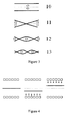
- Figure 3 shows the first natural mode shape of the metal strip 3 profile.
- 10 show the 0-mode movement.
- the dotted line is a center line and the metal strip profile (black line) moves back and forth over the center line.
- 11 shows the 1-mode movement, where the metal strip twists back and forth over the (dotted) center line.
- 12 shows the 2-mode movement, where the metal strip bends back and forth over the (dotted) center line.
- 13 shows the 3-mode movement, where the metal strip, bent twice, moves back and forth over the (dotted) center line. The list of natural modes can be continued further.
- Figure 4 shows the forces from the actuators when the strip is in 0-mode movement.
- the actuators controlling the strip 3 movements are small squares above and below the strip.
- the metal strip 3 In the left figure the metal strip 3 is in the "center” position or the wanted position (the dotted line).
- the metal strip 3 is “below” the center position (vertically displaced) and the arrows symbolize the forces from the actuators (schematically summarized forces from actuators "above” and actuators “below”) on the strip 3.
- the metal strip 3 is “above” the center position and the arrows symbolize the forces from the actuators on the strip 3.
- the arrows also represent a best actuator response for this particular shape.
- Figure 5 shows the forces from the actuators when the strip is in 1-mode movement.
- the actuators controlling the strip 3 movements are small squares above and below the strip.
- the metal strip 3 In the left figure the metal strip 3 is in the "center” position or the wanted position (the dotted line). In the center figure, the metal strip 3 is “twisted” around center position and the arrows symbolize the forces from the actuators on the strip 3. In the right figure, the metal strip 3 is "twisted” in the other direction.
- Figure 6 shows the forces from the actuators when the strip is in 2-mode movement.
- the metal strip 3 In the left figure the metal strip 3 is in the "center" position. In the center figure, the metal strip 3 is bending in one direction and the arrows symbolize the forces from the actuators on the strip 3. In the right figure, the metal strip 3 is bending in the other direction.
- Figure 7 shows the forces from the actuators when the strip is in 3-mode movement.
- the metal strip 3 In the left figure the metal strip 3 is in the "center" position. In the center figure, the metal strip 3 is in 3-mode movement and the arrows symbolize the forces from the actuators on the strip 3. In the right figure, the metal strip 3 is in 3-mode movement in other direction.
- Figure 8 shows the forces from the actuators when the strip is in 4-mode movement.
- the metal strip 3 In the left figure the metal strip 3 is in the "center" position. In the center figure, the metal strip 3 is in 4-mode movement. In the right figure, the metal strip 3 is in the opposite 4-mode movement.
- Figure 4-8 shows different natural mode shapes but the invention is not restricted to using natural mode shapes.
- Figure 9 shows a schematic view of decomposition method in the present invention.
- the left figure 20 shows a schematic view of the moving strip 3 and the position sensors 2.
- the measured movements are decomposed into natural mode shape 21.
- the coefficients (a 0 , a 1 , a 2 , a 3 ) that describe the contribution from each natural mode shape are also determined in the decomposition.
- the coefficients (a 0 , a 1 , a 2 , a 3 ) are time variable.
- the best actuator response for a mode shape can be determined and programmed beforehand.
- the best actuator response for a mode depends on strip dimensions (free length, width and thickness), strip tension and strip speed.
- the idea behind the invention is to express both the strip profile and the total force profile as combinations (linear or other combinations) of the base shapes, using the same number of bases as there are actuators.
- a controller For each base shape, a controller is designed that uses the coefficient of that shape in the series expansion of the current profile (with the profile being approximated using available sensors) as actual value, and the coefficient for the same shape in the series expansion of the force profile as manipulated value.
- the available actuators are then used to synthesize the wanted profile.
- any type of mode shape can be used to decompose the measured strip shape.
- These non-natural mode shapes can be associated with a best actuator 22 response (force profile) in the same way as natural mode shapes are.
- the combination (linear or other combination) of the force profile for any mode (natural or non-natural) is then combined to an actual actuator response 23.
- the aim of the invention is to decompose the strip control into independent one-loop controls, (one for each mode shape.
- the one-loop controls are decoupled from each other and then combined into an actual actuator response 23.
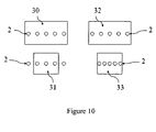
- Figure 10 shows a schematic view of adapting the sensor 2 positions for different strip widths.
- the sensors are placed along the whole width of the strips.
- 33 if the placement of sensors 2 are not adapted to strip width, some will not be able to measure the strip distance 31 and the result will be less exact determining of the strip profile and performance of the damping of the strip. If the placement of sensors 2 is adapted to strip width 33, all sensors 2 will be able to measure the strip distance.
- Another embodiment is to allow the placement or positions of the non-contact actuators to also adapt to the strip width. The positions of sensors could also be placed to avoid measuring the distance at zero deflection of all the different natural modes e.g. avoid having a sensor at the middle of the width of the strip for 1-mode.
Landscapes
- Engineering & Computer Science (AREA)
- Mechanical Engineering (AREA)
- Chemical & Material Sciences (AREA)
- Chemical Kinetics & Catalysis (AREA)
- Materials Engineering (AREA)
- Metallurgy (AREA)
- Organic Chemistry (AREA)
- Coating With Molten Metal (AREA)
- Vibration Prevention Devices (AREA)
- Controlling Rewinding, Feeding, Winding, Or Abnormalities Of Webs (AREA)
Claims (15)
- Verfahren zur Schwingungsdämpfung und Formregelung eines schwebend gelagerten Metallbandes während des kontinuierlichen Transports in einer Verarbeitungsanlage in einer Stahlwalzlinie oder einer Oberflächenbehandlungslinie in einem Stahlwerk, umfassend folgenden Schritt:- Messen des Abstands zu dem Band mittels mehrerer berührungsloser Sensoren,wobei das Verfahren durch folgende weitere Schritte gekennzeichnet ist:- Erzeugen eines Bandprofils aus Abstandsmessungen,- Zerlegen des Bandprofils in eine Kombination aus Modenformen, und- Bestimmen von Koeffizienten für den Beitrag jeder Modenform zu dem gesamten Bandprofil, und- Regeln des Bandprofils mittels mehrerer berührungsloser Aktoren, die über das Band verteilt angeordnet sind, auf der Basis von einer Kombination von Modenformen.
- Verfahren nach Anspruch 1, wobei ein Steuerungsmittel zum Steuern der Aktoren mit vorprogrammierten Steuerungsfunktionen ausgebildet ist, welche eine beste Steuerungsfunktion für jede Modenform umfassen, wobei das Verfahren ferner den Schritt des- Steuerns mehrerer Aktoren durch Gewichten Vorprogrammierter Steuerungsfunktionen mit den Koeffizienten aus der Eigenmodenformzerlegung umfasst.
- Verfahren nach einem beliebigen der Ansprüche 1-2, wobei die Modenformen Eigenmodenformen sind.
- Verfahren nach einem beliebigen der Ansprüche 1-3, wobei das Bandprofil in eine lineare Kombination aus Modenformen zerlegt wird.
- Verfahren nach einem beliebigen der Ansprüche 2-4, wobei das Verfahren ferner den Schritt des Anpassens des Gewichtens vorprogrammierter Steuerungsfunktionen auf der Basis von Eingängen von mindestens einem Prozessparameter wie Bandbreite, Banddicke, Bandspannung und Bandgeschwindigkeit umfasst.
- Verfahren nach einem beliebigen der Ansprüche 1-5, wobei das Verfahren auf der Verwendung derselben Anzahl von berührungslosen Sensoren wie die Anzahl von berührungslosen Aktoren beruht.
- Verfahren nach einem beliebigen der Ansprüche 1-5, wobei das Verfahren auf der Verwendung von mehr berührungslosen Sensoren als berührungslosen Aktoren beruht.
- Verfahren nach einem beliebigen der Ansprüche 1-7, wobei das Verfahren ferner den Schritt des Analysierens der Koeffizienten aus Eigenmodenformzerlegung umfasst.
- System zur Schwingungsdämpfung und/oder Formregelung eines schwebend gelagerten Metallbandes während des kontinuierlichen Transports in einer Fertigungsanlage in einer Stahlwalzlinie oder einer Oberflächenbehandlungslinie in einem Stahlwerk, wobei das System umfasst;- mehrere berührungslose Sensoren, welche den Abstand zu dem Metallband vertikal zu der Bandoberfläche messen,- mehrere berührungslose Aktoren, um das Metallband zu stabilisieren,dadurch gekennzeichnet, dass
das System umfasst: Mittel zum Bestimmen des Bandprofils und Mittel zum Zerlegen des bestimmten Bandprofils in eine Kombination aus Modenformen und zum Bestimmen von Koeffizienten für den Beitrag von jeder Modenform zu dem gesamten Bandprofil sowie Mittel zum Steuern der mehreren Aktoren, die über das Band verteilt angeordnet sind, basierend auf der Kombination aus Modenformen. - System nach Anspruch 9,
dadurch gekennzeichnet, dass
das System Mittel zum Steuern von Aktoren auf der Basis einer vorprogrammierten Steuerungsfunktion für jede Eigenmodenform umfasst und sich die Steuerung der Aktoren einer Kombination aus Steuerungsfunktionen bedient, welche mittels der bestimmten Koeffizienten gewichtet werden. - System nach einem beliebigen der Ansprüche 9-10,
dadurch gekennzeichnet, dass
die Anzahl von berührungslosen Sensoren, welche den Abstand messen, gleich der Anzahl von berührungslosen Aktoren ist. - System nach einem beliebigen der Ansprüche 9-11,
dadurch gekennzeichnet, dass
die Anzahl von berührungslosen Sensoren, welche den Abstand messen, größer als die Anzahl von berührungslosen Aktoren ist. - System nach einem beliebigen der Ansprüche 9-12,
dadurch gekennzeichnet, dass
der berührungslose Sensor, welcher den Abstand zu dem Band misst, in der Nähe des berührungslosen Aktors, welcher die Bewegung des Bandes stabilisiert, angeordnet ist. - System nach einem beliebigen der Ansprüche 9-13, wobei das System das Gewichten von vorprogrammierten Steuerungsfunktionen auf der Basis von Eingängen von Prozessparametern wie Bandbreite und/oder Banddicke anpasst.
- System nach einem beliebigen der Ansprüche 9-14,
dadurch gekennzeichnet, dass
die Aktoren verwendet werden, um die Varianz der Koeffizienten für den Beitrag von jeder Modenform zu dem gesamten Bandprofil zu minimieren.
Applications Claiming Priority (1)
| Application Number | Priority Date | Filing Date | Title |
|---|---|---|---|
| PCT/EP2007/059189 WO2009030269A1 (en) | 2007-09-03 | 2007-09-03 | Mode based metal strip stabilizer |
Publications (2)
| Publication Number | Publication Date |
|---|---|
| EP2190600A1 EP2190600A1 (de) | 2010-06-02 |
| EP2190600B1 true EP2190600B1 (de) | 2012-05-30 |
Family
ID=38875062
Family Applications (1)
| Application Number | Title | Priority Date | Filing Date |
|---|---|---|---|
| EP07803174A Not-in-force EP2190600B1 (de) | 2007-09-03 | 2007-09-03 | Modenformbasierender metallbandstabilisator |
Country Status (8)
| Country | Link |
|---|---|
| US (1) | US8374715B2 (de) |
| EP (1) | EP2190600B1 (de) |
| JP (1) | JP4827988B2 (de) |
| KR (1) | KR101445430B1 (de) |
| CN (1) | CN101795785B (de) |
| BR (1) | BRPI0721971A2 (de) |
| EG (1) | EG25631A (de) |
| WO (1) | WO2009030269A1 (de) |
Families Citing this family (12)
| Publication number | Priority date | Publication date | Assignee | Title |
|---|---|---|---|---|
| EP2437901B1 (de) * | 2009-06-01 | 2013-09-18 | ABB Research Ltd. | Verfahren und system zur schwingungsdämpfung und formsteuerung eines aufgehängten metallbands |
| IT1405694B1 (it) * | 2011-02-22 | 2014-01-24 | Danieli Off Mecc | Dispositivo elettromagnetico per stabilizzare e ridurre la deformazione di un nastro in materiale ferromagnetico e relativo processo |
| WO2012133362A1 (ja) * | 2011-03-30 | 2012-10-04 | シンフォニアテクノロジー株式会社 | 電磁制振装置、電磁制振制御プログラム |
| CN102618813B (zh) * | 2012-02-20 | 2013-11-20 | 宝山钢铁股份有限公司 | 连续处理生产线带钢焊缝跟踪控制方法 |
| CN106488810B (zh) | 2014-07-15 | 2019-10-01 | 诺维尔里斯公司 | 自激第三八度轧机振动的处理阻尼 |
| EP3171995B1 (de) * | 2014-07-25 | 2018-07-11 | Novelis Inc. | Steuerung von ratterschwingungen der dritten oktav eines walzwerks durch verfahrensdämpfung |
| DE102014118946B4 (de) * | 2014-12-18 | 2018-12-20 | Bwg Bergwerk- Und Walzwerk-Maschinenbau Gmbh | Vorrichtung und Verfahren zur kontinuierlichen Behandlung eines Metallbandes |
| DE102016222230A1 (de) * | 2016-08-26 | 2018-03-01 | Sms Group Gmbh | Verfahren und Beschichtungseinrichtung zum Beschichten eines Metallbandes |
| CN109716860B (zh) | 2016-09-27 | 2021-09-24 | 诺维尔里斯公司 | 紧凑的连续退火固溶热处理 |
| CA3211436A1 (en) | 2016-09-27 | 2018-04-05 | Novelis Inc. | Rotating magnet heat induction |
| EP3599038A1 (de) * | 2018-07-25 | 2020-01-29 | Primetals Technologies Austria GmbH | Verfahren und vorrichtung zur ermittlung der seitlichen bandkontur eines laufenden metallbandes |
| CN111926277B (zh) * | 2020-09-07 | 2022-11-01 | 山东钢铁集团日照有限公司 | 一种热镀锌带钢出锌锅后振动抑制装置及抑制方法 |
Family Cites Families (11)
| Publication number | Priority date | Publication date | Assignee | Title |
|---|---|---|---|---|
| US5467655A (en) * | 1991-03-27 | 1995-11-21 | Nippon Steel Corporation | Method for measuring properties of cold rolled thin steel sheet and apparatus therefor |
| JP3002331B2 (ja) * | 1992-06-26 | 2000-01-24 | 株式会社神戸製鋼所 | 鋼板の制振装置 |
| JPH0664806A (ja) * | 1992-08-18 | 1994-03-08 | Nippon Steel Corp | 鋼帯の振動抑制装置 |
| JPH10298727A (ja) * | 1997-04-23 | 1998-11-10 | Nkk Corp | 鋼板の振動・形状制御装置 |
| JP3849362B2 (ja) * | 1999-05-26 | 2006-11-22 | 神鋼電機株式会社 | 鋼板の制振装置 |
| JP4154804B2 (ja) * | 1999-05-26 | 2008-09-24 | 神鋼電機株式会社 | 鋼板の制振装置 |
| TW476679B (en) * | 1999-05-26 | 2002-02-21 | Shinko Electric Co Ltd | Device for suppressing the vibration of a steel plate |
| JP2000345310A (ja) * | 1999-05-31 | 2000-12-12 | Kawasaki Steel Corp | 鋼帯の連続溶融金属めっき設備 |
| FR2797277A1 (fr) * | 1999-08-05 | 2001-02-09 | Lorraine Laminage | Procede et dispositif de realisation en continu d'un revetement de surface metallique sur une tole en defilement |
| US6158260A (en) * | 1999-09-15 | 2000-12-12 | Danieli Technology, Inc. | Universal roll crossing system |
| CN101146925B (zh) | 2005-03-24 | 2012-06-27 | Abb研究有限公司 | 稳定钢板的设备和方法 |
-
2007
- 2007-09-03 EP EP07803174A patent/EP2190600B1/de not_active Not-in-force
- 2007-09-03 BR BRPI0721971-7A patent/BRPI0721971A2/pt not_active Application Discontinuation
- 2007-09-03 WO PCT/EP2007/059189 patent/WO2009030269A1/en not_active Ceased
- 2007-09-03 CN CN2007801004671A patent/CN101795785B/zh not_active Expired - Fee Related
- 2007-09-03 KR KR1020107004660A patent/KR101445430B1/ko not_active Expired - Fee Related
- 2007-09-03 JP JP2010523280A patent/JP4827988B2/ja not_active Expired - Fee Related
-
2010
- 2010-02-09 EG EG2010020211A patent/EG25631A/xx active
- 2010-03-01 US US12/714,886 patent/US8374715B2/en not_active Expired - Fee Related
Also Published As
| Publication number | Publication date |
|---|---|
| US20100161104A1 (en) | 2010-06-24 |
| US8374715B2 (en) | 2013-02-12 |
| EP2190600A1 (de) | 2010-06-02 |
| JP4827988B2 (ja) | 2011-11-30 |
| KR101445430B1 (ko) | 2014-09-26 |
| BRPI0721971A2 (pt) | 2015-07-21 |
| EG25631A (en) | 2012-04-11 |
| WO2009030269A1 (en) | 2009-03-12 |
| CN101795785B (zh) | 2013-09-25 |
| CN101795785A (zh) | 2010-08-04 |
| JP2010537826A (ja) | 2010-12-09 |
| KR20100049629A (ko) | 2010-05-12 |
Similar Documents
| Publication | Publication Date | Title |
|---|---|---|
| EP2190600B1 (de) | Modenformbasierender metallbandstabilisator | |
| EP1871920B1 (de) | Vorrichtung und verfahren zur stabilisierung einer stahlplatte | |
| SE527507C2 (sv) | En anordning och ett förfarande för stabilisering av ett metalliskt föremål samt en användning av anordningen | |
| CA2697194C (en) | Process and hot-dip coating system for stabilizing a strip guided between stripping dies of the hot-dip coating system and provided with a coating | |
| US20170009326A1 (en) | Plate crossbow correction device and plate crossbow correction method | |
| EP3685932A1 (de) | Vorrichtung zur messung der form einer metallplatte, vorrichtung zur verzugskorrektur einer platte, vorrichtung zur kontinuierlichen plattierung und verfahren zur plattenverzugskorrektur für eine metallplatte | |
| CN101627144A (zh) | 在带状载体上连续沉积涂层的方法和设备 | |
| CA3112039A1 (en) | Method for controlling a coating weight uniformity in industrial galvanizing lines | |
| EP2437901B1 (de) | Verfahren und system zur schwingungsdämpfung und formsteuerung eines aufgehängten metallbands | |
| EP1110635A1 (de) | Verfahren und Vorrichtung zur Planheitsregelung | |
| JP2003105515A (ja) | 鋼板形状矯正装置及び方法 | |
| KR20030017111A (ko) | 용융 도금공정에서의 에어나이프 간격 제어장치 | |
| US12442065B2 (en) | System and method for coating of continuous sheets of metal | |
| WO2019106785A1 (ja) | 金属板の板反り矯正装置及び金属板の連続めっき処理設備 | |
| RU2446902C2 (ru) | Способ и система для стабилизации металлической полосы на основе формы нормальных колебаний | |
| JPH1053852A (ja) | 電磁力を利用しためっき付着量調整方法及び装置 | |
| JP4450662B2 (ja) | 鋼板の制振装置 | |
| CA3109674A1 (en) | System and method for coating of continuous sheets of metal |
Legal Events
| Date | Code | Title | Description |
|---|---|---|---|
| PUAI | Public reference made under article 153(3) epc to a published international application that has entered the european phase |
Free format text: ORIGINAL CODE: 0009012 |
|
| 17P | Request for examination filed |
Effective date: 20100406 |
|
| AK | Designated contracting states |
Kind code of ref document: A1 Designated state(s): AT BE BG CH CY CZ DE DK EE ES FI FR GB GR HU IE IS IT LI LT LU LV MC MT NL PL PT RO SE SI SK TR |
|
| AX | Request for extension of the european patent |
Extension state: AL BA HR MK RS |
|
| DAX | Request for extension of the european patent (deleted) | ||
| GRAP | Despatch of communication of intention to grant a patent |
Free format text: ORIGINAL CODE: EPIDOSNIGR1 |
|
| GRAS | Grant fee paid |
Free format text: ORIGINAL CODE: EPIDOSNIGR3 |
|
| GRAA | (expected) grant |
Free format text: ORIGINAL CODE: 0009210 |
|
| AK | Designated contracting states |
Kind code of ref document: B1 Designated state(s): AT BE BG CH CY CZ DE DK EE ES FI FR GB GR HU IE IS IT LI LT LU LV MC MT NL PL PT RO SE SI SK TR |
|
| REG | Reference to a national code |
Ref country code: GB Ref legal event code: FG4D |
|
| REG | Reference to a national code |
Ref country code: CH Ref legal event code: EP |
|
| REG | Reference to a national code |
Ref country code: AT Ref legal event code: REF Ref document number: 559812 Country of ref document: AT Kind code of ref document: T Effective date: 20120615 |
|
| REG | Reference to a national code |
Ref country code: IE Ref legal event code: FG4D |
|
| REG | Reference to a national code |
Ref country code: DE Ref legal event code: R096 Ref document number: 602007023023 Country of ref document: DE Effective date: 20120802 |
|
| REG | Reference to a national code |
Ref country code: NL Ref legal event code: T3 |
|
| REG | Reference to a national code |
Ref country code: LT Ref legal event code: MG4D Effective date: 20120530 |
|
| PG25 | Lapsed in a contracting state [announced via postgrant information from national office to epo] |
Ref country code: SE Free format text: LAPSE BECAUSE OF FAILURE TO SUBMIT A TRANSLATION OF THE DESCRIPTION OR TO PAY THE FEE WITHIN THE PRESCRIBED TIME-LIMIT Effective date: 20120530 Ref country code: FI Free format text: LAPSE BECAUSE OF FAILURE TO SUBMIT A TRANSLATION OF THE DESCRIPTION OR TO PAY THE FEE WITHIN THE PRESCRIBED TIME-LIMIT Effective date: 20120530 Ref country code: CY Free format text: LAPSE BECAUSE OF FAILURE TO SUBMIT A TRANSLATION OF THE DESCRIPTION OR TO PAY THE FEE WITHIN THE PRESCRIBED TIME-LIMIT Effective date: 20120530 Ref country code: LT Free format text: LAPSE BECAUSE OF FAILURE TO SUBMIT A TRANSLATION OF THE DESCRIPTION OR TO PAY THE FEE WITHIN THE PRESCRIBED TIME-LIMIT Effective date: 20120530 Ref country code: IS Free format text: LAPSE BECAUSE OF FAILURE TO SUBMIT A TRANSLATION OF THE DESCRIPTION OR TO PAY THE FEE WITHIN THE PRESCRIBED TIME-LIMIT Effective date: 20120930 |
|
| REG | Reference to a national code |
Ref country code: AT Ref legal event code: MK05 Ref document number: 559812 Country of ref document: AT Kind code of ref document: T Effective date: 20120530 |
|
| PG25 | Lapsed in a contracting state [announced via postgrant information from national office to epo] |
Ref country code: GR Free format text: LAPSE BECAUSE OF FAILURE TO SUBMIT A TRANSLATION OF THE DESCRIPTION OR TO PAY THE FEE WITHIN THE PRESCRIBED TIME-LIMIT Effective date: 20120831 Ref country code: SI Free format text: LAPSE BECAUSE OF FAILURE TO SUBMIT A TRANSLATION OF THE DESCRIPTION OR TO PAY THE FEE WITHIN THE PRESCRIBED TIME-LIMIT Effective date: 20120530 Ref country code: LV Free format text: LAPSE BECAUSE OF FAILURE TO SUBMIT A TRANSLATION OF THE DESCRIPTION OR TO PAY THE FEE WITHIN THE PRESCRIBED TIME-LIMIT Effective date: 20120530 |
|
| PG25 | Lapsed in a contracting state [announced via postgrant information from national office to epo] |
Ref country code: BE Free format text: LAPSE BECAUSE OF FAILURE TO SUBMIT A TRANSLATION OF THE DESCRIPTION OR TO PAY THE FEE WITHIN THE PRESCRIBED TIME-LIMIT Effective date: 20120530 |
|
| PG25 | Lapsed in a contracting state [announced via postgrant information from national office to epo] |
Ref country code: SK Free format text: LAPSE BECAUSE OF FAILURE TO SUBMIT A TRANSLATION OF THE DESCRIPTION OR TO PAY THE FEE WITHIN THE PRESCRIBED TIME-LIMIT Effective date: 20120530 Ref country code: EE Free format text: LAPSE BECAUSE OF FAILURE TO SUBMIT A TRANSLATION OF THE DESCRIPTION OR TO PAY THE FEE WITHIN THE PRESCRIBED TIME-LIMIT Effective date: 20120530 Ref country code: DK Free format text: LAPSE BECAUSE OF FAILURE TO SUBMIT A TRANSLATION OF THE DESCRIPTION OR TO PAY THE FEE WITHIN THE PRESCRIBED TIME-LIMIT Effective date: 20120530 Ref country code: RO Free format text: LAPSE BECAUSE OF FAILURE TO SUBMIT A TRANSLATION OF THE DESCRIPTION OR TO PAY THE FEE WITHIN THE PRESCRIBED TIME-LIMIT Effective date: 20120530 Ref country code: CZ Free format text: LAPSE BECAUSE OF FAILURE TO SUBMIT A TRANSLATION OF THE DESCRIPTION OR TO PAY THE FEE WITHIN THE PRESCRIBED TIME-LIMIT Effective date: 20120530 Ref country code: AT Free format text: LAPSE BECAUSE OF FAILURE TO SUBMIT A TRANSLATION OF THE DESCRIPTION OR TO PAY THE FEE WITHIN THE PRESCRIBED TIME-LIMIT Effective date: 20120530 |
|
| PG25 | Lapsed in a contracting state [announced via postgrant information from national office to epo] |
Ref country code: PL Free format text: LAPSE BECAUSE OF FAILURE TO SUBMIT A TRANSLATION OF THE DESCRIPTION OR TO PAY THE FEE WITHIN THE PRESCRIBED TIME-LIMIT Effective date: 20120530 Ref country code: PT Free format text: LAPSE BECAUSE OF FAILURE TO SUBMIT A TRANSLATION OF THE DESCRIPTION OR TO PAY THE FEE WITHIN THE PRESCRIBED TIME-LIMIT Effective date: 20121001 |
|
| PLBE | No opposition filed within time limit |
Free format text: ORIGINAL CODE: 0009261 |
|
| STAA | Information on the status of an ep patent application or granted ep patent |
Free format text: STATUS: NO OPPOSITION FILED WITHIN TIME LIMIT |
|
| PG25 | Lapsed in a contracting state [announced via postgrant information from national office to epo] |
Ref country code: ES Free format text: LAPSE BECAUSE OF FAILURE TO SUBMIT A TRANSLATION OF THE DESCRIPTION OR TO PAY THE FEE WITHIN THE PRESCRIBED TIME-LIMIT Effective date: 20120910 Ref country code: MC Free format text: LAPSE BECAUSE OF NON-PAYMENT OF DUE FEES Effective date: 20120930 |
|
| REG | Reference to a national code |
Ref country code: CH Ref legal event code: PL |
|
| 26N | No opposition filed |
Effective date: 20130301 |
|
| REG | Reference to a national code |
Ref country code: IE Ref legal event code: MM4A |
|
| REG | Reference to a national code |
Ref country code: DE Ref legal event code: R097 Ref document number: 602007023023 Country of ref document: DE Effective date: 20130301 |
|
| PG25 | Lapsed in a contracting state [announced via postgrant information from national office to epo] |
Ref country code: BG Free format text: LAPSE BECAUSE OF FAILURE TO SUBMIT A TRANSLATION OF THE DESCRIPTION OR TO PAY THE FEE WITHIN THE PRESCRIBED TIME-LIMIT Effective date: 20120830 Ref country code: LI Free format text: LAPSE BECAUSE OF NON-PAYMENT OF DUE FEES Effective date: 20120930 Ref country code: CH Free format text: LAPSE BECAUSE OF NON-PAYMENT OF DUE FEES Effective date: 20120930 Ref country code: IE Free format text: LAPSE BECAUSE OF NON-PAYMENT OF DUE FEES Effective date: 20120903 |
|
| PG25 | Lapsed in a contracting state [announced via postgrant information from national office to epo] |
Ref country code: MT Free format text: LAPSE BECAUSE OF FAILURE TO SUBMIT A TRANSLATION OF THE DESCRIPTION OR TO PAY THE FEE WITHIN THE PRESCRIBED TIME-LIMIT Effective date: 20120530 |
|
| PG25 | Lapsed in a contracting state [announced via postgrant information from national office to epo] |
Ref country code: TR Free format text: LAPSE BECAUSE OF FAILURE TO SUBMIT A TRANSLATION OF THE DESCRIPTION OR TO PAY THE FEE WITHIN THE PRESCRIBED TIME-LIMIT Effective date: 20120530 |
|
| PG25 | Lapsed in a contracting state [announced via postgrant information from national office to epo] |
Ref country code: LU Free format text: LAPSE BECAUSE OF NON-PAYMENT OF DUE FEES Effective date: 20120903 |
|
| PG25 | Lapsed in a contracting state [announced via postgrant information from national office to epo] |
Ref country code: HU Free format text: LAPSE BECAUSE OF FAILURE TO SUBMIT A TRANSLATION OF THE DESCRIPTION OR TO PAY THE FEE WITHIN THE PRESCRIBED TIME-LIMIT Effective date: 20070903 |
|
| REG | Reference to a national code |
Ref country code: FR Ref legal event code: PLFP Year of fee payment: 10 |
|
| REG | Reference to a national code |
Ref country code: FR Ref legal event code: PLFP Year of fee payment: 11 |
|
| REG | Reference to a national code |
Ref country code: FR Ref legal event code: PLFP Year of fee payment: 12 |
|
| PGFP | Annual fee paid to national office [announced via postgrant information from national office to epo] |
Ref country code: NL Payment date: 20180919 Year of fee payment: 12 |
|
| REG | Reference to a national code |
Ref country code: DE Ref legal event code: R081 Ref document number: 602007023023 Country of ref document: DE Owner name: ABB SCHWEIZ AG, CH Free format text: FORMER OWNER: ABB RESEARCH LTD., ZUERICH, CH |
|
| REG | Reference to a national code |
Ref country code: GB Ref legal event code: 732E Free format text: REGISTERED BETWEEN 20200206 AND 20200212 |
|
| REG | Reference to a national code |
Ref country code: NL Ref legal event code: MM Effective date: 20191001 |
|
| PG25 | Lapsed in a contracting state [announced via postgrant information from national office to epo] |
Ref country code: NL Free format text: LAPSE BECAUSE OF NON-PAYMENT OF DUE FEES Effective date: 20191001 |
|
| PGFP | Annual fee paid to national office [announced via postgrant information from national office to epo] |
Ref country code: IT Payment date: 20210922 Year of fee payment: 15 Ref country code: FR Payment date: 20210921 Year of fee payment: 15 |
|
| PGFP | Annual fee paid to national office [announced via postgrant information from national office to epo] |
Ref country code: DE Payment date: 20210920 Year of fee payment: 15 Ref country code: GB Payment date: 20210920 Year of fee payment: 15 |
|
| REG | Reference to a national code |
Ref country code: DE Ref legal event code: R119 Ref document number: 602007023023 Country of ref document: DE |
|
| GBPC | Gb: european patent ceased through non-payment of renewal fee |
Effective date: 20220903 |
|
| PG25 | Lapsed in a contracting state [announced via postgrant information from national office to epo] |
Ref country code: FR Free format text: LAPSE BECAUSE OF NON-PAYMENT OF DUE FEES Effective date: 20220930 Ref country code: DE Free format text: LAPSE BECAUSE OF NON-PAYMENT OF DUE FEES Effective date: 20230401 |
|
| PG25 | Lapsed in a contracting state [announced via postgrant information from national office to epo] |
Ref country code: IT Free format text: LAPSE BECAUSE OF NON-PAYMENT OF DUE FEES Effective date: 20220903 Ref country code: GB Free format text: LAPSE BECAUSE OF NON-PAYMENT OF DUE FEES Effective date: 20220903 |