EP2190608B1 - Anordnung zur formung einer dosenunterseite - Google Patents
Anordnung zur formung einer dosenunterseite Download PDFInfo
- Publication number
- EP2190608B1 EP2190608B1 EP08794692.7A EP08794692A EP2190608B1 EP 2190608 B1 EP2190608 B1 EP 2190608B1 EP 08794692 A EP08794692 A EP 08794692A EP 2190608 B1 EP2190608 B1 EP 2190608B1
- Authority
- EP
- European Patent Office
- Prior art keywords
- assembly
- bottom forming
- clamp ring
- constructed
- cylinder housing
- Prior art date
- Legal status (The legal status is an assumption and is not a legal conclusion. Google has not performed a legal analysis and makes no representation as to the accuracy of the status listed.)
- Not-in-force
Links
- 125000006850 spacer group Chemical group 0.000 claims description 15
- 229910001315 Tool steel Inorganic materials 0.000 claims description 8
- 229910052782 aluminium Inorganic materials 0.000 claims description 6
- XAGFODPZIPBFFR-UHFFFAOYSA-N aluminium Chemical compound [Al] XAGFODPZIPBFFR-UHFFFAOYSA-N 0.000 claims description 6
- 230000002093 peripheral effect Effects 0.000 claims description 6
- JOYRKODLDBILNP-UHFFFAOYSA-N Ethyl urethane Chemical compound CCOC(N)=O JOYRKODLDBILNP-UHFFFAOYSA-N 0.000 claims description 5
- 239000000919 ceramic Substances 0.000 claims description 5
- 238000004891 communication Methods 0.000 claims description 3
- 239000002131 composite material Substances 0.000 claims description 3
- IOVCWXUNBOPUCH-UHFFFAOYSA-M Nitrite anion Chemical compound [O-]N=O IOVCWXUNBOPUCH-UHFFFAOYSA-M 0.000 claims description 2
- 239000000463 material Substances 0.000 description 12
- 230000000712 assembly Effects 0.000 description 9
- 238000000429 assembly Methods 0.000 description 9
- 230000005484 gravity Effects 0.000 description 7
- 238000004519 manufacturing process Methods 0.000 description 7
- 230000008901 benefit Effects 0.000 description 5
- 230000009471 action Effects 0.000 description 4
- 239000002826 coolant Substances 0.000 description 4
- 238000007667 floating Methods 0.000 description 3
- 239000002783 friction material Substances 0.000 description 3
- 239000007787 solid Substances 0.000 description 3
- 235000013361 beverage Nutrition 0.000 description 2
- 238000004140 cleaning Methods 0.000 description 2
- 238000010276 construction Methods 0.000 description 2
- 230000000694 effects Effects 0.000 description 2
- 230000006872 improvement Effects 0.000 description 2
- 239000003562 lightweight material Substances 0.000 description 2
- 238000000034 method Methods 0.000 description 2
- 230000008569 process Effects 0.000 description 2
- 229910002651 NO3 Inorganic materials 0.000 description 1
- NHNBFGGVMKEFGY-UHFFFAOYSA-N Nitrate Chemical compound [O-][N+]([O-])=O NHNBFGGVMKEFGY-UHFFFAOYSA-N 0.000 description 1
- 229910000831 Steel Inorganic materials 0.000 description 1
- 230000009286 beneficial effect Effects 0.000 description 1
- 230000008859 change Effects 0.000 description 1
- 239000011248 coating agent Substances 0.000 description 1
- 238000000576 coating method Methods 0.000 description 1
- 125000004122 cyclic group Chemical group 0.000 description 1
- 230000001351 cycling effect Effects 0.000 description 1
- 239000000975 dye Substances 0.000 description 1
- 238000010409 ironing Methods 0.000 description 1
- 230000013011 mating Effects 0.000 description 1
- 229910052751 metal Inorganic materials 0.000 description 1
- 239000002184 metal Substances 0.000 description 1
- 230000036316 preload Effects 0.000 description 1
- 238000007665 sagging Methods 0.000 description 1
- 239000010959 steel Substances 0.000 description 1
- 230000037303 wrinkles Effects 0.000 description 1
Images





Classifications
-
- B—PERFORMING OPERATIONS; TRANSPORTING
- B21—MECHANICAL METAL-WORKING WITHOUT ESSENTIALLY REMOVING MATERIAL; PUNCHING METAL
- B21D—WORKING OR PROCESSING OF SHEET METAL OR METAL TUBES, RODS OR PROFILES WITHOUT ESSENTIALLY REMOVING MATERIAL; PUNCHING METAL
- B21D22/00—Shaping without cutting, by stamping, spinning, or deep-drawing
- B21D22/20—Deep-drawing
- B21D22/30—Deep-drawing to finish articles formed by deep-drawing
Definitions
- the present invention relates generally to assemblies used in the manufacture of metal containers. Particularly, the invention relates to a bottom forming assembly used in the drawing and forming of the bottom portions of two piece steel and aluminum cans.
- the can bottom forming assembly of the present invention is an improvement of the bottom formers disclosed in U.S. Patent No. 4,930,330 ('330 Patent) to Weishalla, entitled Double Action Bottom Former, and U.S. Patent No. 6,490,904 B1 ('904 Patent) to Zauhar, entitled Double Action Bottom Former for High Cyclic Operation, both owned by the Assignee of the present invention.
- the bottom formers of the '330 and '904 Patents, incorporated by reference herein, are constructed and arranged for cooperating use with a can bodymaker and specifically, the bodymaker punch carrying the can bodies.
- the '330 Patent and the '904 Patent disclose dome plug positioning structures for bottom forming assemblies.
- the present invention provides further improvements for can bottom forming assemblies.
- the '330 and '904 Patents disclose can bottom forming processes including the action of the punch or ram of a can bodymaker assembly with respect to a bottom forming assembly.
- Bottom forming assemblies are typically constructed and arranged to cooperate with bodymaker assemblies.
- the bottom former receives can bodies on the rapid cycling bodymaker punch and forms two piece can body bottoms through a drawing and final forming process utilizing a clamp ring and dome plug.
- clamp ring is also known in the industry as a pressure ring, guide ring or outer die.
- dome plug is also known in the industry as an inner die or dome post. The specific manufacture of cans, beverage or food, may determine the use of the particular term.
- Document US 2006/225479 A1 discloses a can bottom forming assembly comprising an housing assembly with an outer housing, a cylinder housing assembly, a clamp ring assembly having biasing means to float a clamp ring, a domer plug assembly, a compressible spring member, a piston assembly as well as means to attach the can bottom assembly to a bodymaker assembly.
- the bottom forming assemblies of the present invention provide a compact, lightweight, easy to maintain and service bottom forming assembly having a novel arrangement of components to provide the requisite clamp ring pressure and improving the centering and biasing control of the clamp ring.
- the present invention provides a bottom forming assembly which is an easy to service doming assembly which floats a clamp ring to respond to variations in bodymaker punch locations.
- the bottom forming assembly of the invention includes a configuration which provides increased piston size, increased clamp ring pressure, a lightweight construction and an improved biasing means to float the clamp ring.
- the walls of the can body are formed in a bodymaker assembly, the operation of which is described in the '330 and '904 Patents which are incorporated by reference herein.
- a punch i.e. from the bodymaker structure, carries the can body out of the tool pack to the clamp ring of the bottom forming assembly.
- the clamp ring is constructed and arranged to float to thereby guide the punch to the center of the doming assembly and to re-center upon the exit of the punch. As the punch travels into the bottom forming assembly, the clamp ring structure axially centers the punch with the dome plug.
- the clamp ring When making two piece beverage cans, the clamp ring is used as a draw ring to apply pressure on the can material as it flows into the dome, thus controlling the material flow and preventing wrinkles.
- the clamp ring acts as a guide member to align grooves in the punch with mating grooves in the inner die or dome plug. With thinner materials being used to make cans, a strong can bottom profile is desired. In order to make such a bottom profile, a clamp ring must be able to apply a specified pressure on the can material.
- An embodiment of the bottom forming assembly of the present invention is comprised of a clamp ring assembly, a dome plug, an annular spring member, an outer housing assembly, a piston assembly and a cylinder housing assembly.
- a cover chamber is located at the end of the bottom forming assembly which defines a pressure build-up and release chamber.
- the assembly is preferably mounted to a bodymaker using a mounting flange, at least one spacer member, the outer and cylinder housings and tension bolts.
- the assembly is constructed and arranged to have an increased piston diameter and larger spring surface compared to prior art assemblies and provides a compact, lightweight structure.
- the clamp ring is floated using a plurality of hardened pins which are under air pressure force.
- the can bottom forming assembly of the present invention provides a compact, lightweight bottom forming assembly which provides a floated clamp ring to center the ram or punch of a bodymaker and which has a center of gravity relatively closer to the tool pack. By increasing the piston size and spring diameter, a greater clamp ring pressure is attained. This arrangement of components also provides a light, compact bodymaker structure having a center of gravity closer to the tool pack and punch interface.
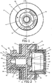
- bottom forming assembly 10 is shown having outer housing assembly 11 and cylinder housing assembly 20.
- Clamp ring retainer assembly 40 having biasing means 44 shown at the front of the bottom forming assembly and holding floating clamp ring 43.
- Clamp ring retainer assembly 40 is shown held in place by locking device 85.
- the clamp ring retainer assembly 40 is shown positioned adjacent dome plug assembly 90 and abutting outer housing assembly 11.
- Outer housing assembly 11 is shown having bushing 13 which cooperates with cylinder housing assembly 20.
- Cylinder housing assembly is shown joined to dome plug assembly 90 via fastener 32.
- Push rods 60 are shown and which extend from clamp ring 43 and through cylinder housing assembly 20. Each push rod 60 is shown terminating at piston assembly 80 which slidably moves within chamber 69 via bushing 22.
- Dome plug assembly 90 is shown having body 91 and defining vent cavity 92. Cavity 92 is shown in communication with cavity 36 and drain channel 50 of cylinder housing assembly 20.
- Cover chamber 65 is shown forming chamber 68 and is shown attached to the end of the bottom forming assembly 10, namely to cylinder housing 20. Cover chamber 65 is shown having oil inlet aperture 27, coolant inlet 28, and drain 29.
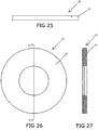
- the bottom forming assembly of this invention is constructed and arranged to be mounted to a bodymaker door using mounting flange 35, spacer 52 and a plurality, i.e. ten, tension bolts 19 having hex-heads 39, as shown in Figure 24 .
- Tensions bolts 19 extend through apertures in spring end plate 75, spring 57, cylinder housing 20, outer housing 11, spacer 52, the bodymaker door (not shown) and are secured on the other side of the bodymaker door structure.
- Bushing 13 is preferably constructed of a polymeric composite material, such as those manufactured by HyComp, Inc., or similar polymeric, greaseless, self-lubricating materials.
- Outer housing assembly 11 is preferably constructed of tool steel or a like hard material.
- the punch of the bodymaker which carries the can body to the bottom former assembly 10 strikes the can body against the clamp ring assembly and transfers force on the piston assembly and spring member.
- the die plug 90 is attached to the cylinder housing 20, which causes spring 57 to be compressed. It is desirable to provide an annular spring structure having a large diameter to provide an increased force absorbing area to absorb the requisite clamp ring pressure to form the desired can bottom profile.
- the piston assembly 70 moves within the cylinder housing 20 and compresses the spring member 57.
- an overtravel measuring device shown as element 94 in Figure 4 of the 11/346,132 Application, which is fully incorporated by reference herein
- outer housing assembly 11 to measure the travel movement within the bottom forming assembly and to make adjustments or replacements if necessary, for example changing the spring member or adjusting the bottom former position if excessive overtravel is detected.
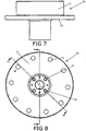
- Figures 7-10 show cylinder housing 20 having body 21 which has a generally circular cross-section, as shown in Figure 8 .
- apertures 25 for receiving tension bolts are shown located radially around cylinder housing body 21.
- cylinder housing body 21 has two opposing, outwardly extending cylindrical ends, 33 and 34, each forming a cavity 36 and 37, respectively.
- Bushing 22 is shown located within cavity 37 and thereby cooperating with cylinder housing body 21.
- Bushing 22 is preferably made of a ceramic or like low friction material. As shown in Figure 2 , bushing 22 provides a low friction surface for slidably engaging piston seal 93 and annular piston ring 83.
- Cylinder housing body 21 is shown having opposing axially aligned cylinders 33 and 34 separated by a circular wall having an annular peripheral ledge 38 which extends outward from cylinders 33 and 34.
- First cylindrical end 33 has a diameter D1 and second cylindrical end 34 has a diameter D2, which is larger than D1.
- Plug body 91 of domer die plug 90 is axially mounted to the first cylindrical end 33 of cylinder housing assembly 20 and which reciprocates within bushing 13.
- Outer plate or wall of cylindrical housing 20 has a peripheral ledge 38, defined by second cylindrical end 34 having a diameter D 3 and on which annular spring member 57 is positioned.
- Cover member 65 is mounted to second cylindrical end 34, having diameter D 2 .
- Piston assembly 80 reciprocates within ceramic bushing 22 in cavity 37 of second cylindrical end 34 of cylindrical housing 20.
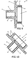
- Cylinder housing body 21 is further shown in Figures 8 and 10 to have push rod seals 23, apertures 30 to receive a push rod 60, and bushing 24 and sleeve 26 within apertures 30.
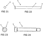
- Push rods 60 shown in Figures 2 , 21 and 22 are constructed and arranged to be slidably engaged with the cylinder housing body 21 through apertures 30.
- drain or channel 50 is shown located in body 21 to aid the passage of air for pressure release resulting from the striking of the dome plug.
- cavity 92 of dome plug assembly 90, cavity 36 and drain 50 of cylinder housing assembly 20 are shown in communication with each other and thus forming a pressure release channel through the bottom forming assembly 10.
- Cylinder housing assembly 20 is preferably constructed of tool steel to provide a bottom former assembly with a center of gravity closer to the mounting apparatus on the bodymaker.
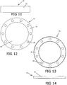
- Figures 11 and 12 show spring member 57 having body 58 having radial apertures 59 and central aperture 64.
- Aperture 64 is shown centrally disposed in spring member body 58 and is constructed to fit around portion 34 of cylinder housing assembly 20.
- Spring member 57 is constructed to be positioned between ledge 38 of cylinder housing 20 and spring end plate 75.
- Spring member 57 is preferably constructed of urethane or a like compressible material.
- Apertures 59 are constructed and arranged to receive tension bolts 19 extending therethrough, which are shown in Figures 23-24 having hex heads 39. It has been found that large piston size and spring diameter are optimal for absorbing forces in the bottom former environment when increasing clamp ring pressure. Increasing the spring diameter and positioning the spring around the cylinder housing (within which the piston reciprocates) also provides an assembly having a compact structure.
- Figures 13 and 14 show spring end plate 75, having a generally circular body 76 and apertures 77 for receiving tension bolts 19 therethrough.
- Spring 57 is shown in Figure 2 , disposed between cylinder housing 20 and spring end plate 75.
- Tension bolts 19 are shown extending through spring end plate 75, spring 57 and cylinder housing 20 and fastening to outer housing 11.
- spring member 57 has an annular configuration and is disposed around cylindrical end 34, between wall 38 of cylinder housing 20 and spring end plate 75. As also shown in Figure 2 , cylindrical end 33 of cylinder housing 20 slidably moves within bushing 13 when force is exerted upon dome plug assembly 90. Thus, spring member 57 is compressed, thereby, absorbing force.
- Clamp ring 43 is constructed and arranged to abut push rods 60. Push rods terminate at piston assembly 80.
- Piston assembly 80 is shown in Figure 2 comprised of annular piston wall 81, annular piston ring 83 and piston end member 79.
- Mounting flange 35 is shown in Figure 2 and is further shown in Figures 10 and 11 of the 11/346,132 Application , which is fully incorporated by reference herein. Tension bolts 19 and mounting flange 35 are utilized to mount the bottom forming assembly 10 to a bodymaker.
- the mounting flange 35 is preferably constructed of tool steel or a like material.
- FIGS 15-17 oil inlet aperture 27, coolant inlet 28 and drain 29 are shown disposed in cylinder housing body 21.
- Figures 8 and 9 are sectional views of the cylinder housing assembly 20, showing body 21 drains 29 and 50 being disposed in body 21.
- Cylinder housing body 21 is shown generally cylindrical in shape and is preferably made of tool steel.
- FIGS 15-17 show cover chamber assembly 65 having body 66.
- Body 66 is shown having cleaning port 29 and pressurized air line aperture 67.
- cover chamber 65 is shown disposed at the end of bottom forming assembly 10 and defining chamber 68.
- the air inside the bottom former is compressed due to the punch of the ram and the stroke of the piston assembly within the bottom former.
- Chamber 68 and pressurized air line aperture 67 provides release for this built-up pressure.
- Cleaning port 29 can be opened to clean or blow out excess coolant and air.
- Cover chamber assembly 65 is preferably constructed of aluminum or like lightweight material to reduce mass and to effect the center of gravity of the bottom former.
- Figures 18-20 show locking device 85 having body 86 and teeth 87. Apertures 88 are shown and are for securement of the locking device 85 to the locking nut 84 shown in Figure 2 . As discussed above, teeth 87 of locking device body 86 cooperate with teeth 42 of clamp ring retainer body 41 to secure the clamp ring retainer assembly in place.
- push rods 60 have an elongated cylindrical body 61 with opposing and different ends 62 and 63. Specifically, a capped end 62 is provided to permit the push rods to be placed within the bottom former assembly 10 in the proper manner and to prevent push rod seal damage.
- Figures 28-31 show clamp ring retainer assembly 40 having body 41 with peripheral cavities 51 to hold biasing means 44 which float the clamp ring in the bottom forming assembly 10.
- Clamp ring 43 is shown in use with clamp ring retainer assembly 40 in Figure 2 .
- Teeth 42 are shown peripherally disposed on body 41 and are constructed and arranged to communicate with teeth 87 of locking device 85 (shown in Figure 18 ) to secure and position the clamp ring retainer device.
- Biasing means 44 are shown comprising cooperating elements, namely, ball member 45, first cap member 46, spring member 47, second cap member 48 and clip member 49, which fit into cavities 51.
- spring member 47 is constructed of urethane or a like compressible material.
- each cavity 51 is formed to receive the ball member 45, first cap member 46, compressible spring member 47, second cap member 48 and clip member 49.
- Figures 28 and 29 particularly show the spherical ball members 45, cooperating and formed first cap member 46, compressible and cooperating compressible spring member 47 having a centrally disposed protrusion, second cap member 48 and clip member 49.
- Clip member 49 is shown disposed at the top of the biasing means 44 and is constructed to snap into the groove shown at the top of cavity 51 of Figure 31 .
- This arrangement compresses the spring member 47 to provide a sufficient preload pressure on the ball member 45 to center and control the float of the clamp ring.
- the ball member preferably slightly extends from clamp ring retainer body 41 for contact with clamp ring 43.
- This biasing structure 44 comprising the cooperating elements described, i.e., spherical ball members 45 (nitrite) and compressible springs 47 (urethane), provide a peripherally acting biasing means which float the clamp ring 43.
- the floating clamp ring In use, when the bodymaker punch and can body hits the clamp ring, the floating clamp ring is permitted to center itself around the punch. As the punch continues to travel into the bottom forming assembly, the clamp ring will move the punch so that it and the can body are centered with respect to the bottom forming assembly. The can body is then guided to the domer die plug, where the can bottom is set. The punch forces the can body into the front end of the bottom forming assembly which contains a mold of the desired shape for the can bottom, thereby setting the dome on the bottom of a two piece can. Since the punch is centered with respect to the doming assembly, the incidence of producing can deformities, i.e., split domes, is reduced, the intended base profile is kept square and ram whip and its effects are reduced.
Landscapes
- Engineering & Computer Science (AREA)
- Mechanical Engineering (AREA)
- Shaping Metal By Deep-Drawing, Or The Like (AREA)
- Pressure Vessels And Lids Thereof (AREA)
Claims (10)
- Dosenbodenformungsvorrichtung (10) zum Formen des Bodens eines Dosenkörpers und zum Anbringen an einen Körperhersteller, welcher einen Stempel aufweist, wobei die Bodenformungsvorrichtung folgendes aufweist:a) eine Gehäuseanordnung, welche ein äußeres Gehäuse (11), ein Zylindergehäuse (20) und eine Deckelkammer (65) aufweist, wobei das Zylindergehäuse (20) für ein gleitendes Eingreifen innerhalb des äußeren Gehäuses (11) konstruiert und angeordnet ist, wobei das Zylindergehäuse (20) einander gegenüberliegende axial ausgerichtete Zylinder (33, 34) aufweist, welche durch eine kreisscheibenförmige Wand mit einem kranzförmigen umlaufenden Absatz (38), der sich außerhalb der axial ausgerichtete Zylinder (33, 34) erstreckt, voneinander getrennt sind,b) eine Klemmringaufnahmeanordnung (40), welche Vorspannmittel zum beweglichen Lagern eines Klemmrings (43) aufweisen, wobei die Klemmringaufnahmeanordnung (40) so konstruiert und angeordnet ist, dass sie teilweise innerhalb des äußeren Gehäuses (11) positioniert ist,c) einen Klemmring (43) und einen wölbungsbildenden Stempelpfropfen (90) zur Berührung mit dem Dosenboden,d) eine Kolbenanordnung (80), die mit dem wölbungsbildenden Stempelpfropfen (90) zusammenwirkt,e) ein ringförmiges komprimierbares Federelement (57) das zur Anordnung auf dem Zylindergehäuse (20) konstruiert und angeordnet ist, um Bewegung des Zylindergehäuses (20) relativ zum äußeren Gehäuse (11) zu absorbieren, undf) Mittel zum Anbringen der Bodenformungsvorrichtung an eine Körperherstellungsanordnung, wobei die Mittel zum Anbringen einen Montageflansch (35), mindestens einen Spannungsbolzen (19) und mindestens ein Abstandhalterelement (52) aufweisen, und wobei eine Federplatte (75) auf Abstand von dem kranzförmigen Absatz (38) gehalten wird, und wobei der Spannungsbolzen (19) sich durch die Federplatte (75), das ringförmige Federelement (57), den Abstandhalter (52) und das äußere Gehäuse (11) erstreckt.
- Dosenbodenformungsvorrichtung gemäß Anspruch 1, wobei die Vorspannmittel der Klemmringaufnahmeanordnung (40) mehrere Vorspannung erzeugende Elemente (44) aufweisen, welche jeweils ein komprimierbares Federlement (47) und ein hiermit zusammenwirkendes starres Kugelelement (45) aufweisen, wobei jedes der Kugelelemente im wesentlichen eine Kugelform besitzt.
- Dosenbodenformungsvorrichtung gemäß Anspruch 1, wobei ein ringförmiges Federlement (57) sich auf dem kranzförmigen Absatz (38) abstützend und um einen der Zylinder (34) montiert ist.
- Dosenbodenformungsvorrichtung gemäß Anspruch 2, wobei das Federlement (47) der Vorspannmittel aus Urethan konstruiert ist, und das Kugelelement (45) aus Nitrit konstruiert ist.
- Dosenbodenformungsvorrichtung gemäß Anspruch 1, welches ferner eine Büchse (13) aus einem Polymerverbundwerkstoff aufweist, und wobei das Zylindergehäuse (20) sich in dem äußeren Gehäuse (11) über die Büchse (13) bewegt.
- Dosenbodenformungsvorrichtung gemäß Anspruch 1, welches ferner eine keramische Büchse (22) aufweist, und wobei sich die Kolbenansordnung (80) innerhalb des Zylindergehäuses (20) über die keramische Hülse bewegt.
- Dosenbodenformungsvorrichtung gemäß Anspruch 1, wobei die Deckelkammer (65) eine Öffnung aufweist, um eine Leitung für Druckluft aufzunehmen.
- Dosenbodenformungsvorrichtung gemäß Anspruch 1, wobei das ringförmige Federlement (57) aus Urethan konstruiert ist.
- Dosenbodenformungsvorrichtung gemäß Anspruch 1, wobei die Deckelkammer (65) aus Aluminium konstruiert ist, und wobei das äußere Gehäuse (11), die Klemmringaufnahmeanordnung (40), das Zylindergehäuse (20) und die Kolbenanordnung (80) aus Werkzeugstahl konstruiert sind.
- Dosenbodenformungsvorrichtung gemäß Anspruch 1, wobei die Anordnung ferner Verriegelungsmittel (85) aufweist, die dazu konstruiert und angeordnet sind, die Klemmringaufnahmeanordnung (40) zu sichern.
Applications Claiming Priority (2)
| Application Number | Priority Date | Filing Date | Title |
|---|---|---|---|
| US11/904,861 US7526937B2 (en) | 2006-02-02 | 2007-09-28 | Can bottom forming assembly |
| PCT/US2008/008959 WO2009042009A1 (en) | 2007-09-28 | 2008-07-24 | Can bottom forming assembly |
Publications (3)
| Publication Number | Publication Date |
|---|---|
| EP2190608A1 EP2190608A1 (de) | 2010-06-02 |
| EP2190608A4 EP2190608A4 (de) | 2014-01-01 |
| EP2190608B1 true EP2190608B1 (de) | 2018-05-02 |
Family
ID=39027818
Family Applications (1)
| Application Number | Title | Priority Date | Filing Date |
|---|---|---|---|
| EP08794692.7A Not-in-force EP2190608B1 (de) | 2007-09-28 | 2008-07-24 | Anordnung zur formung einer dosenunterseite |
Country Status (6)
| Country | Link |
|---|---|
| US (1) | US7526937B2 (de) |
| EP (1) | EP2190608B1 (de) |
| JP (1) | JP5400049B2 (de) |
| BR (1) | BRPI0807502B1 (de) |
| RU (1) | RU2448800C2 (de) |
| WO (1) | WO2009042009A1 (de) |
Families Citing this family (7)
| Publication number | Priority date | Publication date | Assignee | Title |
|---|---|---|---|---|
| ES2354520T3 (es) * | 2007-08-07 | 2011-03-15 | E. W. MENN GMBH & CO. KG | Máquina laminadora de perfiles. |
| US8713980B2 (en) * | 2011-05-31 | 2014-05-06 | Stolle Machinery Company, Llc | Automatic domer positioning in a bodymaker |
| WO2017040780A1 (en) * | 2015-09-02 | 2017-03-09 | Pride Engineering, Llc | Floating clamp ring assembly |
| US10441992B2 (en) * | 2017-01-20 | 2019-10-15 | Pride Engineering, Llc | Can bottom former assembly |
| GB2561859B (en) * | 2017-04-25 | 2019-04-24 | Crown Packaging Technology Inc | Can base forming |
| JP7308720B2 (ja) * | 2019-10-29 | 2023-07-14 | アルテミラ製缶株式会社 | 缶成形装置のドーマー機構、および缶成形装置 |
| US12544823B2 (en) * | 2022-12-20 | 2026-02-10 | Stolle Machinery Company, Llc | Ram support assembly for a can bodymaker and can bodymaker including same |
Family Cites Families (16)
| Publication number | Priority date | Publication date | Assignee | Title |
|---|---|---|---|---|
| US2038466A (en) | 1933-11-09 | 1936-04-21 | Paul R Yates | Flexible coupling |
| US3835666A (en) * | 1973-08-30 | 1974-09-17 | J Hoffman | Versatile tool holder |
| SU566655A2 (ru) * | 1976-01-04 | 1977-07-30 | Предприятие П/Я В-2126 | Станок дл обжима и закатки горловин полых цилиндрических изделий |
| US4324124A (en) | 1978-04-26 | 1982-04-13 | National Can Corporation | Stripper assembly for bodymaker |
| SU880584A1 (ru) * | 1978-05-10 | 1981-11-15 | Московский Ордена Трудового Красного Знамени Институт Стали И Сплавов | Способ обкатки концов трубчатых заготовок |
| US4257254A (en) * | 1979-03-16 | 1981-03-24 | Teledyne Industries, Inc. | Adapter cushion |
| US4930330A (en) * | 1989-07-27 | 1990-06-05 | Pride Machine Inc. | Double action bottom former |
| RU2009748C1 (ru) * | 1992-06-29 | 1994-03-30 | Губин Алексей Иванович | Способ изготовления баллона |
| RU2065793C1 (ru) * | 1993-04-28 | 1996-08-27 | Владимир Владимирович Павелко | Штамп для изготовления фигурных конических деталей |
| US5797292A (en) * | 1996-05-01 | 1998-08-25 | Coors Brewing Company | Domer apparatus for a can body making apparatus |
| GB9609407D0 (en) * | 1996-05-04 | 1996-07-10 | Metal Box Plc | Base forming station |
| GB9719549D0 (en) * | 1997-09-16 | 1997-11-19 | Metal Box Plc | Base forming |
| US6351981B1 (en) | 1997-09-16 | 2002-03-05 | Crown Cork & Seal Technologies Corporation | Base forming |
| US6616393B1 (en) * | 2000-02-07 | 2003-09-09 | Ball Corporation | Link coupling apparatus and method for container bottom reformer |
| US6490904B1 (en) * | 2001-05-15 | 2002-12-10 | Mark L. Zauhar | Double action bottom former for high cyclic operation |
| JP4878405B2 (ja) * | 2005-02-02 | 2012-02-15 | エル ザウアー,マーク | 缶底成形アセンブリ |
-
2007
- 2007-09-28 US US11/904,861 patent/US7526937B2/en not_active Expired - Lifetime
-
2008
- 2008-07-24 EP EP08794692.7A patent/EP2190608B1/de not_active Not-in-force
- 2008-07-24 JP JP2010526885A patent/JP5400049B2/ja not_active Expired - Fee Related
- 2008-07-24 WO PCT/US2008/008959 patent/WO2009042009A1/en not_active Ceased
- 2008-07-24 BR BRPI0807502-6A patent/BRPI0807502B1/pt not_active IP Right Cessation
- 2008-07-24 RU RU2009136498/02A patent/RU2448800C2/ru active
Non-Patent Citations (1)
| Title |
|---|
| None * |
Also Published As
| Publication number | Publication date |
|---|---|
| EP2190608A1 (de) | 2010-06-02 |
| US20080028818A1 (en) | 2008-02-07 |
| EP2190608A4 (de) | 2014-01-01 |
| US7526937B2 (en) | 2009-05-05 |
| JP2010540254A (ja) | 2010-12-24 |
| JP5400049B2 (ja) | 2014-01-29 |
| BRPI0807502A2 (pt) | 2014-05-20 |
| RU2009136498A (ru) | 2011-04-10 |
| BRPI0807502B1 (pt) | 2020-10-13 |
| WO2009042009A1 (en) | 2009-04-02 |
| RU2448800C2 (ru) | 2012-04-27 |
Similar Documents
| Publication | Publication Date | Title |
|---|---|---|
| EP2190608B1 (de) | Anordnung zur formung einer dosenunterseite | |
| JP5426656B2 (ja) | 二重閉塞液圧ダイセット | |
| EP1846179B1 (de) | Anordnung zur formung einer dosenunterseite | |
| KR101654953B1 (ko) | 캔 쉘을 성형하기 위한 방법 및 장치 | |
| US5365765A (en) | Method and apparatus for simultaneously upsetting the ends of a cylindricl blank | |
| KR20020016800A (ko) | 자체 안내형 펀치와 다이 세트 | |
| WO2004011192A2 (en) | Ram guidance system | |
| CN110252925A (zh) | 具有环形复合顶杆机构的活塞头锻造模具 | |
| US6351981B1 (en) | Base forming | |
| CN120532946A (zh) | 多点成型模具 | |
| JP3694597B2 (ja) | 冷間鍛造用金型 | |
| CN210412363U (zh) | 具有环形复合顶杆机构的活塞头锻造模具 | |
| US7107811B2 (en) | Tool pack assembly | |
| US20230311190A1 (en) | Stock lifter assembly | |
| KR20070025212A (ko) | 스러스트축의 형단조 금형장치 | |
| CN219724539U (zh) | 一种用于使冲头和压室同心的浮动对丝与高压铸造机 | |
| CN217700958U (zh) | 一种全尺寸自定位涨紧头 | |
| CN114260372B (zh) | 一种密封盖的成型模具 | |
| CN218638336U (zh) | 用于冲孔模具的逃料支架 | |
| CN217749205U (zh) | 一次挤压成型带孔非标螺栓装置及挤压成型模 | |
| CN120382097B (zh) | 一种汽车防撞梁的连续冲压生产设备 | |
| CN110252931A (zh) | 一种环形复合顶杆机构 | |
| CN120715101A (zh) | 压头总成和多点成型模具 | |
| RU2274507C2 (ru) | Штамп совмещенного действия для вырубки тонкостенных деталей | |
| EP0732162A2 (de) | Presse zum Stanzen von Blechtafeln und zum Formen becherförmiger Gegenstände wie Kappen, Verschlüsse und Deckel zum Verschliessen von Flaschen, Dosen und ähnlichem |
Legal Events
| Date | Code | Title | Description |
|---|---|---|---|
| PUAI | Public reference made under article 153(3) epc to a published international application that has entered the european phase |
Free format text: ORIGINAL CODE: 0009012 |
|
| 17P | Request for examination filed |
Effective date: 20090914 |
|
| AK | Designated contracting states |
Kind code of ref document: A1 Designated state(s): AT BE BG CH CY CZ DE DK EE ES FI FR GB GR HR HU IE IS IT LI LT LU LV MC MT NL NO PL PT RO SE SI SK TR |
|
| AX | Request for extension of the european patent |
Extension state: AL BA MK RS |
|
| DAX | Request for extension of the european patent (deleted) | ||
| A4 | Supplementary search report drawn up and despatched |
Effective date: 20131128 |
|
| RIC1 | Information provided on ipc code assigned before grant |
Ipc: B21J 13/00 20060101AFI20131122BHEP |
|
| RAP1 | Party data changed (applicant data changed or rights of an application transferred) |
Owner name: PRIDE ENGINEERING, LLC |
|
| RIN1 | Information on inventor provided before grant (corrected) |
Inventor name: PRIDE ENGINEERING, LLC |
|
| GRAP | Despatch of communication of intention to grant a patent |
Free format text: ORIGINAL CODE: EPIDOSNIGR1 |
|
| STAA | Information on the status of an ep patent application or granted ep patent |
Free format text: STATUS: GRANT OF PATENT IS INTENDED |
|
| INTG | Intention to grant announced |
Effective date: 20171128 |
|
| RIN1 | Information on inventor provided before grant (corrected) |
Inventor name: ZAUHAR, MARK L. |
|
| GRAS | Grant fee paid |
Free format text: ORIGINAL CODE: EPIDOSNIGR3 |
|
| GRAA | (expected) grant |
Free format text: ORIGINAL CODE: 0009210 |
|
| STAA | Information on the status of an ep patent application or granted ep patent |
Free format text: STATUS: THE PATENT HAS BEEN GRANTED |
|
| AK | Designated contracting states |
Kind code of ref document: B1 Designated state(s): AT BE BG CH CY CZ DE DK EE ES FI FR GB GR HR HU IE IS IT LI LT LU LV MC MT NL NO PL PT RO SE SI SK TR |
|
| REG | Reference to a national code |
Ref country code: GB Ref legal event code: FG4D |
|
| REG | Reference to a national code |
Ref country code: CH Ref legal event code: EP Ref country code: AT Ref legal event code: REF Ref document number: 994657 Country of ref document: AT Kind code of ref document: T Effective date: 20180515 |
|
| REG | Reference to a national code |
Ref country code: DE Ref legal event code: R096 Ref document number: 602008055111 Country of ref document: DE |
|
| REG | Reference to a national code |
Ref country code: IE Ref legal event code: FG4D |
|
| REG | Reference to a national code |
Ref country code: NL Ref legal event code: MP Effective date: 20180502 |
|
| REG | Reference to a national code |
Ref country code: LT Ref legal event code: MG4D |
|
| PG25 | Lapsed in a contracting state [announced via postgrant information from national office to epo] |
Ref country code: ES Free format text: LAPSE BECAUSE OF FAILURE TO SUBMIT A TRANSLATION OF THE DESCRIPTION OR TO PAY THE FEE WITHIN THE PRESCRIBED TIME-LIMIT Effective date: 20180502 Ref country code: LT Free format text: LAPSE BECAUSE OF FAILURE TO SUBMIT A TRANSLATION OF THE DESCRIPTION OR TO PAY THE FEE WITHIN THE PRESCRIBED TIME-LIMIT Effective date: 20180502 Ref country code: BG Free format text: LAPSE BECAUSE OF FAILURE TO SUBMIT A TRANSLATION OF THE DESCRIPTION OR TO PAY THE FEE WITHIN THE PRESCRIBED TIME-LIMIT Effective date: 20180802 Ref country code: FI Free format text: LAPSE BECAUSE OF FAILURE TO SUBMIT A TRANSLATION OF THE DESCRIPTION OR TO PAY THE FEE WITHIN THE PRESCRIBED TIME-LIMIT Effective date: 20180502 Ref country code: NO Free format text: LAPSE BECAUSE OF FAILURE TO SUBMIT A TRANSLATION OF THE DESCRIPTION OR TO PAY THE FEE WITHIN THE PRESCRIBED TIME-LIMIT Effective date: 20180802 Ref country code: SE Free format text: LAPSE BECAUSE OF FAILURE TO SUBMIT A TRANSLATION OF THE DESCRIPTION OR TO PAY THE FEE WITHIN THE PRESCRIBED TIME-LIMIT Effective date: 20180502 |
|
| PG25 | Lapsed in a contracting state [announced via postgrant information from national office to epo] |
Ref country code: HR Free format text: LAPSE BECAUSE OF FAILURE TO SUBMIT A TRANSLATION OF THE DESCRIPTION OR TO PAY THE FEE WITHIN THE PRESCRIBED TIME-LIMIT Effective date: 20180502 Ref country code: GR Free format text: LAPSE BECAUSE OF FAILURE TO SUBMIT A TRANSLATION OF THE DESCRIPTION OR TO PAY THE FEE WITHIN THE PRESCRIBED TIME-LIMIT Effective date: 20180803 Ref country code: LV Free format text: LAPSE BECAUSE OF FAILURE TO SUBMIT A TRANSLATION OF THE DESCRIPTION OR TO PAY THE FEE WITHIN THE PRESCRIBED TIME-LIMIT Effective date: 20180502 Ref country code: NL Free format text: LAPSE BECAUSE OF FAILURE TO SUBMIT A TRANSLATION OF THE DESCRIPTION OR TO PAY THE FEE WITHIN THE PRESCRIBED TIME-LIMIT Effective date: 20180502 |
|
| REG | Reference to a national code |
Ref country code: AT Ref legal event code: MK05 Ref document number: 994657 Country of ref document: AT Kind code of ref document: T Effective date: 20180502 |
|
| PG25 | Lapsed in a contracting state [announced via postgrant information from national office to epo] |
Ref country code: PT Free format text: LAPSE BECAUSE OF FAILURE TO SUBMIT A TRANSLATION OF THE DESCRIPTION OR TO PAY THE FEE WITHIN THE PRESCRIBED TIME-LIMIT Effective date: 20180903 |
|
| PG25 | Lapsed in a contracting state [announced via postgrant information from national office to epo] |
Ref country code: SK Free format text: LAPSE BECAUSE OF FAILURE TO SUBMIT A TRANSLATION OF THE DESCRIPTION OR TO PAY THE FEE WITHIN THE PRESCRIBED TIME-LIMIT Effective date: 20180502 Ref country code: RO Free format text: LAPSE BECAUSE OF FAILURE TO SUBMIT A TRANSLATION OF THE DESCRIPTION OR TO PAY THE FEE WITHIN THE PRESCRIBED TIME-LIMIT Effective date: 20180502 Ref country code: CZ Free format text: LAPSE BECAUSE OF FAILURE TO SUBMIT A TRANSLATION OF THE DESCRIPTION OR TO PAY THE FEE WITHIN THE PRESCRIBED TIME-LIMIT Effective date: 20180502 Ref country code: PL Free format text: LAPSE BECAUSE OF FAILURE TO SUBMIT A TRANSLATION OF THE DESCRIPTION OR TO PAY THE FEE WITHIN THE PRESCRIBED TIME-LIMIT Effective date: 20180502 Ref country code: DK Free format text: LAPSE BECAUSE OF FAILURE TO SUBMIT A TRANSLATION OF THE DESCRIPTION OR TO PAY THE FEE WITHIN THE PRESCRIBED TIME-LIMIT Effective date: 20180502 Ref country code: EE Free format text: LAPSE BECAUSE OF FAILURE TO SUBMIT A TRANSLATION OF THE DESCRIPTION OR TO PAY THE FEE WITHIN THE PRESCRIBED TIME-LIMIT Effective date: 20180502 Ref country code: AT Free format text: LAPSE BECAUSE OF FAILURE TO SUBMIT A TRANSLATION OF THE DESCRIPTION OR TO PAY THE FEE WITHIN THE PRESCRIBED TIME-LIMIT Effective date: 20180502 |
|
| REG | Reference to a national code |
Ref country code: DE Ref legal event code: R097 Ref document number: 602008055111 Country of ref document: DE |
|
| PG25 | Lapsed in a contracting state [announced via postgrant information from national office to epo] |
Ref country code: IT Free format text: LAPSE BECAUSE OF FAILURE TO SUBMIT A TRANSLATION OF THE DESCRIPTION OR TO PAY THE FEE WITHIN THE PRESCRIBED TIME-LIMIT Effective date: 20180502 |
|
| REG | Reference to a national code |
Ref country code: CH Ref legal event code: PL |
|
| PLBE | No opposition filed within time limit |
Free format text: ORIGINAL CODE: 0009261 |
|
| STAA | Information on the status of an ep patent application or granted ep patent |
Free format text: STATUS: NO OPPOSITION FILED WITHIN TIME LIMIT |
|
| PG25 | Lapsed in a contracting state [announced via postgrant information from national office to epo] |
Ref country code: MC Free format text: LAPSE BECAUSE OF FAILURE TO SUBMIT A TRANSLATION OF THE DESCRIPTION OR TO PAY THE FEE WITHIN THE PRESCRIBED TIME-LIMIT Effective date: 20180502 Ref country code: LU Free format text: LAPSE BECAUSE OF NON-PAYMENT OF DUE FEES Effective date: 20180724 |
|
| REG | Reference to a national code |
Ref country code: BE Ref legal event code: MM Effective date: 20180731 |
|
| 26N | No opposition filed |
Effective date: 20190205 |
|
| REG | Reference to a national code |
Ref country code: IE Ref legal event code: MM4A |
|
| PG25 | Lapsed in a contracting state [announced via postgrant information from national office to epo] |
Ref country code: FR Free format text: LAPSE BECAUSE OF NON-PAYMENT OF DUE FEES Effective date: 20180731 Ref country code: IE Free format text: LAPSE BECAUSE OF NON-PAYMENT OF DUE FEES Effective date: 20180724 Ref country code: CH Free format text: LAPSE BECAUSE OF NON-PAYMENT OF DUE FEES Effective date: 20180731 Ref country code: LI Free format text: LAPSE BECAUSE OF NON-PAYMENT OF DUE FEES Effective date: 20180731 |
|
| PG25 | Lapsed in a contracting state [announced via postgrant information from national office to epo] |
Ref country code: SI Free format text: LAPSE BECAUSE OF FAILURE TO SUBMIT A TRANSLATION OF THE DESCRIPTION OR TO PAY THE FEE WITHIN THE PRESCRIBED TIME-LIMIT Effective date: 20180502 Ref country code: BE Free format text: LAPSE BECAUSE OF NON-PAYMENT OF DUE FEES Effective date: 20180731 |
|
| PG25 | Lapsed in a contracting state [announced via postgrant information from national office to epo] |
Ref country code: MT Free format text: LAPSE BECAUSE OF NON-PAYMENT OF DUE FEES Effective date: 20180724 |
|
| PG25 | Lapsed in a contracting state [announced via postgrant information from national office to epo] |
Ref country code: TR Free format text: LAPSE BECAUSE OF FAILURE TO SUBMIT A TRANSLATION OF THE DESCRIPTION OR TO PAY THE FEE WITHIN THE PRESCRIBED TIME-LIMIT Effective date: 20180502 |
|
| PG25 | Lapsed in a contracting state [announced via postgrant information from national office to epo] |
Ref country code: HU Free format text: LAPSE BECAUSE OF FAILURE TO SUBMIT A TRANSLATION OF THE DESCRIPTION OR TO PAY THE FEE WITHIN THE PRESCRIBED TIME-LIMIT; INVALID AB INITIO Effective date: 20080724 |
|
| PG25 | Lapsed in a contracting state [announced via postgrant information from national office to epo] |
Ref country code: CY Free format text: LAPSE BECAUSE OF FAILURE TO SUBMIT A TRANSLATION OF THE DESCRIPTION OR TO PAY THE FEE WITHIN THE PRESCRIBED TIME-LIMIT Effective date: 20180502 |
|
| PG25 | Lapsed in a contracting state [announced via postgrant information from national office to epo] |
Ref country code: IS Free format text: LAPSE BECAUSE OF FAILURE TO SUBMIT A TRANSLATION OF THE DESCRIPTION OR TO PAY THE FEE WITHIN THE PRESCRIBED TIME-LIMIT Effective date: 20180902 |
|
| PGFP | Annual fee paid to national office [announced via postgrant information from national office to epo] |
Ref country code: DE Payment date: 20210721 Year of fee payment: 14 |
|
| REG | Reference to a national code |
Ref country code: DE Ref legal event code: R119 Ref document number: 602008055111 Country of ref document: DE |
|
| PG25 | Lapsed in a contracting state [announced via postgrant information from national office to epo] |
Ref country code: DE Free format text: LAPSE BECAUSE OF NON-PAYMENT OF DUE FEES Effective date: 20230201 |
|
| PGFP | Annual fee paid to national office [announced via postgrant information from national office to epo] |
Ref country code: GB Payment date: 20230718 Year of fee payment: 16 |
|
| GBPC | Gb: european patent ceased through non-payment of renewal fee |
Effective date: 20240724 |
|
| PG25 | Lapsed in a contracting state [announced via postgrant information from national office to epo] |
Ref country code: GB Free format text: LAPSE BECAUSE OF NON-PAYMENT OF DUE FEES Effective date: 20240724 |