EP2191114B1 - Verbrennungskraftmaschine - Google Patents
Verbrennungskraftmaschine Download PDFInfo
- Publication number
- EP2191114B1 EP2191114B1 EP08782840A EP08782840A EP2191114B1 EP 2191114 B1 EP2191114 B1 EP 2191114B1 EP 08782840 A EP08782840 A EP 08782840A EP 08782840 A EP08782840 A EP 08782840A EP 2191114 B1 EP2191114 B1 EP 2191114B1
- Authority
- EP
- European Patent Office
- Prior art keywords
- exhaust
- annular gap
- internal combustion
- combustion engine
- cylinder head
- Prior art date
- Legal status (The legal status is an assumption and is not a legal conclusion. Google has not performed a legal analysis and makes no representation as to the accuracy of the status listed.)
- Not-in-force
Links
Images
Classifications
-
- F—MECHANICAL ENGINEERING; LIGHTING; HEATING; WEAPONS; BLASTING
- F01—MACHINES OR ENGINES IN GENERAL; ENGINE PLANTS IN GENERAL; STEAM ENGINES
- F01N—GAS-FLOW SILENCERS OR EXHAUST APPARATUS FOR MACHINES OR ENGINES IN GENERAL; GAS-FLOW SILENCERS OR EXHAUST APPARATUS FOR INTERNAL-COMBUSTION ENGINES
- F01N3/00—Exhaust or silencing apparatus having means for purifying, rendering innocuous, or otherwise treating exhaust
- F01N3/08—Exhaust or silencing apparatus having means for purifying, rendering innocuous, or otherwise treating exhaust for rendering innocuous
- F01N3/10—Exhaust or silencing apparatus having means for purifying, rendering innocuous, or otherwise treating exhaust for rendering innocuous by thermal or catalytic conversion of noxious components of exhaust
- F01N3/24—Exhaust or silencing apparatus having means for purifying, rendering innocuous, or otherwise treating exhaust for rendering innocuous by thermal or catalytic conversion of noxious components of exhaust characterised by constructional aspects of converting apparatus
- F01N3/30—Arrangements for supply of additional air
- F01N3/34—Arrangements for supply of additional air using air conduits or jet air pumps, e.g. near the engine exhaust port
-
- F—MECHANICAL ENGINEERING; LIGHTING; HEATING; WEAPONS; BLASTING
- F01—MACHINES OR ENGINES IN GENERAL; ENGINE PLANTS IN GENERAL; STEAM ENGINES
- F01N—GAS-FLOW SILENCERS OR EXHAUST APPARATUS FOR MACHINES OR ENGINES IN GENERAL; GAS-FLOW SILENCERS OR EXHAUST APPARATUS FOR INTERNAL-COMBUSTION ENGINES
- F01N13/00—Exhaust or silencing apparatus characterised by constructional features
- F01N13/08—Other arrangements or adaptations of exhaust conduits
- F01N13/10—Other arrangements or adaptations of exhaust conduits of exhaust manifolds
-
- Y—GENERAL TAGGING OF NEW TECHNOLOGICAL DEVELOPMENTS; GENERAL TAGGING OF CROSS-SECTIONAL TECHNOLOGIES SPANNING OVER SEVERAL SECTIONS OF THE IPC; TECHNICAL SUBJECTS COVERED BY FORMER USPC CROSS-REFERENCE ART COLLECTIONS [XRACs] AND DIGESTS
- Y02—TECHNOLOGIES OR APPLICATIONS FOR MITIGATION OR ADAPTATION AGAINST CLIMATE CHANGE
- Y02T—CLIMATE CHANGE MITIGATION TECHNOLOGIES RELATED TO TRANSPORTATION
- Y02T10/00—Road transport of goods or passengers
- Y02T10/10—Internal combustion engine [ICE] based vehicles
- Y02T10/12—Improving ICE efficiencies
Definitions
- the invention relates to an internal combustion engine with at least one cylinder whose cylinder head forms at least one outlet channel merging into an exhaust line, comprising a tubular insert arranged to form an annular gap within a cylinder head opening, wherein the annular gap in flow communication with the outlet channel is connected to an air line connected.
- the invention is therefore based on the object, an internal combustion engine of the type described in such a way that can be dispensed with a feed pump for the fresh air, without having to accept disadvantages in terms of fresh air flow in purchasing.
- advantageous heat conditions in the exhaust system both at cold start and in warm internal combustion engine can be achieved with simple design means.
- the invention achieves the stated object in that the tubular insert is part of the exhaust line and that the annular gap widens in the mouth region of the air line to a chamber delimited from the air line by a diaphragm valve.
- the tubular insert As part of the exhaust line, not only a design simplification is achieved because the tubular insert is positioned with the flanging of the exhaust line to the cylinder head within the cylinder head opening, but also improves the thermal behavior of the exhaust line. Namely, during warm-up of the internal combustion engine, the exhaust gas is heated faster by the heat conduction through the tubular insert, so that exhaust catalysts reach the required operating temperature in the region of the exhaust line in a shorter time, resulting in a reduced emission output.
- the gas-dynamic effects can act largely unattenuated on the diaphragm valve so that there is no need for a delivery pump to suck the fresh air in response to the respective pressure fluctuations occurring in the exhaust passage via the diaphragm valve in the exhaust system.
- this can be assigned a stop for the open position of the valve body formed by a membrane.
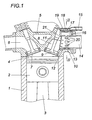
- the internal combustion engine according to the Fig. 1 has at least one cylinder 1 with a piston 2, which is connected via a connecting rod 3 in a conventional manner with a crankshaft.
- the combustion chamber 4 of the cylinder 1 is closed at the top by a cylinder head 5 which forms at least one inlet channel 6 with an inlet valve 7 and at least one outlet channel 8 with an outlet valve 9.
- the outlet channel 8 comprises a tubular insert 11 provided in a cylinder head opening 10, between which and the cylinder head opening 10 an annular gap 12 remains free.
- the insert 11 is in the form of a nozzle 13 formed as part of an exhaust line 14, which is connected in the usual way via an exhaust manifold to the outlet channel 8.
- the annular gap 12 is connected to an air line 15, through which the exhaust line 14 fresh air for afterburning combustible residues is supplied.
- the arrangement is made such that the annular gap 12 widens in the mouth region of the air line 15 to a chamber 16 which receives a diaphragm valve 17 for controlling the air line 15.
- the diaphragm valve 17 has a metallic membrane 18 as a valve body, for which a stop 19 is provided to limit the opening width.
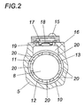
- the gas-dynamic effects in the exhaust gas line 14 are absorbed by the diaphragm valve without damping, which is thus controlled in direct dependence on these gas-dynamic effects and a self-priming supply the fresh air through passage openings 20 and an end-side edge gap 21 ensures to a sufficient extent.
- the formation of the tubular insert 11 as part of the exhaust line 14 also allows an advantageous heat conduction from the insert 11 to the continuing exhaust line, especially when the insert 11 is formed as a nozzle 13 of the exhaust line 14. This heat conduction from the insert 11 to the exhaust line 14 supports the heating of the exhaust line 14 during the warm-up phase of the internal combustion engine and brings a cooling of the insert 11, especially in the high load area with it.
Landscapes
- Engineering & Computer Science (AREA)
- Chemical & Material Sciences (AREA)
- Combustion & Propulsion (AREA)
- Mechanical Engineering (AREA)
- General Engineering & Computer Science (AREA)
- Chemical Kinetics & Catalysis (AREA)
- Health & Medical Sciences (AREA)
- Toxicology (AREA)
- Exhaust Gas After Treatment (AREA)
- Cylinder Crankcases Of Internal Combustion Engines (AREA)
- Exhaust Silencers (AREA)
Abstract
Description
- Die Erfindung bezieht sich auf eine Verbrennungskraftmaschine mit wenigstens einem Zylinder, dessen Zylinderkopf zumindest einen in einen Abgasstrang übergehenden Auslasskanal bildet, der einen rohrförmigen, unter Ausbildung eines Ringspaltes innerhalb einer Zylinderkopföffnung angeordneten Einsatz umfasst, wobei der mit dem Auslasskanal in Strömungsverbindung stehende Ringspalt an eine Luftleitung angeschlossen ist.
- Um die Schadstoffemission von Verbrennungskraftmaschinen zu verringern, ist es bekannt (
US 4 437 305 A ,US 4 727 717 A ,US 6 311 483 B ,US 3 927 525 A ), den Abgasen Frischluft für eine gegebenenfalls durch Katalysatoren unterstützte Nachverbrennung beispielsweise von Kohlenwasserstoffen oder Kohlenmonoxid in einem Abgasstrang über eine im Ansaugbereich durch ein Membranventil in Abhängigkeit von den Druckverhältnissen im Abgaskanal gesteuerte Luftleitung zuzuführen. Da die angestrebte Oxidation temperaturabhängig ist, lässt man die Luftleitung unmittelbar nach den Auslassventilen in den Auslassanal des Zylinderkopfes münden, sodass für eine rasche Erwärmung der Frischluft durch die heißen Abgase aus dem Brennraum des Zylinders und für eine unmittelbare Reaktion mit dem Abgas gesorgt ist. Durch die heißen Abgase kommt es bei Verbrennungskraftmaschinen insbesondere im Bereich der Auslasskanäle zu beachtlichen Wärmeeintragungen in den Zylinderkopf, was zu thermischen Verformungen und damit verbunden zu Dichtungsschwierigkeiten und einem erhöhten Verschleiß sowie einer erhöhten Klopfneigung bei der Verbrennung führen kann. Mit der Zufuhr sekundärer Frischluft in den Auslasskanal ist eine Kühlwirkung verbunden, die im Bereich der Abgase wegen der temperaturabhängigen Oxidationsvorgänge unerwünscht ist, im Bereich des Zylinderkopfes aber nicht ausreicht, um vor allem im Volllastbetrieb thermische Überlastungen auszuschließen. - Zur Vermeidung dieser Nachteile wurde bereits vorgeschlagen (
DE 103 27 305 A1 ), in der Zylinderkopföffnung für den Auslasskanal einen rohrförmigen Einsatz vorzusehen, zwischen dem und der Zylinderkopföffnung ein an die Luftleitung angeschlossener Ringspalt frei bleibt, über den die Frischluft durch Durchtrittsöffnungen im rohrförmigen Einsatz in den durch den Einsatz gebildeten Strömungskanal für die Abgase gelangt. Dieser mit Frischluft gespülte Ringspalt unterbindet einen unmittelbaren Wärmeübergang vom Auslasskanal in den Zylinderkopf und sorgt daher für eine Begrenzung der thermischen Belastung des Zylinderkopfes im Bereich des Auslasskanals. Es wird aber auch die Nachbehandlung der Abgase verbessert, weil die als Sekundärluft für die Nachverbrennung in den Ringspalt eingeführte Frischluft wegen der vergleichsweise großen Berührungsfläche einerseits mit dem Zylinderkopf und anderseits mit dem rohrförmigen Einsatz rasch erwärmt wird. Nachteilig ist allerdings, dass für die Frischluftförderung eine Pumpe vorzusehen ist. Außerdem ist der thermische Durchgriff vom rohrförmigen Einsatz auf den Abgasstrang unbefriedigend. - Der Erfindung liegt somit die Aufgabe zugrunde, eine Verbrennungskraftmaschine der eingangs geschilderten Art so auszugestalten, dass auf eine Förderpumpe für die Frischluft verzichtet werden kann, ohne Nachteile hinsichtlich der Frischluftführung in Kauf nehmen zu müssen. Darüber hinaus sollen vorteilhafte Wärmebedingungen im Abgasstrang sowohl beim Kaltstart als auch bei warmer Verbrennungskraftmaschine mit einfachen konstruktiven Mitteln erreicht werden.
- Die Erfindung löst die gestellte Aufgabe dadurch, dass der rohrförmige Einsatz Teil des Abgasstranges ist und dass sich der Ringspalt im Mündungsbereich der Luftleitung zu einer gegenüber der Luftleitung durch ein Membranventil abgegrenzten Kammer erweitert.
- Mit der Maßnahme, den rohrförmigen Einsatz als Teil des Abgasstranges auszubilden, wird nicht nur eine Konstruktionsvereinfachung erzielt, weil der rohrförmige Einsatz mit dem Anflanschen des Abgasstranges am Zylinderkopf innerhalb der Zylinderkopföffnung positioniert wird, sondern auch das thermische Verhalten des Abgasstranges verbessert. Während des Warmlaufens der Verbrennungskraftmaschine wird nämlich der Abgasstrang durch die Wärmeleitung über den rohrförmigen Einsatz schneller erwärmt, sodass Abgaskatalysatoren im Bereich des Abgasstranges in kürzerer Zeit die erforderliche Betriebstemperatur erreichen, was zu einem verringerten Emissionsausstoß führt. Bei warmer Verbrennungskraftmaschine wird hingegen insbesondere im Volllastbereich eine Kühlwirkung im Bereich des Auslasskanals erzielt, weil die vom rohrförmigen Einsatz aufgenommene Wärme unbehindert in den Abgasstrang weitergeleitet werden kann, wodurch die thermische Belastung des Zylinderkopfes mit dem zusätzlichen Vorteil gesenkt werden kann, dass die Klopfneigung insbesondere von luftgekühlten, hochbelasteten Ottomotoren deutlich verringert werden kann.
- Aufgrund des Anschlusses des Ringspaltes an die Luftleitung über eine den Ringspalt zwischen dem rohrförmigen Einsatz und der Zylinderkopföffnung für den Auslasskanal erweiternden Kammer, über die das die Luftleitung steuernde Membranventil mit dem Druck im Auslasskanal beaufschlagt wird, können die gasdynamischen Effekte weitgehend ungedämpft auf das Membranventil einwirken, sodass es keiner Förderpumpe bedarf, um die Frischluft in Abhängigkeit von den jeweils im Auslasskanal auftretenden Druckschwankungen über das Membranventil in den Abgasstrang anzusaugen. Zur Schonung des Membranventils kann diesem ein Anschlag für die Offenstellung des durch eine Membran gebildeten Ventilkörpers zugeordnet werden.
- Besonders einfache Konstruktionsverhältnisse ergeben sich im Zusammenhang mit dem erfindungsgemäßen Einsatz, wenn der rohrförmige Einsatz als ein in den Auslasskanal ragender Stutzen des Abgasstranges ausgebildet ist. In diesem Fall wird außerdem die Wärmeleitung vom in die Zylinderkopföffnung ragenden Einsatz in den Abgasstrang durch die Einstückigkeit des rohrförmigen Ansatzes mit dem weiterführenden Rohr des Abgasstranges vorteilhaft unterstützt.
- In der Zeichnung ist der Erfindungsgegenstand beispielsweise dargestellt. Es zeigen
- Fig. 1
- erfindungsgemäße Verbrennungskraftmaschine ausschnittsweise im Bereich eines Zylinderkopfes in einem schematischen Axialschnitt und die
- Fig. 2
- den Zylinderkopf in einem Schnitt gemäß der Linie II-II der
Fig. 1 in einem größeren Maßstab. - Die Verbrennungskraftmaschine gemäß der
Fig. 1 weist wenigstens einen Zylinder 1 mit einem Kolben 2 auf, der über eine Pleuelstange 3 in herkömmlicher Art mit einer Kurbelwelle verbunden ist. Der Brennraum 4 des Zylinders 1 ist nach oben durch einen Zylinderkopf 5 abgeschlossen, der wenigstens einen Einlasskanal 6 mit einem Einlassventil 7 sowie wenigstens einen Auslasskanal 8 mit einem Auslassventil 9 bildet. Der Auslasskanal 8 umfasst einen in einer Zylinderkopföffnung 10 vorgesehenen, rohrförmigen Einsatz 11, zwischen dem und der Zylinderkopföffnung 10 ein Ringspalt 12 frei bleibt. Der Einsatz 11 ist in Form eines Stutzens 13 als Teil eines Abgasstranges 14 ausgebildet, der in üblicher Weise über einen Auspuffkrümmer an den Auslasskanal 8 angeschlossen ist. - Der Ringspalt 12 ist mit einer Luftleitung 15 verbunden, durch die dem Abgasstrang 14 Frischluft zur Nachverbrennung brennbarer Reststoffe zugeführt wird. Die Anordnung ist dabei so getroffen, dass sich im Mündungsbereich der Luftleitung 15 der Ringspalt 12 zu einer Kammer 16 erweitert, die ein Membranventil 17 zur Steuerung der Luftleitung 15 aufnimmt. Das Membranventil 17 weist eine metallische Membran 18 als Ventilkörper auf, für den ein Anschlag 19 zur Begrenzung der Öffnungsweite vorgesehen ist.
- Aufgrund der Anordnung des Membranventils 17 in einer durch eine Erweiterung des Ringspaltes 12 erhaltenen Kammer 16 greifen die gasdynamischen Wirkungen im Abgasstrang 14 ohne eine ins gewicht fallende Dämpfung auf das Membranventil durch, das somit in unmittelbarer Abhängigkeit von diesen gasdynamischen Wirkungen angesteuert wird und eine selbstansaugende Zufuhr der Frischluft durch Durchtrittsöffnungen 20 bzw. einen stirnseitigen Randspalt 21 in einem ausreichenden Ausmaß sicherstellt. Die Ausbildung des rohrförmigen Einsatzes 11 als Teil des Abgasstranges 14 ermöglicht darüber hinaus eine vorteilhafte Wärmeleitung vom Einsatz 11 auf den weiterführenden Abgasstrang, insbesondere wenn der Einsatz 11 als Stutzen 13 des Abgasstranges 14 geformt ist. Diese Wärmeleitung vom Einsatz 11 zum Abgasstrang 14 unterstützt die Erwärmung des Abgasstranges 14 während der Warmlaufphase der Verbrennungskraftmaschine und bringt eine Kühlung des Einsatzes 11 vor allem im Hochlastbereich mit sich.
Claims (3)
- Verbrennungskraftmaschine mit wenigstens einem Zylinder, dessen Zy-linderkopf (5) zumindest einen in einen Abgasstrang (14) übergehenden Auslasskanal (8) bildet, der einen rohrförmigen, unter Ausbildung eines Ringspaltes (12) innerhalb einer Zylinderkopföffnung (10) angeordneten Einsatz (11) umfasst, wobei der mit dem Auslasskanat (8) in Strömungsverbindung stehende Ringspalt (12) an eine Luftleitung (15) angeschlossen ist, dadurch gekennzeichnet, dass der rohrförmige Einsatz (11) Teil des Abgasstranges (14) ist und dass sich der Ringspalt (12) im Mündungsbereich der Luftleitung (15) zu einer gegenüber der Luftleitung (15) durch ein Membranventil (17) abgegrenzten Kammer (16) erweitert.
- Verbrennungskraftmaschine nach Anspruch 1, dadurch gekennzeichnet, dass der Einsatz (11) als ein in den Auslasskanal (8) ragender Stutzen (13) des Abgasstranges (14) ausgebildet ist.
- Verbrennungskraftmaschine nach Anspruch 1 oder 2, dadurch gekennzeichnet, dass dem Membranventil (17) ein Anschlag (19) für die Offenstellung des durch eine Membran (18) gebildeten Ventilkörpers zugeordnet ist.
Applications Claiming Priority (2)
| Application Number | Priority Date | Filing Date | Title |
|---|---|---|---|
| AT0147907A AT505765B1 (de) | 2007-09-20 | 2007-09-20 | Verbrennungskraftmaschine |
| PCT/AT2008/000312 WO2009036476A1 (de) | 2007-09-20 | 2008-09-02 | Verbrennungskraftmaschine |
Publications (2)
| Publication Number | Publication Date |
|---|---|
| EP2191114A1 EP2191114A1 (de) | 2010-06-02 |
| EP2191114B1 true EP2191114B1 (de) | 2011-12-14 |
Family
ID=40090219
Family Applications (1)
| Application Number | Title | Priority Date | Filing Date |
|---|---|---|---|
| EP08782840A Not-in-force EP2191114B1 (de) | 2007-09-20 | 2008-09-02 | Verbrennungskraftmaschine |
Country Status (6)
| Country | Link |
|---|---|
| EP (1) | EP2191114B1 (de) |
| CN (1) | CN101835964B (de) |
| AT (2) | AT505765B1 (de) |
| ES (1) | ES2379031T3 (de) |
| TW (1) | TW200925396A (de) |
| WO (1) | WO2009036476A1 (de) |
Families Citing this family (1)
| Publication number | Priority date | Publication date | Assignee | Title |
|---|---|---|---|---|
| DE102016123375A1 (de) * | 2016-12-02 | 2018-06-07 | Volkswagen Aktiengesellschaft | Brennkraftmaschine mit einem Zylinderkopf sowie mit einem Sekundärluftsystem |
Family Cites Families (12)
| Publication number | Priority date | Publication date | Assignee | Title |
|---|---|---|---|---|
| US3635031A (en) * | 1970-09-09 | 1972-01-18 | Gen Motors Corp | Exhaust manifold reactor |
| US3927525A (en) * | 1973-05-25 | 1975-12-23 | Gen Motors Corp | Engine with exhaust manifold converter-reactor |
| JPS51133604A (en) * | 1975-05-15 | 1976-11-19 | Nissan Motor Co Ltd | Exhaust gas cleaner system of engine |
| JPS5793616A (en) | 1980-12-03 | 1982-06-10 | Honda Motor Co Ltd | Exhaust purifier for internal combustion engine |
| JPS58106119A (ja) | 1981-12-17 | 1983-06-24 | Honda Motor Co Ltd | 内燃機関における排気浄化装置 |
| US5761904A (en) * | 1994-03-28 | 1998-06-09 | Honda Giken Kogyo Kabushiki Kaisha | Air inlet structure for exhaust passage in engine |
| JP3659389B2 (ja) * | 1998-09-02 | 2005-06-15 | 本田技研工業株式会社 | 内燃機関の排気通路への二次空気導入構造 |
| JP4152499B2 (ja) * | 1998-09-14 | 2008-09-17 | 本田技研工業株式会社 | 排気2次エア通路の形成方法及び排気2次エア通路構造 |
| JP4093512B2 (ja) * | 1998-11-25 | 2008-06-04 | 本田技研工業株式会社 | エンジンの排気用二次空気供給装置 |
| DE10327305A1 (de) | 2003-06-18 | 2005-01-05 | Daimlerchrysler Ag | Brennkraftmaschine mit Sekundärluftbrause |
| JP2006057465A (ja) * | 2004-08-17 | 2006-03-02 | Yamaha Motor Co Ltd | エンジン |
| JP4704242B2 (ja) * | 2006-02-28 | 2011-06-15 | 本田技研工業株式会社 | 排気浄化用二次空気供給装置 |
-
2007
- 2007-09-20 AT AT0147907A patent/AT505765B1/de not_active IP Right Cessation
-
2008
- 2008-09-02 WO PCT/AT2008/000312 patent/WO2009036476A1/de not_active Ceased
- 2008-09-02 EP EP08782840A patent/EP2191114B1/de not_active Not-in-force
- 2008-09-02 ES ES08782840T patent/ES2379031T3/es active Active
- 2008-09-02 CN CN2008801128895A patent/CN101835964B/zh not_active Expired - Fee Related
- 2008-09-02 AT AT08782840T patent/ATE537339T1/de active
- 2008-09-17 TW TW097135551A patent/TW200925396A/zh unknown
Also Published As
| Publication number | Publication date |
|---|---|
| WO2009036476A1 (de) | 2009-03-26 |
| ATE537339T1 (de) | 2011-12-15 |
| CN101835964B (zh) | 2012-07-18 |
| EP2191114A1 (de) | 2010-06-02 |
| AT505765B1 (de) | 2009-04-15 |
| AT505765A4 (de) | 2009-04-15 |
| CN101835964A (zh) | 2010-09-15 |
| ES2379031T3 (es) | 2012-04-20 |
| TW200925396A (en) | 2009-06-16 |
Similar Documents
| Publication | Publication Date | Title |
|---|---|---|
| DE102005002518B3 (de) | Abgasrückführungssystem für eine Brennkraftmaschine sowie Abgasrückführungsverfahren | |
| DE112014000854T5 (de) | Niederdruck-Abgasrezirkulationsmodul | |
| DE102012022416B4 (de) | Ladeluftkühleranordnung | |
| EP2191114B1 (de) | Verbrennungskraftmaschine | |
| DE102010051562B4 (de) | Abgasführungsvorrichtung für eine Verbrennungskraftmaschine | |
| DE102021002863A1 (de) | Verbrennungskraftmaschine für ein Kraftfahrzeug, insbesondere für einen Kraftwagen | |
| EP2574795B1 (de) | Abgasturbolader für eine Verbrennungskraftmaschine | |
| DE102010048793B3 (de) | Abgasführungsvorrichtung für eine Verbrennungskraftmaschine | |
| DE4301835C1 (de) | Motorbremse fuer eine dieselbrennkraftmaschine | |
| DE10240265B4 (de) | Kombiventil | |
| DE102020100967B4 (de) | Kombiniertes Rückschlag- und Absperrventil für eine Verbrennungskraftmaschine | |
| DE102021001881A1 (de) | Verbrennungskraftmaschine für ein Kraftfahrzeug, insbesondere für einen Kraftwagen | |
| DE102008014437A1 (de) | Abgasstrang | |
| DE102005062186B4 (de) | Vorrichtung zur Abgaskühlung | |
| EP3548721B1 (de) | Brennkraftmaschine mit einem zylinderkopf sowie mit einem sekundärluftsystem | |
| DE102007045634A1 (de) | Zylinderkopf für einen Verbrennungsmotor | |
| WO2013079427A1 (de) | Brennkraftmaschine mit einer anordnung zur rückführung von abgas und zuführung von gekühlter ladeluft | |
| DE1751799A1 (de) | Abgasnachverbrennungseinrichtung fuer innere Verbrennungskraftmaschinen | |
| DE102016006146B3 (de) | Antriebseinrichtung sowie Verfahren zum Betreiben einer Antriebseinrichtung | |
| WO2020057813A1 (de) | Abgasstrang zur abgasnachbehandlung | |
| DE102004049589A1 (de) | Wasserstoffmotor mit optimierter Kraftstoffeinblasvorrichtung | |
| DE3536804C2 (de) | ||
| DE102021005317A1 (de) | Verbrennungskraftmaschine für ein Kraftfahrzeug, insbesondere für einen Kraftwagen | |
| DE102017219167A1 (de) | Brennkraftmaschine mit einem Abgasstrang und mit einem Sekundärluftsystem | |
| EP1762707B1 (de) | Gasmotor |
Legal Events
| Date | Code | Title | Description |
|---|---|---|---|
| PUAI | Public reference made under article 153(3) epc to a published international application that has entered the european phase |
Free format text: ORIGINAL CODE: 0009012 |
|
| 17P | Request for examination filed |
Effective date: 20100401 |
|
| AK | Designated contracting states |
Kind code of ref document: A1 Designated state(s): AT BE BG CH CY CZ DE DK EE ES FI FR GB GR HR HU IE IS IT LI LT LU LV MC MT NL NO PL PT RO SE SI SK TR |
|
| AX | Request for extension of the european patent |
Extension state: AL BA MK RS |
|
| DAX | Request for extension of the european patent (deleted) | ||
| GRAP | Despatch of communication of intention to grant a patent |
Free format text: ORIGINAL CODE: EPIDOSNIGR1 |
|
| RIC1 | Information provided on ipc code assigned before grant |
Ipc: F01N 3/34 20060101AFI20110413BHEP Ipc: F02F 1/42 20060101ALI20110413BHEP Ipc: F01N 13/10 20100101ALI20110413BHEP |
|
| GRAS | Grant fee paid |
Free format text: ORIGINAL CODE: EPIDOSNIGR3 |
|
| GRAA | (expected) grant |
Free format text: ORIGINAL CODE: 0009210 |
|
| AK | Designated contracting states |
Kind code of ref document: B1 Designated state(s): AT BE BG CH CY CZ DE DK EE ES FI FR GB GR HR HU IE IS IT LI LT LU LV MC MT NL NO PL PT RO SE SI SK TR |
|
| REG | Reference to a national code |
Ref country code: GB Ref legal event code: FG4D Free format text: NOT ENGLISH |
|
| REG | Reference to a national code |
Ref country code: CH Ref legal event code: EP |
|
| REG | Reference to a national code |
Ref country code: IE Ref legal event code: FG4D |
|
| REG | Reference to a national code |
Ref country code: DE Ref legal event code: R096 Ref document number: 502008005860 Country of ref document: DE Effective date: 20120216 |
|
| REG | Reference to a national code |
Ref country code: NL Ref legal event code: T3 |
|
| REG | Reference to a national code |
Ref country code: ES Ref legal event code: FG2A Ref document number: 2379031 Country of ref document: ES Kind code of ref document: T3 Effective date: 20120420 |
|
| PG25 | Lapsed in a contracting state [announced via postgrant information from national office to epo] |
Ref country code: NO Free format text: LAPSE BECAUSE OF FAILURE TO SUBMIT A TRANSLATION OF THE DESCRIPTION OR TO PAY THE FEE WITHIN THE PRESCRIBED TIME-LIMIT Effective date: 20120314 Ref country code: LT Free format text: LAPSE BECAUSE OF FAILURE TO SUBMIT A TRANSLATION OF THE DESCRIPTION OR TO PAY THE FEE WITHIN THE PRESCRIBED TIME-LIMIT Effective date: 20111214 |
|
| RAP2 | Party data changed (patent owner data changed or rights of a patent transferred) |
Owner name: HANS LEEB GMBH |
|
| REG | Reference to a national code |
Ref country code: NL Ref legal event code: SD Effective date: 20120423 |
|
| RIN2 | Information on inventor provided after grant (corrected) |
Inventor name: KIRCHBERGER, ROLAND |
|
| LTIE | Lt: invalidation of european patent or patent extension |
Effective date: 20111214 |
|
| PG25 | Lapsed in a contracting state [announced via postgrant information from national office to epo] |
Ref country code: HR Free format text: LAPSE BECAUSE OF FAILURE TO SUBMIT A TRANSLATION OF THE DESCRIPTION OR TO PAY THE FEE WITHIN THE PRESCRIBED TIME-LIMIT Effective date: 20111214 Ref country code: LV Free format text: LAPSE BECAUSE OF FAILURE TO SUBMIT A TRANSLATION OF THE DESCRIPTION OR TO PAY THE FEE WITHIN THE PRESCRIBED TIME-LIMIT Effective date: 20111214 Ref country code: SE Free format text: LAPSE BECAUSE OF FAILURE TO SUBMIT A TRANSLATION OF THE DESCRIPTION OR TO PAY THE FEE WITHIN THE PRESCRIBED TIME-LIMIT Effective date: 20111214 Ref country code: SI Free format text: LAPSE BECAUSE OF FAILURE TO SUBMIT A TRANSLATION OF THE DESCRIPTION OR TO PAY THE FEE WITHIN THE PRESCRIBED TIME-LIMIT Effective date: 20111214 Ref country code: GR Free format text: LAPSE BECAUSE OF FAILURE TO SUBMIT A TRANSLATION OF THE DESCRIPTION OR TO PAY THE FEE WITHIN THE PRESCRIBED TIME-LIMIT Effective date: 20120315 |
|
| PG25 | Lapsed in a contracting state [announced via postgrant information from national office to epo] |
Ref country code: CY Free format text: LAPSE BECAUSE OF FAILURE TO SUBMIT A TRANSLATION OF THE DESCRIPTION OR TO PAY THE FEE WITHIN THE PRESCRIBED TIME-LIMIT Effective date: 20111214 |
|
| REG | Reference to a national code |
Ref country code: IE Ref legal event code: FD4D |
|
| PG25 | Lapsed in a contracting state [announced via postgrant information from national office to epo] |
Ref country code: CZ Free format text: LAPSE BECAUSE OF FAILURE TO SUBMIT A TRANSLATION OF THE DESCRIPTION OR TO PAY THE FEE WITHIN THE PRESCRIBED TIME-LIMIT Effective date: 20111214 Ref country code: IE Free format text: LAPSE BECAUSE OF FAILURE TO SUBMIT A TRANSLATION OF THE DESCRIPTION OR TO PAY THE FEE WITHIN THE PRESCRIBED TIME-LIMIT Effective date: 20111214 Ref country code: SK Free format text: LAPSE BECAUSE OF FAILURE TO SUBMIT A TRANSLATION OF THE DESCRIPTION OR TO PAY THE FEE WITHIN THE PRESCRIBED TIME-LIMIT Effective date: 20111214 Ref country code: EE Free format text: LAPSE BECAUSE OF FAILURE TO SUBMIT A TRANSLATION OF THE DESCRIPTION OR TO PAY THE FEE WITHIN THE PRESCRIBED TIME-LIMIT Effective date: 20111214 Ref country code: IS Free format text: LAPSE BECAUSE OF FAILURE TO SUBMIT A TRANSLATION OF THE DESCRIPTION OR TO PAY THE FEE WITHIN THE PRESCRIBED TIME-LIMIT Effective date: 20120414 Ref country code: BG Free format text: LAPSE BECAUSE OF FAILURE TO SUBMIT A TRANSLATION OF THE DESCRIPTION OR TO PAY THE FEE WITHIN THE PRESCRIBED TIME-LIMIT Effective date: 20120314 |
|
| PG25 | Lapsed in a contracting state [announced via postgrant information from national office to epo] |
Ref country code: PT Free format text: LAPSE BECAUSE OF FAILURE TO SUBMIT A TRANSLATION OF THE DESCRIPTION OR TO PAY THE FEE WITHIN THE PRESCRIBED TIME-LIMIT Effective date: 20120416 Ref country code: PL Free format text: LAPSE BECAUSE OF FAILURE TO SUBMIT A TRANSLATION OF THE DESCRIPTION OR TO PAY THE FEE WITHIN THE PRESCRIBED TIME-LIMIT Effective date: 20111214 Ref country code: RO Free format text: LAPSE BECAUSE OF FAILURE TO SUBMIT A TRANSLATION OF THE DESCRIPTION OR TO PAY THE FEE WITHIN THE PRESCRIBED TIME-LIMIT Effective date: 20111214 |
|
| REG | Reference to a national code |
Ref country code: AT Ref legal event code: PC Ref document number: 537339 Country of ref document: AT Kind code of ref document: T Owner name: HANS LEEB GMBH, AT Effective date: 20120904 |
|
| PLBE | No opposition filed within time limit |
Free format text: ORIGINAL CODE: 0009261 |
|
| STAA | Information on the status of an ep patent application or granted ep patent |
Free format text: STATUS: NO OPPOSITION FILED WITHIN TIME LIMIT |
|
| PG25 | Lapsed in a contracting state [announced via postgrant information from national office to epo] |
Ref country code: DK Free format text: LAPSE BECAUSE OF FAILURE TO SUBMIT A TRANSLATION OF THE DESCRIPTION OR TO PAY THE FEE WITHIN THE PRESCRIBED TIME-LIMIT Effective date: 20111214 |
|
| 26N | No opposition filed |
Effective date: 20120917 |
|
| PGFP | Annual fee paid to national office [announced via postgrant information from national office to epo] |
Ref country code: ES Payment date: 20120803 Year of fee payment: 5 Ref country code: FR Payment date: 20120927 Year of fee payment: 5 |
|
| REG | Reference to a national code |
Ref country code: DE Ref legal event code: R097 Ref document number: 502008005860 Country of ref document: DE Effective date: 20120917 |
|
| PGFP | Annual fee paid to national office [announced via postgrant information from national office to epo] |
Ref country code: BE Payment date: 20120927 Year of fee payment: 5 |
|
| PGFP | Annual fee paid to national office [announced via postgrant information from national office to epo] |
Ref country code: IT Payment date: 20120927 Year of fee payment: 5 |
|
| PGFP | Annual fee paid to national office [announced via postgrant information from national office to epo] |
Ref country code: NL Payment date: 20120924 Year of fee payment: 5 |
|
| PG25 | Lapsed in a contracting state [announced via postgrant information from national office to epo] |
Ref country code: MC Free format text: LAPSE BECAUSE OF NON-PAYMENT OF DUE FEES Effective date: 20120930 |
|
| REG | Reference to a national code |
Ref country code: CH Ref legal event code: PL |
|
| GBPC | Gb: european patent ceased through non-payment of renewal fee |
Effective date: 20120902 |
|
| PG25 | Lapsed in a contracting state [announced via postgrant information from national office to epo] |
Ref country code: FI Free format text: LAPSE BECAUSE OF FAILURE TO SUBMIT A TRANSLATION OF THE DESCRIPTION OR TO PAY THE FEE WITHIN THE PRESCRIBED TIME-LIMIT Effective date: 20111214 |
|
| PG25 | Lapsed in a contracting state [announced via postgrant information from national office to epo] |
Ref country code: LI Free format text: LAPSE BECAUSE OF NON-PAYMENT OF DUE FEES Effective date: 20120930 Ref country code: CH Free format text: LAPSE BECAUSE OF NON-PAYMENT OF DUE FEES Effective date: 20120930 Ref country code: GB Free format text: LAPSE BECAUSE OF NON-PAYMENT OF DUE FEES Effective date: 20120902 |
|
| PG25 | Lapsed in a contracting state [announced via postgrant information from national office to epo] |
Ref country code: MT Free format text: LAPSE BECAUSE OF FAILURE TO SUBMIT A TRANSLATION OF THE DESCRIPTION OR TO PAY THE FEE WITHIN THE PRESCRIBED TIME-LIMIT Effective date: 20111214 |
|
| BERE | Be: lapsed |
Owner name: HANS LEEB G.M.B.H. Effective date: 20130930 |
|
| REG | Reference to a national code |
Ref country code: NL Ref legal event code: V1 Effective date: 20140401 |
|
| PG25 | Lapsed in a contracting state [announced via postgrant information from national office to epo] |
Ref country code: TR Free format text: LAPSE BECAUSE OF FAILURE TO SUBMIT A TRANSLATION OF THE DESCRIPTION OR TO PAY THE FEE WITHIN THE PRESCRIBED TIME-LIMIT Effective date: 20111214 |
|
| PG25 | Lapsed in a contracting state [announced via postgrant information from national office to epo] |
Ref country code: LU Free format text: LAPSE BECAUSE OF NON-PAYMENT OF DUE FEES Effective date: 20120902 |
|
| REG | Reference to a national code |
Ref country code: FR Ref legal event code: ST Effective date: 20140530 |
|
| PG25 | Lapsed in a contracting state [announced via postgrant information from national office to epo] |
Ref country code: HU Free format text: LAPSE BECAUSE OF FAILURE TO SUBMIT A TRANSLATION OF THE DESCRIPTION OR TO PAY THE FEE WITHIN THE PRESCRIBED TIME-LIMIT Effective date: 20080902 Ref country code: BE Free format text: LAPSE BECAUSE OF NON-PAYMENT OF DUE FEES Effective date: 20130930 |
|
| PG25 | Lapsed in a contracting state [announced via postgrant information from national office to epo] |
Ref country code: IT Free format text: LAPSE BECAUSE OF NON-PAYMENT OF DUE FEES Effective date: 20130902 Ref country code: FR Free format text: LAPSE BECAUSE OF NON-PAYMENT OF DUE FEES Effective date: 20130930 Ref country code: NL Free format text: LAPSE BECAUSE OF NON-PAYMENT OF DUE FEES Effective date: 20140401 |
|
| REG | Reference to a national code |
Ref country code: ES Ref legal event code: FD2A Effective date: 20141010 |
|
| PGFP | Annual fee paid to national office [announced via postgrant information from national office to epo] |
Ref country code: DE Payment date: 20140819 Year of fee payment: 7 |
|
| PGFP | Annual fee paid to national office [announced via postgrant information from national office to epo] |
Ref country code: AT Payment date: 20140925 Year of fee payment: 7 |
|
| PG25 | Lapsed in a contracting state [announced via postgrant information from national office to epo] |
Ref country code: ES Free format text: LAPSE BECAUSE OF NON-PAYMENT OF DUE FEES Effective date: 20130903 |
|
| REG | Reference to a national code |
Ref country code: DE Ref legal event code: R119 Ref document number: 502008005860 Country of ref document: DE |
|
| REG | Reference to a national code |
Ref country code: AT Ref legal event code: MM01 Ref document number: 537339 Country of ref document: AT Kind code of ref document: T Effective date: 20150902 |
|
| PG25 | Lapsed in a contracting state [announced via postgrant information from national office to epo] |
Ref country code: DE Free format text: LAPSE BECAUSE OF NON-PAYMENT OF DUE FEES Effective date: 20160401 |
|
| PG25 | Lapsed in a contracting state [announced via postgrant information from national office to epo] |
Ref country code: AT Free format text: LAPSE BECAUSE OF NON-PAYMENT OF DUE FEES Effective date: 20150902 |