EP2191126B1 - Dispositif et procédé de recirculation des gaz d'échappement d'un moteur thermique - Google Patents
Dispositif et procédé de recirculation des gaz d'échappement d'un moteur thermique Download PDFInfo
- Publication number
- EP2191126B1 EP2191126B1 EP08857465A EP08857465A EP2191126B1 EP 2191126 B1 EP2191126 B1 EP 2191126B1 EP 08857465 A EP08857465 A EP 08857465A EP 08857465 A EP08857465 A EP 08857465A EP 2191126 B1 EP2191126 B1 EP 2191126B1
- Authority
- EP
- European Patent Office
- Prior art keywords
- pipe
- duct
- exhaust
- heat
- valve
- Prior art date
- Legal status (The legal status is an assumption and is not a legal conclusion. Google has not performed a legal analysis and makes no representation as to the accuracy of the status listed.)
- Not-in-force
Links
Images


Classifications
-
- F—MECHANICAL ENGINEERING; LIGHTING; HEATING; WEAPONS; BLASTING
- F01—MACHINES OR ENGINES IN GENERAL; ENGINE PLANTS IN GENERAL; STEAM ENGINES
- F01N—GAS-FLOW SILENCERS OR EXHAUST APPARATUS FOR MACHINES OR ENGINES IN GENERAL; GAS-FLOW SILENCERS OR EXHAUST APPARATUS FOR INTERNAL-COMBUSTION ENGINES
- F01N5/00—Exhaust or silencing apparatus combined or associated with devices profiting by exhaust energy
- F01N5/02—Exhaust or silencing apparatus combined or associated with devices profiting by exhaust energy the devices using heat
-
- F—MECHANICAL ENGINEERING; LIGHTING; HEATING; WEAPONS; BLASTING
- F02—COMBUSTION ENGINES; HOT-GAS OR COMBUSTION-PRODUCT ENGINE PLANTS
- F02M—SUPPLYING COMBUSTION ENGINES IN GENERAL WITH COMBUSTIBLE MIXTURES OR CONSTITUENTS THEREOF
- F02M26/00—Engine-pertinent apparatus for adding exhaust gases to combustion-air, main fuel or fuel-air mixture, e.g. by exhaust gas recirculation [EGR] systems
- F02M26/02—EGR systems specially adapted for supercharged engines
- F02M26/04—EGR systems specially adapted for supercharged engines with a single turbocharger
- F02M26/06—Low pressure loops, i.e. wherein recirculated exhaust gas is taken out from the exhaust downstream of the turbocharger turbine and reintroduced into the intake system upstream of the compressor
-
- F—MECHANICAL ENGINEERING; LIGHTING; HEATING; WEAPONS; BLASTING
- F02—COMBUSTION ENGINES; HOT-GAS OR COMBUSTION-PRODUCT ENGINE PLANTS
- F02M—SUPPLYING COMBUSTION ENGINES IN GENERAL WITH COMBUSTIBLE MIXTURES OR CONSTITUENTS THEREOF
- F02M26/00—Engine-pertinent apparatus for adding exhaust gases to combustion-air, main fuel or fuel-air mixture, e.g. by exhaust gas recirculation [EGR] systems
- F02M26/13—Arrangement or layout of EGR passages, e.g. in relation to specific engine parts or for incorporation of accessories
- F02M26/14—Arrangement or layout of EGR passages, e.g. in relation to specific engine parts or for incorporation of accessories in relation to the exhaust system
- F02M26/15—Arrangement or layout of EGR passages, e.g. in relation to specific engine parts or for incorporation of accessories in relation to the exhaust system in relation to engine exhaust purifying apparatus
-
- F—MECHANICAL ENGINEERING; LIGHTING; HEATING; WEAPONS; BLASTING
- F02—COMBUSTION ENGINES; HOT-GAS OR COMBUSTION-PRODUCT ENGINE PLANTS
- F02M—SUPPLYING COMBUSTION ENGINES IN GENERAL WITH COMBUSTIBLE MIXTURES OR CONSTITUENTS THEREOF
- F02M26/00—Engine-pertinent apparatus for adding exhaust gases to combustion-air, main fuel or fuel-air mixture, e.g. by exhaust gas recirculation [EGR] systems
- F02M26/13—Arrangement or layout of EGR passages, e.g. in relation to specific engine parts or for incorporation of accessories
- F02M26/22—Arrangement or layout of EGR passages, e.g. in relation to specific engine parts or for incorporation of accessories with coolers in the recirculation passage
- F02M26/23—Layout, e.g. schematics
- F02M26/25—Layout, e.g. schematics with coolers having bypasses
-
- F—MECHANICAL ENGINEERING; LIGHTING; HEATING; WEAPONS; BLASTING
- F02—COMBUSTION ENGINES; HOT-GAS OR COMBUSTION-PRODUCT ENGINE PLANTS
- F02M—SUPPLYING COMBUSTION ENGINES IN GENERAL WITH COMBUSTIBLE MIXTURES OR CONSTITUENTS THEREOF
- F02M26/00—Engine-pertinent apparatus for adding exhaust gases to combustion-air, main fuel or fuel-air mixture, e.g. by exhaust gas recirculation [EGR] systems
- F02M26/13—Arrangement or layout of EGR passages, e.g. in relation to specific engine parts or for incorporation of accessories
- F02M26/22—Arrangement or layout of EGR passages, e.g. in relation to specific engine parts or for incorporation of accessories with coolers in the recirculation passage
- F02M26/23—Layout, e.g. schematics
- F02M26/28—Layout, e.g. schematics with liquid-cooled heat exchangers
-
- F—MECHANICAL ENGINEERING; LIGHTING; HEATING; WEAPONS; BLASTING
- F02—COMBUSTION ENGINES; HOT-GAS OR COMBUSTION-PRODUCT ENGINE PLANTS
- F02M—SUPPLYING COMBUSTION ENGINES IN GENERAL WITH COMBUSTIBLE MIXTURES OR CONSTITUENTS THEREOF
- F02M26/00—Engine-pertinent apparatus for adding exhaust gases to combustion-air, main fuel or fuel-air mixture, e.g. by exhaust gas recirculation [EGR] systems
- F02M2026/001—Arrangements; Control features; Details
- F02M2026/004—EGR valve controlled by a temperature signal or an air/fuel ratio (lambda) signal
-
- Y—GENERAL TAGGING OF NEW TECHNOLOGICAL DEVELOPMENTS; GENERAL TAGGING OF CROSS-SECTIONAL TECHNOLOGIES SPANNING OVER SEVERAL SECTIONS OF THE IPC; TECHNICAL SUBJECTS COVERED BY FORMER USPC CROSS-REFERENCE ART COLLECTIONS [XRACs] AND DIGESTS
- Y02—TECHNOLOGIES OR APPLICATIONS FOR MITIGATION OR ADAPTATION AGAINST CLIMATE CHANGE
- Y02T—CLIMATE CHANGE MITIGATION TECHNOLOGIES RELATED TO TRANSPORTATION
- Y02T10/00—Road transport of goods or passengers
- Y02T10/10—Internal combustion engine [ICE] based vehicles
- Y02T10/12—Improving ICE efficiencies
Definitions
- the invention relates to the automotive field and relates to the management of exhaust gases from heat engines. It relates more particularly to the recirculation of exhaust gases.
- a recycling duct connects the exhaust duct to the intake duct via a valve for regulating the amount of gas recirculated and via a heat exchanger for cooling these same gases.
- the document FR 2,885,178 discloses a device for cleaning the exhaust gas recirculation circuit.
- the object of the invention is to improve these EGR devices by filling the heat exchanger with an additional function.
- Such a recycling device makes it possible, in addition to ensuring its primary function of recycling the exhaust gases, to put the heat exchanger into service even if no exhaust gas is admitted to be recycled in the intake. .
- the exhaust gases can thus be allowed to circulate continuously in the heat exchanger without being reinjected into the intake.
- the exchanger it is possible to use the exchanger as a source of heat even when the recycling device is not activated.
- the heat exchanger thus has a dual function: to cool the recycled gases when necessary and to provide a source of heat available at all times.
- the diversion branch is connected to a conduit deflection device so that the recirculation device has two possible output paths downstream of the heat exchanger: the recycling duct and the deflection duct.
- the device comprises a first closure valve for the deflection duct and / or a second closure valve in the recycling duct, thus making it possible to select and regulate the flows flowing in the deflection duct and in the duct. Recycling duct downstream of the exchanger.
- a three-way valve can be advantageously provided for grouping said first and second valves as well as the deflection branch.
- the heat exchanger may comprise inlet / outlet pipes adapted to circulate a heat transfer fluid between the heat exchanger and a heat generating device, so as to use this heat generating device as a source of heat adaptable to any place of the vehicle and powered by the heat of the exhaust gas.
- the deflection duct is connected to the exhaust duct.
- the exhaust gases thus complete their path in the exhaust duct, whether or not they have been allowed to circulate in the deflection duct, which avoids providing for the deflection duct a specific outlet, distinct from the duct. exhaust.
- This heat engine may further comprise an oxidation catalyst, the recycling duct being connected to the exhaust duct downstream of the oxidation catalyst, which makes it possible to benefit from the reduction of hydrocarbons provided by the oxidation catalyst for the gases passing through the exchanger, in order to avoid the phenomena of sticking and fouling of the exchanger and any valves arranged downstream.
- an oxidation catalyst the recycling duct being connected to the exhaust duct downstream of the oxidation catalyst, which makes it possible to benefit from the reduction of hydrocarbons provided by the oxidation catalyst for the gases passing through the exchanger, in order to avoid the phenomena of sticking and fouling of the exchanger and any valves arranged downstream.
- This engine may also include at least one element selected from a reduction catalyst, a nitrogen oxide trap and a particulate filter, the recycle line being connected to the exhaust duct upstream of said element, which avoids introducing an additional pressure drop. in the exhaust duct.
- the deflection duct may further be connected to the exhaust duct downstream of said element.
- the recycling duct may be connected at one of its ends to the exhaust duct downstream of the turbine of the turbocharger and may also be connected by the other of its ends at the intake duct upstream of the turbocharger compressor.
- the recirculation device thus operates at low pressure.
- Such a method can implement conventional sensors connected to an engine control unit ("ECU").
- ECU engine control unit
- the ECU controls said valve between a fully closed position (if a substantial flow of exhaust gas is already in recirculation to the inlet) and a fully open position (if no exhaust gas is allowed to recirculate).
- Such a module can advantageously be produced in the form of an integrable autonomous subset as a component in a motor architecture.
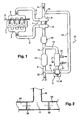
- the figure 1 represents a simplified engine architecture showing an engine equipped with an "EGR" recirculation device.
- the engine block 1 is schematically shown in plan view. It is served by an intake manifold 2 connected to an intake duct 3 and by an exhaust manifold 4 connected to an exhaust duct 5.
- the engine is supercharged and the intake duct 3 passes through the compressor 6 of a turbocharger 7 while the exhaust pipe 5 passes through the turbine 8 of the same turbocharger 7.
- the intake duct 3 is intended to be connected by its free end to an air filter (not shown) while a conventional injection-type device 9 is provided.
- the exhaust duct 5 comprises, in the present example, a catalytic exhaust pipe comprising an oxidation catalyst 10 and, downstream of the latter, a reduction catalyst 11.
- the oxidation catalyst can moreover, be replaced by a fast-start catalyst and the reduction catalyst by a three-way catalyst.
- the oxidation catalyst 10 of the present example will advantageously be of metal rather than ceramic structure so as to reduce the risk of damage to the compressor 6 by particles.
- the recirculation device 12 comprises a recycling duct 13 which is connected at one of its ends, at a first branch 14, to the exhaust duct 5, this first branch 14 being situated between the oxidation catalysts. 10 and reduction 11; and which is connected by the other of its ends, at a second branch 15, to the intake duct 3.
- This recycling duct 13 comprises in its path a heat exchanger 16 and a third branch 17, called a "deflection branch" at which a three-way valve 18 is disposed.
- the third branch 17 connects the recycling duct 13 to a deflection duct 19 which, in the present example, is connected to the exhaust duct 5 at a fourth branch 20, the latter being situated downstream of the reduction catalyst 11.
- the term "three-way valve” means a valve having an input channel and two output channels and adapted to direct the input stream to one or the other or both of the output channels in an adjustable manner.
- the figure 2 schematically represents the constituent elements of the valve 18.
- the three-way valve 18 of this example integrates the third branch 17 to the extent that it internally comprises an inlet channel 22 from the heat exchanger 16 via the recirculation duct 13 and a branch 17 leading to two output channels 23, 24 respectively to the recycling duct 13 and to the deflection duct 19.
- a valve here formed by a butterfly 25, 26 which can be be adapted to take any position between the opening and closing of the corresponding conduit, or operate "all or nothing" (open or closed).
- These butterflies 25, 26 are controlled in a conventional manner by an electric motor (not shown) itself controlled by an electronic control module (not shown), generally called “ECU”("Electronic Control Unit") which also drives the throttles, injectors and various other actuators.
- the heat exchanger 16 is further connected to inlet / outlet pipes 21 adapted to circulate a coolant in the exchanger 16.
- the exhaust gas passing through the exchanger 16 is thus cooled as said fluid coolant warms up.
- the pipes 21 are advantageously connected to any conventional device producing heat from a hot fluid (for example a cabin radiator or a device for accelerating the engine warming during a cold start).
- the above-mentioned ECU can, via conventional sensors, detect the need for heat generation.
- the recirculation device which has just been described operates as indicated below.
- the flue gases are evacuated from the engine 1 by the exhaust manifold 4 under high pressure and run through the exhaust pipe 5 to turbocharger 7 where their energy is used to rotate the turbine 8. These gases burned out of the turbocharger 7 continue their journey under low pressure along the exhaust pipe 5 to cross the oxidation catalyst 10 and the reducing catalyst 11 to then be evacuated by the silencer of the muffler (not shown) of the vehicle.
- the ECU controls the position of the throttles 25, 26 as a function of the heat input requirement of the heating device to which the exchanger 16 is connected.
- the three-way valve 18 can be replaced by two conventional valves corresponding to the two butterflies 25, 26, disposed one on the deflection duct 19 and the other on the recycling duct 13.
- the deflection duct 19 can lead elsewhere than in the exhaust duct 5, it can for example lead into a dedicated exhaust duct, separate from the muffler.
- the position of the first branch 14 it can be placed elsewhere on the exhaust duct 5, either upstream or downstream of the catalysts.
- the reduction catalyst 11 may be supplemented or replaced by a nitrogen oxide trap or a particulate filter.
- the present embodiment refers to a recirculation device operating at low pressure with respect to the turbocharger 7, it is also conceivable to adapt it to high pressure operation, the recycling duct 13 then being connected to the intake duct 3 downstream of the compressor 6 and to the exhaust duct 5 upstream of the turbine 8.
- the recirculation device can be adapted to a motor architecture without turbocharger.
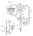
- the figure 3 shows a second embodiment of the invention.
- the elements having the same function as those of the first embodiment have the same reference numbers followed by a premium (').
- the first branch 14 ' is situated between a catalyst 27, for example a DOC ("Diesel Oxydation Catalyst") and a particulate filter 28 both disposed on the exhaust duct 5'.
- the recycling duct 13 ' which starts from this first branch 14', comprises a conventional valve 29 before the branch 15 'connecting it to the intake duct 3'.
- the deflection duct 19 ' starts from the deflection branch 17' to reach the fourth branch 20 'which is situated between the catalyst 27 and the particulate filter 28, upstream of the first branch 14'.
- a valve 30 carries this branch 20 'and a butterfly device adapted to close and open the deflection duct 19' and / or the exhaust duct 5 '.
- the valve 30, shown at figure 4 can also be a three-way valve whose inlet 40 is connected to the catalyst 27, an outlet 41 is connected to the branch 14 'and an outlet 42 is connected to the deflection duct 19'. Butterflies 43, 44 are respectively disposed in the outlets 42 and 41.
- this valve 30 closes the exhaust duct 5 'and opens the deflection duct 19', all the exhaust gases are allowed to circulate in the exchanger 16 ', thus allowing the exchanger to fulfill its function of heat input. In this configuration, a portion of these exhaust gases can still be allowed to recirculate in the intake through the opening of the valve 29.
- the valve 30 is adapted to close the exhaust duct 5 'with the butterfly 44 disposed between the branch 20' and the branch 14 '.
- a valve 32 according to the figure 6 is disposed on the branch 20 ', with its inlet 33 connected to the branch 14', an outlet 34 connected to the particulate filter 28 and an outlet 35 connected to the deflection duct 19 '.
- Butterflies 36, 37 are provided respectively in the inlet 33 and the outlet 35.
- a valve 31 is further disposed at the branch 15 '.
- This valve 31 is identical to the valve 32 and can therefore be described with reference to the figure 6 by using the same reference numbers.
- the inlet 33 of the valve 32 is connected to the intake duct 3 ', an outlet 34 is connected to the compressor 6' and an outlet 35 is connected to the recycling duct 13 '.
- the valve 31 fulfills an intake air metering function by virtue of the throttle valve 36, as is conventionally the throttle housing of a gasoline engine or the metering device of a diesel engine, while the throttle valve 37 also allows it to perform the EGR function.
- the valve 32 for its part, fulfills the function of exhaust back-pressure flap by means of its throttle valve 36, while the throttle valve 37 makes it possible or not for the return of the gases coming from the exchanger 16 'towards the exhaust duct. 'exhaust 5'.
- the butterfly valve 36 of the valve 32 is at least partially closed, so that intake gases pass through the exchanger 16, while the butterfly 37 of the valve 31 regulates in a conventional manner the rate of exhaust gas to be reinjected into the intake.
- the excess exhaust gas can be redirected to the exhaust duct 5 'by the control of the throttle 37 of the valve 32.
- the throttle valve 36 of the valve 31 is during this time controlled in a conventional manner as throttle body or dosing device. 'air.
- the butterflies 36 and 37 of the valve 32 are at least partially respectively closed and open while the butterfly 37 the valve 31 remains closed.
- the figure 7 represents another variant of this second embodiment (the same reference numbers are used for similar elements).
- the catalyst 27 and the particle filter 28 are here connected to each other and are arranged on the exhaust duct before the branches 20 'and 14'.
- the deflection conduits 19 'and recirculation tubes 13' have the same arrangement as at the figure 3 , with the presence of the valve 30.
- a valve 31 dual function is also provided as the figure 5 .
- a third embodiment is illustrated at figure 8 .
- Each analogous element in the previous embodiments has the same reference numerals followed by a second (").
- the catalyst 27" and the particle filter 28 are connected to each other and are arranged on the exhaust duct 5 "followed by the branch 14" then a valve 39 and finally the branch 20 ".
- the valve 39 is a simple valve for opening or closing, in “all or nothing” or partially, the conduit 5.
- an 18 "valve is provided on the branch 17.
- This valve 18 "allows to reinject at the intake a quantity of exhaust gas defined by the opening of the flap 26 of the valve 18", while the flap 25 allows to redirect the exhaust gas to the exhaust duct, in particular to heat recovery at the exchanger 16 "The valve 39 can create a back pressure favoring the passage of exhaust gas in the exchanger 16".
- oxidation catalyst pairs 10, reduction catalyst 11 and catalyst 27, particulate filter 28 may be used interchangeably.
- various three-way valves described can be carried out conventionally by ducts in which are duly arranged flaps or valves.
Landscapes
- Engineering & Computer Science (AREA)
- Chemical & Material Sciences (AREA)
- Combustion & Propulsion (AREA)
- Mechanical Engineering (AREA)
- General Engineering & Computer Science (AREA)
- Exhaust-Gas Circulating Devices (AREA)
- Exhaust Gas After Treatment (AREA)
Priority Applications (1)
| Application Number | Priority Date | Filing Date | Title |
|---|---|---|---|
| PL08857465T PL2191126T3 (pl) | 2007-09-12 | 2008-09-11 | Sposób i urządzenie do recyrkulacji spalin w silniku cieplnym |
Applications Claiming Priority (2)
| Application Number | Priority Date | Filing Date | Title |
|---|---|---|---|
| FR0706403A FR2920834B1 (fr) | 2007-09-12 | 2007-09-12 | Dispositif et procede de recirculation des gaz d'echappement d'un moteur thermique |
| PCT/FR2008/001271 WO2009071754A2 (fr) | 2007-09-12 | 2008-09-11 | Dispositif et procédé de recirculation des gaz d'échappement d'un moteur thermique |
Publications (2)
| Publication Number | Publication Date |
|---|---|
| EP2191126A2 EP2191126A2 (fr) | 2010-06-02 |
| EP2191126B1 true EP2191126B1 (fr) | 2012-03-21 |
Family
ID=39323682
Family Applications (1)
| Application Number | Title | Priority Date | Filing Date |
|---|---|---|---|
| EP08857465A Not-in-force EP2191126B1 (fr) | 2007-09-12 | 2008-09-11 | Dispositif et procédé de recirculation des gaz d'échappement d'un moteur thermique |
Country Status (6)
| Country | Link |
|---|---|
| EP (1) | EP2191126B1 (pl) |
| AT (1) | ATE550540T1 (pl) |
| ES (1) | ES2384293T3 (pl) |
| FR (1) | FR2920834B1 (pl) |
| PL (1) | PL2191126T3 (pl) |
| WO (1) | WO2009071754A2 (pl) |
Families Citing this family (13)
| Publication number | Priority date | Publication date | Assignee | Title |
|---|---|---|---|---|
| DE102009006013A1 (de) * | 2009-01-23 | 2010-08-05 | Pierburg Gmbh | Abgasklappenvorrichtung und Abgaswärmerückgewinnungssystem einer Verbrennungskraftmaschine |
| WO2010112959A1 (en) * | 2009-03-30 | 2010-10-07 | Renault Trucks | Internal combustion engine arrangement comprising an exhaust gas recirculation system with a thermoelectric device |
| DE102009058609A1 (de) * | 2009-12-17 | 2011-06-22 | Volkswagen AG, 38440 | Einrichtung zur Abgasrückführung sowie Verfahren zur Erwärmung eines Kühlmediums einer Brennkraftmaschine und Verwendung der Einrichtung zur Abgasrückführung |
| EP2625412B1 (en) * | 2010-10-06 | 2018-07-04 | Mack Trucks, Inc. | Waste heat recovery device bypass arrangement |
| FR2990468B1 (fr) | 2012-05-09 | 2015-08-21 | Valeo Systemes De Controle Moteur | Systeme de recuperation d'energie dans un circuit de gaz d'echappement |
| EP2781730A1 (en) | 2013-03-19 | 2014-09-24 | Borgwarner Inc. | Compact device for exhaust gas management in an EGR system |
| WO2014171907A1 (en) * | 2013-04-16 | 2014-10-23 | Ford Otomotiv Sanayi Anonim Sirketi | An exhaust gas recirculation system with variable flow rate |
| FR3055671A1 (fr) * | 2016-09-08 | 2018-03-09 | Valeo Systemes De Controle Moteur | Systeme de recuperation d'energie |
| FR3055670B1 (fr) * | 2016-09-08 | 2018-08-17 | Valeo Systemes De Controle Moteur | Systeme de recuperation d'energie |
| GB2564833B (en) * | 2017-03-23 | 2019-11-27 | Ford Global Tech Llc | An after treatment system, engine assembly and associated methods |
| GB2566350A (en) * | 2017-03-23 | 2019-03-13 | Ford Global Tech Llc | An after treatment system, engine assembly and associated methods |
| DE102017118455B4 (de) * | 2017-08-14 | 2025-09-11 | Volkswagen Aktiengesellschaft | Abgasnachbehandlungssystem für einen Verbrennungsmotor und Verfahren zur Abgasnachbehandlung eines Verbrennungsmotors |
| DE102017119537B4 (de) * | 2017-08-25 | 2020-12-10 | Tenneco Gmbh | Abgasleitsystem |
Family Cites Families (6)
| Publication number | Priority date | Publication date | Assignee | Title |
|---|---|---|---|---|
| FR2770582B1 (fr) * | 1997-10-31 | 2000-01-28 | Valeo Thermique Moteur Sa | Ligne d'echappement et de recirculation des gaz pour moteur de vehicule automobile |
| GB9913732D0 (en) | 1999-06-15 | 1999-08-11 | Johnson Matthey Plc | Improvements in emissions control |
| JP2001280200A (ja) * | 2000-03-30 | 2001-10-10 | Aisin Seiki Co Ltd | エンジンの排気ガス循環装置 |
| FR2885178A1 (fr) * | 2005-04-27 | 2006-11-03 | Renault Sas | Groupe motopropulseur comportant un circuit de nettoyage d'un circuit de recirculation des gaz d'echappement |
| FR2919681B1 (fr) * | 2007-07-30 | 2009-10-09 | Peugeot Citroen Automobiles Sa | Circuit des gaz d'echappement d'un moteur |
| FR2924169B1 (fr) * | 2007-11-28 | 2010-02-26 | Renault Sas | Dispositif et procede de depollution et de chauffage pour vehicule automobile |
-
2007
- 2007-09-12 FR FR0706403A patent/FR2920834B1/fr not_active Expired - Fee Related
-
2008
- 2008-09-11 AT AT08857465T patent/ATE550540T1/de active
- 2008-09-11 EP EP08857465A patent/EP2191126B1/fr not_active Not-in-force
- 2008-09-11 PL PL08857465T patent/PL2191126T3/pl unknown
- 2008-09-11 WO PCT/FR2008/001271 patent/WO2009071754A2/fr not_active Ceased
- 2008-09-11 ES ES08857465T patent/ES2384293T3/es active Active
Also Published As
| Publication number | Publication date |
|---|---|
| WO2009071754A2 (fr) | 2009-06-11 |
| WO2009071754A3 (fr) | 2009-08-13 |
| FR2920834B1 (fr) | 2012-10-26 |
| ATE550540T1 (de) | 2012-04-15 |
| EP2191126A2 (fr) | 2010-06-02 |
| FR2920834A1 (fr) | 2009-03-13 |
| PL2191126T3 (pl) | 2012-08-31 |
| ES2384293T3 (es) | 2012-07-03 |
Similar Documents
| Publication | Publication Date | Title |
|---|---|---|
| EP2191126A2 (fr) | Dispositif et procédé de recirculation des gaz d'échappement d'un moteur thermique | |
| EP2867515B1 (fr) | Ensemble comprenant un moteur thermique et un compresseur electrique | |
| EP2859200B1 (fr) | Système de récupération d'énergie dans un circuit de gaz d'échappement | |
| WO2009092969A2 (fr) | Moteur a combustion interne et vehicule equipe d'un tel moteur | |
| EP2125403A1 (fr) | Circuit de gaz d'echappement egr basse pression avec prise en compte du chauffage de l'habitacle | |
| FR2944560A1 (fr) | Systeme de suralimentation a double etage avec dispositif d'epuration de gaz d'echappement pour moteur a combustion interne et procede pour commander un tel systeme | |
| WO2016135244A1 (fr) | Dispositif de gestion thermique de l'air d'admission d'un moteur. | |
| EP3256705A1 (fr) | Ensemble moteur turbocompresse a deux conduits d'echappement avec ligne de recirculation | |
| FR2893083A1 (fr) | Systeme de maitrise d'emissions d'echappement destine a un moteur a combustion interne | |
| EP1740803B1 (fr) | Systeme ameliore de regulation de la temperature des gaz admis dans un moteur | |
| EP2859214A1 (fr) | Systeme de recuperation d'energie dans un circuit de gaz d'echappement | |
| EP3163042B1 (fr) | Procédé d'alimentation électrique d'un dispositif de chauffage des gaz d'échappement d'un groupe motopropulseur d'un véhicule automobile et véhicule associé | |
| FR2886887A1 (fr) | Dispositif de chauffage additionnel d'un vehicule automobile | |
| FR3109802A1 (fr) | Chauffage de système de dépollution de moteur thermique comportant un e-turbo | |
| EP3550120A1 (fr) | Module d'admission double flux de moteur thermique | |
| WO2017006025A1 (fr) | Circuit de recirculation de gaz d'echappement pour un moteur thermique a allumage commande | |
| EP2024630B1 (fr) | Moteur a combustion interne ayant un circuit de recirculation des gaz d'echappement | |
| EP3864269B1 (fr) | Systeme de refroidissement pour moteur a combustion interne et procede de pilotage associe | |
| FR2876419A1 (fr) | Procede et dispositif d'alimentation en comburant d'un moteur a explosion | |
| FR2934330A1 (fr) | Module d'alimentation en air d'un moteur a combustion interne suralimente | |
| FR2933906A1 (fr) | Procede et dispositif d'amelioration de la montee en temperature de l'habitacle d'un vehicule | |
| FR2945579A1 (fr) | Procede et dispositif de controle de la quantite de gaz d'echappement recircules a l'admission d'un moteur a combustion interne suralimente | |
| FR3032485A1 (fr) | Ensemble moteur turbocompresse a deux conduits d’echappement avec ligne de recirculation | |
| FR3107084A1 (fr) | Système EGR avec préchauffage de dispositif de dépollution | |
| FR2897393A1 (fr) | Circuit d'air d'admission pour moteur a combustion interne |
Legal Events
| Date | Code | Title | Description |
|---|---|---|---|
| PUAI | Public reference made under article 153(3) epc to a published international application that has entered the european phase |
Free format text: ORIGINAL CODE: 0009012 |
|
| 17P | Request for examination filed |
Effective date: 20100311 |
|
| AK | Designated contracting states |
Kind code of ref document: A2 Designated state(s): AT BE BG CH CY CZ DE DK EE ES FI FR GB GR HR HU IE IS IT LI LT LU LV MC MT NL NO PL PT RO SE SI SK TR |
|
| AX | Request for extension of the european patent |
Extension state: AL BA MK RS |
|
| DAX | Request for extension of the european patent (deleted) | ||
| 17Q | First examination report despatched |
Effective date: 20110217 |
|
| RIN1 | Information on inventor provided before grant (corrected) |
Inventor name: LEROUX, SAMUEL Inventor name: ADENOT, SEBASTIEN Inventor name: ALBERT, LAURENT |
|
| GRAP | Despatch of communication of intention to grant a patent |
Free format text: ORIGINAL CODE: EPIDOSNIGR1 |
|
| GRAS | Grant fee paid |
Free format text: ORIGINAL CODE: EPIDOSNIGR3 |
|
| GRAA | (expected) grant |
Free format text: ORIGINAL CODE: 0009210 |
|
| RAP1 | Party data changed (applicant data changed or rights of an application transferred) |
Owner name: VALEO SYSTEMES DE CONTROLE MOTEUR |
|
| AK | Designated contracting states |
Kind code of ref document: B1 Designated state(s): AT BE BG CH CY CZ DE DK EE ES FI FR GB GR HR HU IE IS IT LI LT LU LV MC MT NL NO PL PT RO SE SI SK TR |
|
| REG | Reference to a national code |
Ref country code: GB Ref legal event code: FG4D Free format text: NOT ENGLISH |
|
| REG | Reference to a national code |
Ref country code: CH Ref legal event code: EP |
|
| REG | Reference to a national code |
Ref country code: IE Ref legal event code: FG4D Free format text: LANGUAGE OF EP DOCUMENT: FRENCH |
|
| REG | Reference to a national code |
Ref country code: AT Ref legal event code: REF Ref document number: 550540 Country of ref document: AT Kind code of ref document: T Effective date: 20120415 |
|
| REG | Reference to a national code |
Ref country code: DE Ref legal event code: R096 Ref document number: 602008014341 Country of ref document: DE Effective date: 20120516 |
|
| REG | Reference to a national code |
Ref country code: ES Ref legal event code: FG2A Ref document number: 2384293 Country of ref document: ES Kind code of ref document: T3 Effective date: 20120703 |
|
| REG | Reference to a national code |
Ref country code: NL Ref legal event code: VDEP Effective date: 20120321 |
|
| PG25 | Lapsed in a contracting state [announced via postgrant information from national office to epo] |
Ref country code: LT Free format text: LAPSE BECAUSE OF FAILURE TO SUBMIT A TRANSLATION OF THE DESCRIPTION OR TO PAY THE FEE WITHIN THE PRESCRIBED TIME-LIMIT Effective date: 20120321 Ref country code: HR Free format text: LAPSE BECAUSE OF FAILURE TO SUBMIT A TRANSLATION OF THE DESCRIPTION OR TO PAY THE FEE WITHIN THE PRESCRIBED TIME-LIMIT Effective date: 20120321 Ref country code: NO Free format text: LAPSE BECAUSE OF FAILURE TO SUBMIT A TRANSLATION OF THE DESCRIPTION OR TO PAY THE FEE WITHIN THE PRESCRIBED TIME-LIMIT Effective date: 20120621 |
|
| LTIE | Lt: invalidation of european patent or patent extension |
Effective date: 20120321 |
|
| PG25 | Lapsed in a contracting state [announced via postgrant information from national office to epo] |
Ref country code: LV Free format text: LAPSE BECAUSE OF FAILURE TO SUBMIT A TRANSLATION OF THE DESCRIPTION OR TO PAY THE FEE WITHIN THE PRESCRIBED TIME-LIMIT Effective date: 20120321 Ref country code: FI Free format text: LAPSE BECAUSE OF FAILURE TO SUBMIT A TRANSLATION OF THE DESCRIPTION OR TO PAY THE FEE WITHIN THE PRESCRIBED TIME-LIMIT Effective date: 20120321 Ref country code: GR Free format text: LAPSE BECAUSE OF FAILURE TO SUBMIT A TRANSLATION OF THE DESCRIPTION OR TO PAY THE FEE WITHIN THE PRESCRIBED TIME-LIMIT Effective date: 20120622 |
|
| REG | Reference to a national code |
Ref country code: PL Ref legal event code: T3 |
|
| REG | Reference to a national code |
Ref country code: AT Ref legal event code: MK05 Ref document number: 550540 Country of ref document: AT Kind code of ref document: T Effective date: 20120321 |
|
| PG25 | Lapsed in a contracting state [announced via postgrant information from national office to epo] |
Ref country code: CY Free format text: LAPSE BECAUSE OF FAILURE TO SUBMIT A TRANSLATION OF THE DESCRIPTION OR TO PAY THE FEE WITHIN THE PRESCRIBED TIME-LIMIT Effective date: 20120321 |
|
| PG25 | Lapsed in a contracting state [announced via postgrant information from national office to epo] |
Ref country code: EE Free format text: LAPSE BECAUSE OF FAILURE TO SUBMIT A TRANSLATION OF THE DESCRIPTION OR TO PAY THE FEE WITHIN THE PRESCRIBED TIME-LIMIT Effective date: 20120321 Ref country code: RO Free format text: LAPSE BECAUSE OF FAILURE TO SUBMIT A TRANSLATION OF THE DESCRIPTION OR TO PAY THE FEE WITHIN THE PRESCRIBED TIME-LIMIT Effective date: 20120321 Ref country code: SI Free format text: LAPSE BECAUSE OF FAILURE TO SUBMIT A TRANSLATION OF THE DESCRIPTION OR TO PAY THE FEE WITHIN THE PRESCRIBED TIME-LIMIT Effective date: 20120321 Ref country code: SE Free format text: LAPSE BECAUSE OF FAILURE TO SUBMIT A TRANSLATION OF THE DESCRIPTION OR TO PAY THE FEE WITHIN THE PRESCRIBED TIME-LIMIT Effective date: 20120321 Ref country code: IS Free format text: LAPSE BECAUSE OF FAILURE TO SUBMIT A TRANSLATION OF THE DESCRIPTION OR TO PAY THE FEE WITHIN THE PRESCRIBED TIME-LIMIT Effective date: 20120721 |
|
| PG25 | Lapsed in a contracting state [announced via postgrant information from national office to epo] |
Ref country code: SK Free format text: LAPSE BECAUSE OF FAILURE TO SUBMIT A TRANSLATION OF THE DESCRIPTION OR TO PAY THE FEE WITHIN THE PRESCRIBED TIME-LIMIT Effective date: 20120321 Ref country code: PT Free format text: LAPSE BECAUSE OF FAILURE TO SUBMIT A TRANSLATION OF THE DESCRIPTION OR TO PAY THE FEE WITHIN THE PRESCRIBED TIME-LIMIT Effective date: 20120723 |
|
| PLBE | No opposition filed within time limit |
Free format text: ORIGINAL CODE: 0009261 |
|
| STAA | Information on the status of an ep patent application or granted ep patent |
Free format text: STATUS: NO OPPOSITION FILED WITHIN TIME LIMIT |
|
| PG25 | Lapsed in a contracting state [announced via postgrant information from national office to epo] |
Ref country code: NL Free format text: LAPSE BECAUSE OF FAILURE TO SUBMIT A TRANSLATION OF THE DESCRIPTION OR TO PAY THE FEE WITHIN THE PRESCRIBED TIME-LIMIT Effective date: 20120321 Ref country code: DK Free format text: LAPSE BECAUSE OF FAILURE TO SUBMIT A TRANSLATION OF THE DESCRIPTION OR TO PAY THE FEE WITHIN THE PRESCRIBED TIME-LIMIT Effective date: 20120321 Ref country code: AT Free format text: LAPSE BECAUSE OF FAILURE TO SUBMIT A TRANSLATION OF THE DESCRIPTION OR TO PAY THE FEE WITHIN THE PRESCRIBED TIME-LIMIT Effective date: 20120321 |
|
| 26N | No opposition filed |
Effective date: 20130102 |
|
| PG25 | Lapsed in a contracting state [announced via postgrant information from national office to epo] |
Ref country code: IT Free format text: LAPSE BECAUSE OF FAILURE TO SUBMIT A TRANSLATION OF THE DESCRIPTION OR TO PAY THE FEE WITHIN THE PRESCRIBED TIME-LIMIT Effective date: 20120321 |
|
| BERE | Be: lapsed |
Owner name: VALEO SYSTEMES DE CONTROLE MOTEUR Effective date: 20120930 |
|
| REG | Reference to a national code |
Ref country code: DE Ref legal event code: R097 Ref document number: 602008014341 Country of ref document: DE Effective date: 20130102 |
|
| PG25 | Lapsed in a contracting state [announced via postgrant information from national office to epo] |
Ref country code: MC Free format text: LAPSE BECAUSE OF NON-PAYMENT OF DUE FEES Effective date: 20120930 |
|
| REG | Reference to a national code |
Ref country code: CH Ref legal event code: PL |
|
| GBPC | Gb: european patent ceased through non-payment of renewal fee |
Effective date: 20120911 |
|
| REG | Reference to a national code |
Ref country code: IE Ref legal event code: MM4A |
|
| PG25 | Lapsed in a contracting state [announced via postgrant information from national office to epo] |
Ref country code: BE Free format text: LAPSE BECAUSE OF NON-PAYMENT OF DUE FEES Effective date: 20120930 Ref country code: GB Free format text: LAPSE BECAUSE OF NON-PAYMENT OF DUE FEES Effective date: 20120911 Ref country code: BG Free format text: LAPSE BECAUSE OF FAILURE TO SUBMIT A TRANSLATION OF THE DESCRIPTION OR TO PAY THE FEE WITHIN THE PRESCRIBED TIME-LIMIT Effective date: 20120621 Ref country code: IE Free format text: LAPSE BECAUSE OF NON-PAYMENT OF DUE FEES Effective date: 20120911 Ref country code: CH Free format text: LAPSE BECAUSE OF NON-PAYMENT OF DUE FEES Effective date: 20120930 Ref country code: LI Free format text: LAPSE BECAUSE OF NON-PAYMENT OF DUE FEES Effective date: 20120930 |
|
| PG25 | Lapsed in a contracting state [announced via postgrant information from national office to epo] |
Ref country code: MT Free format text: LAPSE BECAUSE OF FAILURE TO SUBMIT A TRANSLATION OF THE DESCRIPTION OR TO PAY THE FEE WITHIN THE PRESCRIBED TIME-LIMIT Effective date: 20120321 |
|
| PG25 | Lapsed in a contracting state [announced via postgrant information from national office to epo] |
Ref country code: LU Free format text: LAPSE BECAUSE OF NON-PAYMENT OF DUE FEES Effective date: 20120911 |
|
| PG25 | Lapsed in a contracting state [announced via postgrant information from national office to epo] |
Ref country code: HU Free format text: LAPSE BECAUSE OF FAILURE TO SUBMIT A TRANSLATION OF THE DESCRIPTION OR TO PAY THE FEE WITHIN THE PRESCRIBED TIME-LIMIT Effective date: 20080911 |
|
| REG | Reference to a national code |
Ref country code: FR Ref legal event code: PLFP Year of fee payment: 9 |
|
| REG | Reference to a national code |
Ref country code: FR Ref legal event code: PLFP Year of fee payment: 10 |
|
| REG | Reference to a national code |
Ref country code: FR Ref legal event code: PLFP Year of fee payment: 11 |
|
| PGFP | Annual fee paid to national office [announced via postgrant information from national office to epo] |
Ref country code: CZ Payment date: 20190816 Year of fee payment: 12 Ref country code: TR Payment date: 20190903 Year of fee payment: 12 |
|
| PGFP | Annual fee paid to national office [announced via postgrant information from national office to epo] |
Ref country code: PL Payment date: 20190822 Year of fee payment: 12 |
|
| PGFP | Annual fee paid to national office [announced via postgrant information from national office to epo] |
Ref country code: ES Payment date: 20191016 Year of fee payment: 12 |
|
| PG25 | Lapsed in a contracting state [announced via postgrant information from national office to epo] |
Ref country code: CZ Free format text: LAPSE BECAUSE OF NON-PAYMENT OF DUE FEES Effective date: 20200911 |
|
| REG | Reference to a national code |
Ref country code: ES Ref legal event code: FD2A Effective date: 20220118 |
|
| PG25 | Lapsed in a contracting state [announced via postgrant information from national office to epo] |
Ref country code: ES Free format text: LAPSE BECAUSE OF NON-PAYMENT OF DUE FEES Effective date: 20200912 |
|
| PG25 | Lapsed in a contracting state [announced via postgrant information from national office to epo] |
Ref country code: TR Free format text: LAPSE BECAUSE OF NON-PAYMENT OF DUE FEES Effective date: 20200911 |
|
| PGFP | Annual fee paid to national office [announced via postgrant information from national office to epo] |
Ref country code: DE Payment date: 20220916 Year of fee payment: 15 |
|
| PGFP | Annual fee paid to national office [announced via postgrant information from national office to epo] |
Ref country code: FR Payment date: 20220922 Year of fee payment: 15 |
|
| P01 | Opt-out of the competence of the unified patent court (upc) registered |
Effective date: 20230528 |
|
| PG25 | Lapsed in a contracting state [announced via postgrant information from national office to epo] |
Ref country code: PL Free format text: LAPSE BECAUSE OF NON-PAYMENT OF DUE FEES Effective date: 20200911 |
|
| REG | Reference to a national code |
Ref country code: DE Ref legal event code: R119 Ref document number: 602008014341 Country of ref document: DE |
|
| PG25 | Lapsed in a contracting state [announced via postgrant information from national office to epo] |
Ref country code: FR Free format text: LAPSE BECAUSE OF NON-PAYMENT OF DUE FEES Effective date: 20230930 Ref country code: DE Free format text: LAPSE BECAUSE OF NON-PAYMENT OF DUE FEES Effective date: 20240403 |