EP2191160B1 - Elastisches druckglied für einen kombinierten sattel - Google Patents
Elastisches druckglied für einen kombinierten sattel Download PDFInfo
- Publication number
- EP2191160B1 EP2191160B1 EP08790071A EP08790071A EP2191160B1 EP 2191160 B1 EP2191160 B1 EP 2191160B1 EP 08790071 A EP08790071 A EP 08790071A EP 08790071 A EP08790071 A EP 08790071A EP 2191160 B1 EP2191160 B1 EP 2191160B1
- Authority
- EP
- European Patent Office
- Prior art keywords
- elastic
- pushing member
- caliper
- piston
- pushing
- Prior art date
- Legal status (The legal status is an assumption and is not a legal conclusion. Google has not performed a legal analysis and makes no representation as to the accuracy of the status listed.)
- Active
Links
Images



Classifications
-
- F—MECHANICAL ENGINEERING; LIGHTING; HEATING; WEAPONS; BLASTING
- F16—ENGINEERING ELEMENTS AND UNITS; GENERAL MEASURES FOR PRODUCING AND MAINTAINING EFFECTIVE FUNCTIONING OF MACHINES OR INSTALLATIONS; THERMAL INSULATION IN GENERAL
- F16D—COUPLINGS FOR TRANSMITTING ROTATION; CLUTCHES; BRAKES
- F16D65/00—Parts or details
- F16D65/14—Actuating mechanisms for brakes; Means for initiating operation at a predetermined position
- F16D65/16—Actuating mechanisms for brakes; Means for initiating operation at a predetermined position arranged in or on the brake
- F16D65/18—Actuating mechanisms for brakes; Means for initiating operation at a predetermined position arranged in or on the brake adapted for drawing members together, e.g. for disc brakes
-
- F—MECHANICAL ENGINEERING; LIGHTING; HEATING; WEAPONS; BLASTING
- F16—ENGINEERING ELEMENTS AND UNITS; GENERAL MEASURES FOR PRODUCING AND MAINTAINING EFFECTIVE FUNCTIONING OF MACHINES OR INSTALLATIONS; THERMAL INSULATION IN GENERAL
- F16D—COUPLINGS FOR TRANSMITTING ROTATION; CLUTCHES; BRAKES
- F16D55/00—Brakes with substantially-radial braking surfaces pressed together in axial direction, e.g. disc brakes
- F16D2055/0004—Parts or details of disc brakes
- F16D2055/0016—Brake calipers
- F16D2055/002—Brake calipers assembled from a plurality of parts
-
- F—MECHANICAL ENGINEERING; LIGHTING; HEATING; WEAPONS; BLASTING
- F16—ENGINEERING ELEMENTS AND UNITS; GENERAL MEASURES FOR PRODUCING AND MAINTAINING EFFECTIVE FUNCTIONING OF MACHINES OR INSTALLATIONS; THERMAL INSULATION IN GENERAL
- F16D—COUPLINGS FOR TRANSMITTING ROTATION; CLUTCHES; BRAKES
- F16D2121/00—Type of actuator operation force
- F16D2121/02—Fluid pressure
-
- F—MECHANICAL ENGINEERING; LIGHTING; HEATING; WEAPONS; BLASTING
- F16—ENGINEERING ELEMENTS AND UNITS; GENERAL MEASURES FOR PRODUCING AND MAINTAINING EFFECTIVE FUNCTIONING OF MACHINES OR INSTALLATIONS; THERMAL INSULATION IN GENERAL
- F16D—COUPLINGS FOR TRANSMITTING ROTATION; CLUTCHES; BRAKES
- F16D2121/00—Type of actuator operation force
- F16D2121/14—Mechanical
-
- F—MECHANICAL ENGINEERING; LIGHTING; HEATING; WEAPONS; BLASTING
- F16—ENGINEERING ELEMENTS AND UNITS; GENERAL MEASURES FOR PRODUCING AND MAINTAINING EFFECTIVE FUNCTIONING OF MACHINES OR INSTALLATIONS; THERMAL INSULATION IN GENERAL
- F16D—COUPLINGS FOR TRANSMITTING ROTATION; CLUTCHES; BRAKES
- F16D2123/00—Multiple operation forces
-
- F—MECHANICAL ENGINEERING; LIGHTING; HEATING; WEAPONS; BLASTING
- F16—ENGINEERING ELEMENTS AND UNITS; GENERAL MEASURES FOR PRODUCING AND MAINTAINING EFFECTIVE FUNCTIONING OF MACHINES OR INSTALLATIONS; THERMAL INSULATION IN GENERAL
- F16D—COUPLINGS FOR TRANSMITTING ROTATION; CLUTCHES; BRAKES
- F16D2125/00—Components of actuators
- F16D2125/02—Fluid-pressure mechanisms
- F16D2125/06—Pistons
-
- F—MECHANICAL ENGINEERING; LIGHTING; HEATING; WEAPONS; BLASTING
- F16—ENGINEERING ELEMENTS AND UNITS; GENERAL MEASURES FOR PRODUCING AND MAINTAINING EFFECTIVE FUNCTIONING OF MACHINES OR INSTALLATIONS; THERMAL INSULATION IN GENERAL
- F16D—COUPLINGS FOR TRANSMITTING ROTATION; CLUTCHES; BRAKES
- F16D2125/00—Components of actuators
- F16D2125/18—Mechanical mechanisms
- F16D2125/20—Mechanical mechanisms converting rotation to linear movement or vice versa
- F16D2125/34—Mechanical mechanisms converting rotation to linear movement or vice versa acting in the direction of the axis of rotation
- F16D2125/36—Helical cams, Ball-rotating ramps
-
- F—MECHANICAL ENGINEERING; LIGHTING; HEATING; WEAPONS; BLASTING
- F16—ENGINEERING ELEMENTS AND UNITS; GENERAL MEASURES FOR PRODUCING AND MAINTAINING EFFECTIVE FUNCTIONING OF MACHINES OR INSTALLATIONS; THERMAL INSULATION IN GENERAL
- F16D—COUPLINGS FOR TRANSMITTING ROTATION; CLUTCHES; BRAKES
- F16D2125/00—Components of actuators
- F16D2125/18—Mechanical mechanisms
- F16D2125/20—Mechanical mechanisms converting rotation to linear movement or vice versa
- F16D2125/34—Mechanical mechanisms converting rotation to linear movement or vice versa acting in the direction of the axis of rotation
- F16D2125/40—Screw-and-nut
Definitions
- the object of the present invention is an elastic member of a disc brake combined or hydromechanical caliper with automatic recovery of the pad wear. According to a further aspect, the object of the present invention is a disc brake hydromechanical caliper with automatic recovery of the pad wear. According to a still further aspect, the object of the present invention is a piston of a disc brake hydromechanical caliper with automatic recovery of the pad wear.
- An elastic member and a caliper of this type is known from US3767016 .
- the calipers of the above-indicated type operate as hydraulic calipers for service braking, and as mechanical calipers for parking braking.
- pushing means are provided, which are adapted to exert a pushing action on at least one of the caliper pads, so that the caliper engages the brake disc.
- actuating means are provided, which are adapted to operate the pushing means so that the latter exert the above-cited pushing action on the pad.
- the actuating means comprise an actuating lever actionable by the vehicle driver, since it is connected, by means of one or more cables, to a lever or pedal inside the vehicle interior compartment.
- the actuating lever is operatively connected to driving means, which are generally arranged within the caliper, and adapted to convert the lever rotational motion in a motion which has at least one translation component adapted to operate the above-mentioned pushing means.
- the pushing means comprise a piston adapted to slide relative to the caliper body. Upon translating, the piston pushes the respective pad against the disc of the disc brake, thus clamping it, thereby implementing the parking braking.
- the pushing means comprise a pushing shaft, for example, operatively interposed between actuating means and piston.
- Such pushing shaft has an end facing the actuating means, and an end adapted to insert in a piston inner recess so as to push the piston against the pad, following the interaction between pushing shaft and actuating means.
- the same shape of such elastic member can generate an asymmetric thrust, with the risk for stick-slips of the component associated to the piston.
- object of the present invention is to provide an elastic member of a disc brake hydromechanical caliper with automatic recovery of the pad wear, which has a reduced number of members and reduced assembling problems.
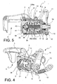
- a caliper for a vehicle disc brake is generally indicated with the reference number 1.
- the caliper 1 being preferably, but not necessarily, of the floating type, comprises a parking device 2 adapted to carry out a parking braking action of the vehicle, being able to be operated by the vehicle driver, for example, by actuating the so-called hand brake.
- the caliper 1 is so shaped as to be able to perform, besides the parking braking, also the service braking action, that is, the braking action which is applied on the moving vehicle, for example, by actuating the brake pedal.
- the caliper 1 comprises a body 3 defining a disc space 4 which is adapted to at least partially receive a brake disc (not shown in the Figures) associated to a vehicle wheel. On at least one, preferably on both the disc space 4 sides, the body 3 defines pads seats 5 adapted to receive one or more pads (not shown in the Figures) suitable to engage the brake disc, by clamping it and thereby implementing the braking action.
- the parking device 2 comprises a main supporting body 6 which is preferably manufactured in a single piece with the body 3 but which, alternatively, could be separated therefrom, and connectable thereto.
- the parking device 2 comprises pushing means 7 adapted to exert a pushing action on at least one of the caliper 1 pads so that the caliper engages the brake disc.
- the parking device 2 further comprises actuating means 8 adapted to operate the pushing means 7, so that the latter exert the above-cited pushing action on the pad, and a reaction portion 9, for example, a reaction member 9 which preferably is connected or connectable to the actuating device 2 main supporting body 6 at a supporting portion 10 thereof.
- a reaction member 9 which preferably is connected or connectable to the actuating device 2 main supporting body 6 at a supporting portion 10 thereof.
- Such reaction member 9 is suitable to cooperate with the actuating means 8 so that the latter can perform the pushing means 7 actuation.
- the cooperation modes between reaction member 9 and pushing means 7 will be set forth in detail herein below.
- the parking device 2 actuating means 8 comprise an actuating lever 11 connectable, for example, to a hand brake lever within the vehicle (not shown in the Figures).
- the actuating lever 11 is connected to the main supporting body 6 so as to be able to perform rotations, and preferably slight translations, relative to it.
- the actuating lever 11 can change from a rest position, corresponding to the lowered hand brake position (absence of parking braking), to an operative position, corresponding to the lifted hand brake position (presence of the parking braking).
- a return spring 12 can be connected to the actuating lever 11, which is adapted to elastically stress the actuating lever towards the rest position. Such return spring 12 acts between the actuating lever 11 and the main supporting body 6, or a portion of a device integral thereto, for example, a contrast member 13 removably connected to the main supporting body 6.
- the actuating means 8 comprise an actuating shaft 14 capable to rotate and/or slide relative to the main supporting body 6.
- the actuating shaft 14 is advantageously integrally connected upon rotating with the actuating lever 11.
- the actuating means further comprise a main cup 15.
- the main cup 15 is separated from the actuating shaft 14, and connected or connectable thereto in a rotatably integral manner.
- the main cup 15 is preferably made of sinterized steel, while the actuating shaft 14 is preferably made of pressed steel.
- the main cup 15 comprises a cooperation side 15a, advantageously provided with rolling seats 16 adapted to at least partially receive rolling bodies, preferably balls, 17 and a to make them to roll therein, and a check side 15b opposite the cooperation side 15a, and preferably facing the pushing means 7.
- the reaction member 9 comprises a reaction cup 18 facing the main cup 15.
- the reaction cup 18 comprises a cooperation surface 19 which, in turn, comprises rolling seats 20 suitable to at least partially receive the balls 17 and to allow a rolling thereof within the rolling seats 20. Therefore, the balls 17 are interposed between the main cup 15 and the reaction cup 18, being housed concomitantly in the respective rolling seats 16 and 20 thereof.
- main cup 15 the rolling seats 16 and the reaction cup 18 rolling seats 20 are shaped so that, when the balls 17, interposed between the caps 15 and 18, concomitantly roll in such rolling seats 16 and 20, main cup 15 and reaction cup 18 are urged to spread apart.
- the reaction member 9 reaction cup 18 forms means for the connection with a supporting device 21 adapted to support the pushing means 7.
- the reaction cup 18 can form radically projecting portions 22 which define connecting seats 23 therebetween for the reaction member 9 connection with the supporting device 21, for example, by elastic legs 25 of a cage 24 which is snap-connectable to the reaction cup 18.
- the cage 24 reaction member 9 turn out to be mutually integrally connected upon rotating and translating.
- the cage 24 supports a pushing shaft 26 operatively connected to the main cup 15. Such pushing shaft 26 is free to slide relative to the cage 24, upon interaction with the main cup 15.
- the main cup 15 rototranslation which is triggered according to the modes described by the actuating lever 11 rotation, results in a translation of the pushing shaft 26, which translates, thus moving away from the reaction member 9, that is, thus approaching to the disc space 4.
- a contrast spring 28 can act so arranged as to elastically urge the pushing shaft 26 towards the main cup 15.
- means anti-friction can be arranged therebetween, for example, a Teflon-coated fifth wheel 29.
- At least one pushing shaft 26 portion is integral upon rotation with the cage 24.
- anti-rotation means are provided in which, for example, the cage 24 defines a shaft seat 27 having an outline which is essentially complementary to the outline of a pushing shaft 26 portion, for example, an outline provided with a plurality of lobes, which is adapted to implement a shape-coupling between pushing shaft 26 and cage 24.
- a pushing shaft 26 end opposite the main cup 15 inserts into a piston 34 recess 33, so as to push it against the pad, upon the action exerted by the actuation means on the pushing shaft.
- the pushing shaft 26 is obtained by means of two coupled components to form a screw/nut screw coupling, in order to allow the pad wear automatic recovery by creating a pushing shaft 26 of a length which increases proportionally to the pad wear.
- the other component is arranged on the piston side 34, and inserts into the recess 33 with interposition of an elastic pushing member 36 adapted to exert a thrust on such component towards the same piston and the disc space 4.
- the pushing shaft 26 comprises a bush 26a arranged on the actuating means 8 side and defining the above-mentioned first component.
- Such bush 26a comprises a base portion 126a adapted to define a supporting and abutment member for the contrast spring 28, and a supporting surface for the fifth wheel 29, where present.
- the bush 26a further comprises a shaped portion 226a adapted to pass through the cage 24 shaft seat 27, for example, thus implementing the above-mentioned shape-coupling.
- the shaped portion 226a has a counter-shaped section with the shaft seat 27, for example, a lobe-shaped section.
- the bush 26a further defines a threaded seat 30 adapted to receive a threaded pin 31 which defines the above-mentioned pushing shaft 26 second component.
- the threaded seat 30 can be advantageously through portion, thus opening onto both ends of the bush 26a, on the actuating means side 8 and the piston side 34, respectively.
- a pushing head 32 can be provided which is adapted to fit in a corresponding head seat 33a of the piston 34 recess 33.
- the pushing head 32 has higher radial or transversal dimensions than the threaded pin 31, and preferably comprises a frusto-conical portion 32a adapted to abut against a corresponding head seat 33a frusto-conical portion 33b.
- a front axial enlargement 32b can be advantageously provided, which is adapted to insert in a corresponding cylindrical front portion 33c of the head seat 33a, for example, by interposition of a seal ring 39.
- the front axial enlargement 32b has lower transversal or radial dimensions than the frusto-conical portion 32a and, as a result, the head seat 33a cylindrical front portion 33c has lower transversal or radial dimensions than the head seat 33a frusto-conical portion 33b.
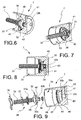
- the pushing head 32 and, un particular, the frusto-conical portion 32a has at least one notch 40 ( Figs. 6-9 ) opening onto both sides facing the actuating means 8 and the disc space 4, respectively.
- more notches 40 are provided, preferably distributed along the frusto-conical portion side surface.
- the piston 34 is mounted on the caliper 1 so as to be able to slide within a piston seat 35 defined by the main supporting body 6.
- the elastic pushing member 36 acts between pushing head 32 and piston 34, keeping the pushing head 32 pressed in the head seat 33a
- the pushing shaft 26 translation results in a translation of the piston 34 which interacts with at least one of the above-cited pads, thus being pushed against the brake disc housed in the disc space 4.
- the pushing shaft 26 and, particularly, the threaded pin 31 shape plays the advantageous function to recover the clearances due to the wearing of the pads, which clearances are compensated by rotations thereof within the bush 26a threaded seat 30.
- the pushing head 32 can rotate relative to the elastic pushing member 36.
- anti-friction means are interposed between the latter, for example, a washer 37 and/or a bearing 37a.
- the actuating shaft advantageously comprises a hole 38 adapted to at least partially receive the threaded pin 31.
- the recess 33 internally defined by the piston 34, beside at least partially receiving the pushing means 7, is suitable to be filled with a pressurized liquid, so that the piston 34 can be hydraulically operated as well, that is, for the service braking action, actuatable for example by depressing the brake pedal.
- the piston 34 can advantageously comprise a compensating duct 41 opening onto the recess 33, on a side, and on the piston outer surface, on the other side, preferably at an annular seat 42 adapted to receive an end of a non-shown dust cover.
- the compensating duct 41 opens out in the recess 33 at the cylindrical front portion 33c of the head seat 33a, in a chamber 43 defined by the axial front enlargement 32b of the pushing head 32, where provided.
- the piston 34 recess 33 has a notch 44 which is adapted to receive at least one attachment portion 45 of the elastic pushing member 36.
- notch 44 is advantageously arranged upstream the head seat 33a according to the translation direction upon braking of the parking device.
- the notch 44 has a continuous annular shape, but a discontinuous annular notch can be also provided, which is complementary to the elastic pushing member 36 shape, as it will be described by way of example herein below.
- the recess 33 has a preferably cylindrical connection portion 46 arranged between annular notch 44 and head seat 33a.
- the recess 33 has a preferably frusto-conical inserting portion 47 arranged upstream the annular notch 44 according to the translation direction upon braking of the parking device.
- an inlet portion 48 can be provided still more upstream, for example, an essentially cylindrical inlet portion.
- the elastic pushing member 36 comprises at least one attachment portion 45 adapted to directly insert in the notch 44, as a result avoiding the presence of check rings.
- the elastic pushing member 36 further comprises at least one active portion 49 extending from the attachment portion 45 and which is adapted to abut upon pushing on the threaded pin 31, particularly on the pushing head 32, where present.
- the elastic pushing member 36 further comprises at least one elastic portion 50, in the strict sense of the word, interposed between attachment portion 45 and active portion 49.
- attachment portion 45 and active portion 49 have a circumferential extension around an axial direction X which, in the assembled configuration of the caliper, coincides with a translation direction of the parking device 2.
- attachment portion 45 and active portion 49 are arranged at different levels, with reference to the axial direction X, and the elastic portion 50 advantageously extends according to an inclined direction relative to the axial direction X.
- attachment portion 45 and active portion 49 have different transversal or radial dimensions as regards the axial direction X which, in the assembled configuration of the caliper, coincides with a translation direction of the parking device 2.
- the attachment portion 45 has a higher transversal or radial dimensions than the active portion 49 transversal or radial dimensions.
- attachment portion 45 and active portion 49 at least theoretically define two circumferences A, B of a different diameter.
- the elastic pushing member 36 shape at least theoretically defines a frusto-conical surface along the axial direction X.
- the elastic pushing member 36 is implemented by an extended body, for example a metal wire, sheet, or web, which is folded to obtain attachment portion 45, elastic portion 50, and active portion 49.
- an extended body for example a metal wire, sheet, or web
- two or more attachment portions and two or more active portions are provided which are formed sequentially along the extended body around the axial direction X, that is, circumferentially distributed around the axial direction X, and interspersed with respective elastic portions.
- each active portion 49 has an arched extension preferably, lying on a single circumference.
- each attachment portion 45 has an arched extension preferably lying on a further single circumference which is larger than the circumference which the active portions 49 lie on.
- the elastic portions have a rectilinear extension.
- the extended body comprises first connecting lengths 51 interposed between an attachment portion 45 and an elastic portion 50, and second connecting lengths 52 interposed between an elastic portion 50 and an active portion 49.
- the extended body has distinct -that is not matching- ends Y and Z, which are preferably arranged at a preset distance. According to the example illustrated in the Figures, the two ends Y and Z are arranged at an attachment portion, which in this manner turns out to be partially interrupted.
- the elastic pushing member shape and configuration allow reducing the number of components required, by omitting a check ring. Furthermore, the elastic pushing member allows a homogeneous distribution of the thrust on the head, thus eliminating the risks for stick-slip of the threaded pin.
- the piston shape also promotes the elastic pushing member assembling, by allowing a direct insertion, without the need to use check rings, for example, further promoted by the conical shape of an insertion portion of the inner recess to the same piston.
- the elastic pushing member can be implemented by a folded and cut sheet.
- the piston notch 44 has a discontinuous annular shape which is adapted to receive the elastic pushing member active portions.
- the elastic portions 50 can be implemented by arcs of circumference.
Landscapes
- Engineering & Computer Science (AREA)
- General Engineering & Computer Science (AREA)
- Mechanical Engineering (AREA)
- Braking Arrangements (AREA)
Claims (24)
- Elastisches Drückelement (36) für einen kombinierten oder hydromechanischen Scheibenbremssattel (1) mit automatischem Ausgleichen des Belagverschleißes,
wobei das elastische Drückelement (36) dazu geeignet ist, zwischen einem Kolben (34) des Bremssattels (1) und einer Komponente (31) einer Drückwelle (26) angeordnet zu sein,
wobei das elastische Drückelement (36) ferner umfasst:- wenigsten einen Befestigungsabschnitt (45),- wenigstens einen aktiven Abschnitt (49), welcher sich von dem Befestigungsabschnitt (45) erstreckt,- ferner umfassend wenigstens einen elastischen Abschnitt (50), im eigentlichen Sinne des Wortes, welcher zwischen dem Befestigungsabschnitt (45) und dem aktiven Abschnitt (49) angeordnet ist,- wobei der Befestigungsabschnitt (45) und der aktive Abschnitt (49) eine Umfangsausdehnung um eine Axialrichtung (X) aufweisen, welche in der zusammengebauten Konfiguration des Bremssattels mit einer Translationsrichtung einer Parkvorrichtung (2) übereinstimmt,dadurch gekennzeichnet, dass- jeder aktive Abschnitt (49) eine bogenförmige Ausdehnung aufweist, welche auf einem einzelnen Umfang liegt, und- jeder Befestigungsabschnitt (45) eine bogenförmige Ausdehnung aufweist, welche auf einem weiteren einzelnen Umfang liegt, welcher größer ist, als der Umfang, auf welchem die aktiven Abschnitte (49) liegen. - Elastisches Drückelement (36) nach Anspruch 1,
wobei der Befestigungsabschnitt (45) und der aktive Abschnitt (49) in unterschiedlichen Ebenen relativ zur Axialrichtung (X) angeordnet sind und wobei der elastische Abschnitt (50) sich vorteilhafterweise gemäß einer geneigten Richtung relativ zur Axialrichtung (X) erstreckt. - Elastisches Drückelement (36) nach Anspruch 1 oder 2,
wobei der Befestigungsabschnitt (45) und der aktive Abschnitt (49) unterschiedliche transversale oder radiale Abmessungen im Vergleich zur Axialrichtung (X) aufweisen. - Elastisches Drückelement (36) nach Anspruch 3, wobei der Befestigungsabschnitt (45) eine höhere transversale oder radiale Abmessung als die transversale oder radiale Abmessung des aktiven Abschnitts (49) aufweist.
- Elastisches Drückelement (36) nach einem der Ansprüche 1 bis 4,
wobei der Befestigungsabschnitt (45) und der aktive Abschnitt (49) zwei Umfänge (A, B) mit einem unterschiedlichen Durchmesser definieren. - Elastisches Drückelement (36) nach einem der vorhergehenden Ansprüche, wobei die Form des elastischen Drückelements (36) wenigstens theoretisch eine kegelstumpfförmige Fläche entlang einer Axialrichtung (X) definiert, welche in der zusammengebauten Konfiguration des Bremssattels mit einer Translationsrichtung einer Parkvorrichtung (2) übereinstimmt.
- Elastisches Drückelement (36) nach einem der vorhergehenden Ansprüche, wobei das elastische Drückelement (36) durch einen gefalteten ausgestreckten Körper implementiert ist oder/und
wobei das elastische Drückelement (36) durch einen ausgestreckten Körper implementiert ist, welcher aus einem Draht, einem Blech oder einem Netz aus Metall ausgewählt ist, oder/und
wobei zwei oder mehrere Befestigungsabschnitte (45) und zwei oder mehrere aktive Abschnitte (49) bereitgestellt sind, welche entlang des ausgestreckten Körpers um eine Axialrichtung (X) aufeinanderfolgend gebildet sind und mit jeweiligen elastischen Abschnitten (50) durchsetzt sind. - Elastisches Drückelement (36) nach Anspruch 7,
wobei zwei oder mehrere Befestigungsabschnitte (45) und zwei oder mehrere aktive Abschnitte (49) bereitgestellt sind, welche entlang des ausgestreckten Körpers aufeinanderfolgend gebildet sind und mit jeweiligen elastischen Abschnitten (50) durchsetzt sind und am Umfang um eine Axialrichtung (X) verteilt sind. - Elastisches Drückelement (36) nach einem der Ansprüche 7 bis 8,
wobei jeder aktive Abschnitt (49) eine bogenförmige Ausdehnung aufweist, welche vorzugsweise auf einem einzelnen Umfang (B) liegt. - Elastisches Drückelement (36) nach Anspruch 9,
wobei jeder Befestigungsabschnitt (45) eine bogenförmige Ausdehnung aufweist, welche vorzugsweise auf einem einzelnen Umfang (A) liegt, welcher höher ist, als der Umfang, auf welchem die aktiven Abschnitte (49) liegen. - Elastisches Drückelement (36) nach Anspruch 9 oder 10,
wobei die elastischen Abschnitte (50) eine geradlinige Ausdehnung aufweisen. - Elastisches Drückelement (36) nach einem der Ansprüche 7 bis 11,
wobei der ausgestreckte Körper wenigstens eine erste Verbindungslänge (51) aufweist, welche zwischen einem Befestigungsabschnitt (45) und einem elastischen Abschnitt (50) angeordnet ist, und wenigstens eine zweite Verbindungslänge (52) aufweist, welche zwischen einem elastischen Abschnitt (50) und einem aktiven Abschnitt (49) angeordnet ist. - Elastisches Drückelement (36) nach einem der Ansprüche 7 bis 12,
wobei der ausgestreckte Körper eindeutige Enden (Y, Z) aufweist oder/und wobei die Enden (Y, Z) des ausgestreckten Körpers an einer vorgegebenen Entfernung angeordnet sind oder/und
wobei die zwei Enden (Y, Z) an einem Befestigungsabschnitt (45) angeordnet sind, welcher somit sich als teilweise unterbrochen erweist. - Kolben (34) für einen kombinierten oder hydromechanischen Scheibenbremssattel (1) mit automatischem Ausgleichen des Belagverschleißes, wobei der Kolben ein elastisches Drückelement (36) nach wenigstens einem der Ansprüche 1 bis 13 umfasst.
- Kolben (34) nach Anspruch 14,
wobei der Kolben eine Aussparung (33) aufweist, welche dazu geeignet ist, ein Ende einer Komponente der Drückwelle (26) aufzunehmen, wobei die Aussparung (33) eine Einbuchtung (44) aufweist, welche dazu geeignet ist, wenigstens einen Befestigungsabschnitt (45) des elastischen Drückelements (36) aufzunehmen. - Kolben (34) nach Anspruch 15,
wobei die Einbuchtung (44) eine durchgehende Ringform aufweist. - Kombinierter oder hydromechanischer Bremssattel (1) einer Scheibenbremse mit automatischem Ausgleichen des Belagverschleißes, umfassend einen Kolben (34) nach einem oder mehreren der Ansprüche 14 bis 16.
- Bremssattel (1) nach Anspruch 17,
umfassend einen Gewindestift (31) eines Drückmittels (7), wobei an einem Ende des Gewindestifts (31), welches einem Scheibenraum (4) und dem Kolben (34) zugewandt ist, ein Drückkopf (32) bereitgestellt ist, welcher dazu geeignet ist, in eine entsprechende Kopfauflage (33a) der Aussparung (33) des Kolbens (34) einzugreifen. - Bremssattel (1) nach Anspruch 17 oder 18,
wobei der Drückkopf (32) größere radiale oder transversale Abmessungen, als der Gewindestift (31) aufweist und vorzugsweise einen kegelstumpfförmigen Abschnitt (32a) umfasst, welcher zur Anlage mit einem entsprechenden kegelstumpfförmigen Abschnitt (33b) der Kopfauflage (33a) geeignet ist, oder/und
wobei der Drückkopf (32) eine axiale vordere Aufweitung (32b) umfasst, welche dazu geeignet ist, in einen entsprechenden zylindrischen Vorderabschnitt (33c) der Kopfauflage (33a) unter Zwischenschaltung eines Dichtungsrings (39) eingeführt zu werden, oder/und wobei die axiale vordere Aufweitung (32b) kleinere transversale oder radiale Abmessungen, als der kegelstumpfförmige Abschnitt (32a) aufweist und der zylindrische Vorderabschnitt (33c) der Kopfauflage (33a) kleinere transversale oder radiale Abmessungen, als der kegelstumpfförmige Abschnitt (33b) der Kopfauflage (33a) aufweist. - Bremssattel (1) nach einem der Ansprüche 17 bis 19,
wobei ein Drückkopf (32) und insbesondere ein kegelstumpfförmiger Abschnitt (32a) des Gewindestifts (31) wenigstens eine zu beiden Seiten offene Einbuchtung (40) aufweist. - Bremssattel (1) nach einem der Ansprüche 17 bis 20,
wobei das elastische Drückelement (36) zwischen dem Drückkopf (32) und dem Kolben (34) eingreift, wodurch der Drückkopf (32) in der Kopfauflage (33a) gedrückt gehalten ist, oder/und
wobei Antireibungsmittel, beispielsweise eine Scheibe (37) oder/und ein Lager (37a), zwischen dem elastischen Drückelement (36) und dem Drückkopf (32) eingefügt sind. - Bremssattel (1) nach einem der Ansprüche 17 bis 21,
umfassend eine Betätigungswelle eines Betätigungsmittels (8), wobei die Betätigungswelle eine Öffnung (38) umfasst, welche dazu geeignet ist, den Gewindestift (31) wenigstens teilweise aufzunehmen, oder/und umfassend eine Drückwelle (26) eines Drückmittels (7), wobei die Drückwelle eine Buchse (26a) umfasst, welche mit einer Auflage (30) für einen Gewindestift (31) vorgesehen ist, wobei die Auflage (30) zu beiden Seiten der Buchse (26a) offen ist. - Elastisches Drückelement (36) nach Anspruch 1 oder 9 oder 10, wobei die elastischen Abschnitte (50) eine bogenförmige Umfangsausdehnung aufweisen.
- Elastisches Drückelement (36) nach Anspruch 1,
wobei der wenigstens eine Befestigungsabschnitt (45) dazu geeignet ist, direkt in eine Einbuchtung (44) des Kolbens (34) eingeführt zu werden.
Applications Claiming Priority (2)
| Application Number | Priority Date | Filing Date | Title |
|---|---|---|---|
| IT001598A ITMI20071598A1 (it) | 2007-08-02 | 2007-08-02 | Elemento elastico di spinta di una pinza combinata |
| PCT/IT2008/000490 WO2009016675A1 (en) | 2007-08-02 | 2008-07-18 | Pushing elastic member for a combined caliper |
Publications (2)
| Publication Number | Publication Date |
|---|---|
| EP2191160A1 EP2191160A1 (de) | 2010-06-02 |
| EP2191160B1 true EP2191160B1 (de) | 2011-08-10 |
Family
ID=39944433
Family Applications (1)
| Application Number | Title | Priority Date | Filing Date |
|---|---|---|---|
| EP08790071A Active EP2191160B1 (de) | 2007-08-02 | 2008-07-18 | Elastisches druckglied für einen kombinierten sattel |
Country Status (4)
| Country | Link |
|---|---|
| EP (1) | EP2191160B1 (de) |
| AT (1) | ATE519960T1 (de) |
| IT (1) | ITMI20071598A1 (de) |
| WO (1) | WO2009016675A1 (de) |
Cited By (1)
| Publication number | Priority date | Publication date | Assignee | Title |
|---|---|---|---|---|
| WO2025016681A1 (fr) * | 2023-07-19 | 2025-01-23 | Hitachi Astemo France | Dispositif de freinage amélioré à tête de poussée mobile pour frein à étrier |
Families Citing this family (3)
| Publication number | Priority date | Publication date | Assignee | Title |
|---|---|---|---|---|
| US9328785B2 (en) | 2013-03-15 | 2016-05-03 | Hb Performance Systems, Inc. | Tensioned brake pad |
| GB2560763B (en) * | 2017-03-24 | 2021-10-27 | Liberty Vehicle Tech Limited | Brake calipers |
| IT202100027077A1 (it) | 2021-10-21 | 2023-04-21 | Brembo Spa | Pinza per freno a disco |
Citations (1)
| Publication number | Priority date | Publication date | Assignee | Title |
|---|---|---|---|---|
| WO2009016680A1 (en) * | 2007-08-02 | 2009-02-05 | Freni Brembo S.P.A. | Brake caliper parking device |
Family Cites Families (5)
| Publication number | Priority date | Publication date | Assignee | Title |
|---|---|---|---|---|
| US3767016A (en) | 1972-10-30 | 1973-10-23 | Gen Motors Corp | Brake actuator and adjuster mechanism |
| US3835961A (en) * | 1973-05-07 | 1974-09-17 | Dayton Walther Corp | Disk type brake |
| FR2600388B1 (fr) * | 1986-06-18 | 1988-09-09 | Bendix France | Moteur de frein comportant un dispositif de reglage automatique reinitialisable |
| US5038895A (en) * | 1988-10-24 | 1991-08-13 | Kelsey-Hayes Company | Automatic adjusting mechanism for a disc brake assembly having a mechanically actuated parking brake |
| JP4079916B2 (ja) * | 2003-08-13 | 2008-04-23 | 曙ブレーキ工業株式会社 | オーバアジャスト防止付き自動間隙調整機構を備えたブレーキ装置 |
-
2007
- 2007-08-02 IT IT001598A patent/ITMI20071598A1/it unknown
-
2008
- 2008-07-18 EP EP08790071A patent/EP2191160B1/de active Active
- 2008-07-18 WO PCT/IT2008/000490 patent/WO2009016675A1/en not_active Ceased
- 2008-07-18 AT AT08790071T patent/ATE519960T1/de not_active IP Right Cessation
Patent Citations (1)
| Publication number | Priority date | Publication date | Assignee | Title |
|---|---|---|---|---|
| WO2009016680A1 (en) * | 2007-08-02 | 2009-02-05 | Freni Brembo S.P.A. | Brake caliper parking device |
Cited By (1)
| Publication number | Priority date | Publication date | Assignee | Title |
|---|---|---|---|---|
| WO2025016681A1 (fr) * | 2023-07-19 | 2025-01-23 | Hitachi Astemo France | Dispositif de freinage amélioré à tête de poussée mobile pour frein à étrier |
Also Published As
| Publication number | Publication date |
|---|---|
| ITMI20071598A1 (it) | 2009-02-03 |
| ATE519960T1 (de) | 2011-08-15 |
| WO2009016675A1 (en) | 2009-02-05 |
| EP2191160A1 (de) | 2010-06-02 |
Similar Documents
| Publication | Publication Date | Title |
|---|---|---|
| US12104666B2 (en) | Brake caliper for disc brake | |
| JP6208065B2 (ja) | 対向ピストン型ディスクブレーキ装置 | |
| EP3153736B1 (de) | Belagbaugruppe für eine scheibenbremse | |
| US8544613B2 (en) | Disc braking system for a vehicle combining service and parking brake | |
| CA2516947A1 (en) | Disc brake for a vehicle, in particular a commercial vehicle | |
| JP6739287B2 (ja) | 電動ブレーキ装置 | |
| US6484852B1 (en) | Multiple disk brake system with integrated parking brake | |
| US10267369B2 (en) | Articulating brake piston cap for a brake assembly | |
| JP2019215067A (ja) | 対向ピストン型ディスクブレーキ装置 | |
| JP2017124706A (ja) | 電動ブレーキ装置 | |
| JP5122972B2 (ja) | ディスクブレーキ用キャリパー | |
| EP2191160A1 (de) | Elastisches druckglied für einen kombinierten sattel | |
| US7213688B2 (en) | Disc brake having at least two friction rings | |
| US20080164105A1 (en) | Electromechanical Disk Brake With Self-Boosting | |
| CN101802435A (zh) | 制动钳驻车装置 | |
| US20040200676A1 (en) | Electric sliding disc brake system | |
| EP1584833A2 (de) | Elektromechanische Scheibenbremse | |
| US12128861B2 (en) | Brake caliper for disc brake | |
| JP2020193641A (ja) | 車両用ブレーキ | |
| EP2183501B1 (de) | Bremssattelparkvorrichtung | |
| WO2005038287A1 (en) | Wear compensation system for a disk brake assembly | |
| JP6719916B2 (ja) | 電動ブレーキ装置および電動ブレーキ装置の製造方法 | |
| WO2017109152A1 (en) | Disc brake and method for manufacturing the same | |
| JP2013139848A (ja) | ディスクロータ及びディスクブレーキ装置 | |
| JP2013139847A (ja) | ディスクロータ及びディスクブレーキ装置 |
Legal Events
| Date | Code | Title | Description |
|---|---|---|---|
| PUAI | Public reference made under article 153(3) epc to a published international application that has entered the european phase |
Free format text: ORIGINAL CODE: 0009012 |
|
| 17P | Request for examination filed |
Effective date: 20100302 |
|
| AK | Designated contracting states |
Kind code of ref document: A1 Designated state(s): AT BE BG CH CY CZ DE DK EE ES FI FR GB GR HR HU IE IS IT LI LT LU LV MC MT NL NO PL PT RO SE SI SK TR |
|
| AX | Request for extension of the european patent |
Extension state: AL BA MK RS |
|
| RIN1 | Information on inventor provided before grant (corrected) |
Inventor name: RENZI, DAVIDE Inventor name: TERUZZI, ANDREA Inventor name: CANOVA, WALTER |
|
| 17Q | First examination report despatched |
Effective date: 20100707 |
|
| DAX | Request for extension of the european patent (deleted) | ||
| GRAP | Despatch of communication of intention to grant a patent |
Free format text: ORIGINAL CODE: EPIDOSNIGR1 |
|
| GRAS | Grant fee paid |
Free format text: ORIGINAL CODE: EPIDOSNIGR3 |
|
| GRAA | (expected) grant |
Free format text: ORIGINAL CODE: 0009210 |
|
| RIN1 | Information on inventor provided before grant (corrected) |
Inventor name: RENZI, DAVIDE Inventor name: TERUZZI, ANDREA Inventor name: CANOVA, WALTER |
|
| AK | Designated contracting states |
Kind code of ref document: B1 Designated state(s): AT BE BG CH CY CZ DE DK EE ES FI FR GB GR HR HU IE IS IT LI LT LU LV MC MT NL NO PL PT RO SE SI SK TR |
|
| REG | Reference to a national code |
Ref country code: GB Ref legal event code: FG4D |
|
| REG | Reference to a national code |
Ref country code: CH Ref legal event code: EP |
|
| REG | Reference to a national code |
Ref country code: IE Ref legal event code: FG4D |
|
| REG | Reference to a national code |
Ref country code: DE Ref legal event code: R096 Ref document number: 602008008801 Country of ref document: DE Effective date: 20111020 |
|
| REG | Reference to a national code |
Ref country code: NL Ref legal event code: VDEP Effective date: 20110810 |
|
| LTIE | Lt: invalidation of european patent or patent extension |
Effective date: 20110810 |
|
| PG25 | Lapsed in a contracting state [announced via postgrant information from national office to epo] |
Ref country code: NL Free format text: LAPSE BECAUSE OF FAILURE TO SUBMIT A TRANSLATION OF THE DESCRIPTION OR TO PAY THE FEE WITHIN THE PRESCRIBED TIME-LIMIT Effective date: 20110810 Ref country code: FI Free format text: LAPSE BECAUSE OF FAILURE TO SUBMIT A TRANSLATION OF THE DESCRIPTION OR TO PAY THE FEE WITHIN THE PRESCRIBED TIME-LIMIT Effective date: 20110810 Ref country code: HR Free format text: LAPSE BECAUSE OF FAILURE TO SUBMIT A TRANSLATION OF THE DESCRIPTION OR TO PAY THE FEE WITHIN THE PRESCRIBED TIME-LIMIT Effective date: 20110810 Ref country code: SE Free format text: LAPSE BECAUSE OF FAILURE TO SUBMIT A TRANSLATION OF THE DESCRIPTION OR TO PAY THE FEE WITHIN THE PRESCRIBED TIME-LIMIT Effective date: 20110810 Ref country code: NO Free format text: LAPSE BECAUSE OF FAILURE TO SUBMIT A TRANSLATION OF THE DESCRIPTION OR TO PAY THE FEE WITHIN THE PRESCRIBED TIME-LIMIT Effective date: 20111110 Ref country code: LT Free format text: LAPSE BECAUSE OF FAILURE TO SUBMIT A TRANSLATION OF THE DESCRIPTION OR TO PAY THE FEE WITHIN THE PRESCRIBED TIME-LIMIT Effective date: 20110810 Ref country code: PT Free format text: LAPSE BECAUSE OF FAILURE TO SUBMIT A TRANSLATION OF THE DESCRIPTION OR TO PAY THE FEE WITHIN THE PRESCRIBED TIME-LIMIT Effective date: 20111212 Ref country code: IS Free format text: LAPSE BECAUSE OF FAILURE TO SUBMIT A TRANSLATION OF THE DESCRIPTION OR TO PAY THE FEE WITHIN THE PRESCRIBED TIME-LIMIT Effective date: 20111210 |
|
| REG | Reference to a national code |
Ref country code: AT Ref legal event code: MK05 Ref document number: 519960 Country of ref document: AT Kind code of ref document: T Effective date: 20110810 |
|
| PG25 | Lapsed in a contracting state [announced via postgrant information from national office to epo] |
Ref country code: LV Free format text: LAPSE BECAUSE OF FAILURE TO SUBMIT A TRANSLATION OF THE DESCRIPTION OR TO PAY THE FEE WITHIN THE PRESCRIBED TIME-LIMIT Effective date: 20110810 Ref country code: CY Free format text: LAPSE BECAUSE OF FAILURE TO SUBMIT A TRANSLATION OF THE DESCRIPTION OR TO PAY THE FEE WITHIN THE PRESCRIBED TIME-LIMIT Effective date: 20110810 Ref country code: AT Free format text: LAPSE BECAUSE OF FAILURE TO SUBMIT A TRANSLATION OF THE DESCRIPTION OR TO PAY THE FEE WITHIN THE PRESCRIBED TIME-LIMIT Effective date: 20110810 Ref country code: PL Free format text: LAPSE BECAUSE OF FAILURE TO SUBMIT A TRANSLATION OF THE DESCRIPTION OR TO PAY THE FEE WITHIN THE PRESCRIBED TIME-LIMIT Effective date: 20110810 Ref country code: GR Free format text: LAPSE BECAUSE OF FAILURE TO SUBMIT A TRANSLATION OF THE DESCRIPTION OR TO PAY THE FEE WITHIN THE PRESCRIBED TIME-LIMIT Effective date: 20111111 Ref country code: SI Free format text: LAPSE BECAUSE OF FAILURE TO SUBMIT A TRANSLATION OF THE DESCRIPTION OR TO PAY THE FEE WITHIN THE PRESCRIBED TIME-LIMIT Effective date: 20110810 |
|
| PG25 | Lapsed in a contracting state [announced via postgrant information from national office to epo] |
Ref country code: BE Free format text: LAPSE BECAUSE OF FAILURE TO SUBMIT A TRANSLATION OF THE DESCRIPTION OR TO PAY THE FEE WITHIN THE PRESCRIBED TIME-LIMIT Effective date: 20110810 |
|
| PG25 | Lapsed in a contracting state [announced via postgrant information from national office to epo] |
Ref country code: CZ Free format text: LAPSE BECAUSE OF FAILURE TO SUBMIT A TRANSLATION OF THE DESCRIPTION OR TO PAY THE FEE WITHIN THE PRESCRIBED TIME-LIMIT Effective date: 20110810 Ref country code: SK Free format text: LAPSE BECAUSE OF FAILURE TO SUBMIT A TRANSLATION OF THE DESCRIPTION OR TO PAY THE FEE WITHIN THE PRESCRIBED TIME-LIMIT Effective date: 20110810 |
|
| PG25 | Lapsed in a contracting state [announced via postgrant information from national office to epo] |
Ref country code: EE Free format text: LAPSE BECAUSE OF FAILURE TO SUBMIT A TRANSLATION OF THE DESCRIPTION OR TO PAY THE FEE WITHIN THE PRESCRIBED TIME-LIMIT Effective date: 20110810 Ref country code: RO Free format text: LAPSE BECAUSE OF FAILURE TO SUBMIT A TRANSLATION OF THE DESCRIPTION OR TO PAY THE FEE WITHIN THE PRESCRIBED TIME-LIMIT Effective date: 20110810 |
|
| PLBE | No opposition filed within time limit |
Free format text: ORIGINAL CODE: 0009261 |
|
| STAA | Information on the status of an ep patent application or granted ep patent |
Free format text: STATUS: NO OPPOSITION FILED WITHIN TIME LIMIT |
|
| PG25 | Lapsed in a contracting state [announced via postgrant information from national office to epo] |
Ref country code: DK Free format text: LAPSE BECAUSE OF FAILURE TO SUBMIT A TRANSLATION OF THE DESCRIPTION OR TO PAY THE FEE WITHIN THE PRESCRIBED TIME-LIMIT Effective date: 20110810 |
|
| 26N | No opposition filed |
Effective date: 20120511 |
|
| REG | Reference to a national code |
Ref country code: DE Ref legal event code: R097 Ref document number: 602008008801 Country of ref document: DE Effective date: 20120511 |
|
| PGFP | Annual fee paid to national office [announced via postgrant information from national office to epo] |
Ref country code: FR Payment date: 20120816 Year of fee payment: 5 |
|
| PG25 | Lapsed in a contracting state [announced via postgrant information from national office to epo] |
Ref country code: MC Free format text: LAPSE BECAUSE OF NON-PAYMENT OF DUE FEES Effective date: 20120731 |
|
| REG | Reference to a national code |
Ref country code: CH Ref legal event code: PL |
|
| GBPC | Gb: european patent ceased through non-payment of renewal fee |
Effective date: 20120718 |
|
| PG25 | Lapsed in a contracting state [announced via postgrant information from national office to epo] |
Ref country code: CH Free format text: LAPSE BECAUSE OF NON-PAYMENT OF DUE FEES Effective date: 20120731 Ref country code: ES Free format text: LAPSE BECAUSE OF FAILURE TO SUBMIT A TRANSLATION OF THE DESCRIPTION OR TO PAY THE FEE WITHIN THE PRESCRIBED TIME-LIMIT Effective date: 20111121 Ref country code: GB Free format text: LAPSE BECAUSE OF NON-PAYMENT OF DUE FEES Effective date: 20120718 Ref country code: LI Free format text: LAPSE BECAUSE OF NON-PAYMENT OF DUE FEES Effective date: 20120731 |
|
| REG | Reference to a national code |
Ref country code: IE Ref legal event code: MM4A |
|
| PG25 | Lapsed in a contracting state [announced via postgrant information from national office to epo] |
Ref country code: BG Free format text: LAPSE BECAUSE OF FAILURE TO SUBMIT A TRANSLATION OF THE DESCRIPTION OR TO PAY THE FEE WITHIN THE PRESCRIBED TIME-LIMIT Effective date: 20111110 |
|
| PG25 | Lapsed in a contracting state [announced via postgrant information from national office to epo] |
Ref country code: IE Free format text: LAPSE BECAUSE OF NON-PAYMENT OF DUE FEES Effective date: 20120718 Ref country code: MT Free format text: LAPSE BECAUSE OF FAILURE TO SUBMIT A TRANSLATION OF THE DESCRIPTION OR TO PAY THE FEE WITHIN THE PRESCRIBED TIME-LIMIT Effective date: 20110810 |
|
| REG | Reference to a national code |
Ref country code: FR Ref legal event code: ST Effective date: 20140331 |
|
| PG25 | Lapsed in a contracting state [announced via postgrant information from national office to epo] |
Ref country code: TR Free format text: LAPSE BECAUSE OF FAILURE TO SUBMIT A TRANSLATION OF THE DESCRIPTION OR TO PAY THE FEE WITHIN THE PRESCRIBED TIME-LIMIT Effective date: 20110810 |
|
| PG25 | Lapsed in a contracting state [announced via postgrant information from national office to epo] |
Ref country code: FR Free format text: LAPSE BECAUSE OF NON-PAYMENT OF DUE FEES Effective date: 20130731 Ref country code: LU Free format text: LAPSE BECAUSE OF NON-PAYMENT OF DUE FEES Effective date: 20120718 |
|
| PG25 | Lapsed in a contracting state [announced via postgrant information from national office to epo] |
Ref country code: HU Free format text: LAPSE BECAUSE OF FAILURE TO SUBMIT A TRANSLATION OF THE DESCRIPTION OR TO PAY THE FEE WITHIN THE PRESCRIBED TIME-LIMIT Effective date: 20080718 |
|
| REG | Reference to a national code |
Ref country code: DE Ref legal event code: R081 Ref document number: 602008008801 Country of ref document: DE Owner name: BREMBO S.P.A., CURNO, IT Free format text: FORMER OWNER: FRENI BREMBO S.P.A., CURNO, BERGAMO, IT |
|
| P01 | Opt-out of the competence of the unified patent court (upc) registered |
Effective date: 20230526 |
|
| PGFP | Annual fee paid to national office [announced via postgrant information from national office to epo] |
Ref country code: DE Payment date: 20240719 Year of fee payment: 17 |
|
| REG | Reference to a national code |
Ref country code: DE Ref legal event code: R119 Ref document number: 602008008801 Country of ref document: DE |
|
| PG25 | Lapsed in a contracting state [announced via postgrant information from national office to epo] |
Ref country code: DE Free format text: LAPSE BECAUSE OF NON-PAYMENT OF DUE FEES Effective date: 20260203 |
|
| PGFP | Annual fee paid to national office [announced via postgrant information from national office to epo] |
Ref country code: IT Payment date: 20260506 Year of fee payment: 19 |