EP2191238B1 - Appareil et procédé pour mesurer des déplacements d'éléments déplaçables - Google Patents
Appareil et procédé pour mesurer des déplacements d'éléments déplaçables Download PDFInfo
- Publication number
- EP2191238B1 EP2191238B1 EP08789861.5A EP08789861A EP2191238B1 EP 2191238 B1 EP2191238 B1 EP 2191238B1 EP 08789861 A EP08789861 A EP 08789861A EP 2191238 B1 EP2191238 B1 EP 2191238B1
- Authority
- EP
- European Patent Office
- Prior art keywords
- machine
- displacement
- displaceable member
- sensible
- pulse generator
- Prior art date
- Legal status (The legal status is an assumption and is not a legal conclusion. Google has not performed a legal analysis and makes no representation as to the accuracy of the status listed.)
- Not-in-force
Links
Images
Classifications
-
- G—PHYSICS
- G01—MEASURING; TESTING
- G01D—MEASURING NOT SPECIALLY ADAPTED FOR A SPECIFIC VARIABLE; ARRANGEMENTS FOR MEASURING TWO OR MORE VARIABLES NOT COVERED IN A SINGLE OTHER SUBCLASS; TARIFF METERING APPARATUS; MEASURING OR TESTING NOT OTHERWISE PROVIDED FOR
- G01D5/00—Mechanical means for transferring the output of a sensing member; Means for converting the output of a sensing member to another variable where the form or nature of the sensing member does not constrain the means for converting; Transducers not specially adapted for a specific variable
- G01D5/12—Mechanical means for transferring the output of a sensing member; Means for converting the output of a sensing member to another variable where the form or nature of the sensing member does not constrain the means for converting; Transducers not specially adapted for a specific variable using electric or magnetic means
- G01D5/244—Mechanical means for transferring the output of a sensing member; Means for converting the output of a sensing member to another variable where the form or nature of the sensing member does not constrain the means for converting; Transducers not specially adapted for a specific variable using electric or magnetic means influencing characteristics of pulses or pulse trains; generating pulses or pulse trains
Definitions
- the present invention relates to apparatus and methods for measuring displacements of a displaceable member along a predetermined displacement path.
- the invention is described below particularly with respect to rotary displaceable members such as in rotary encoders, but may also be used with respect to linearly-displaceable members, such as in linear encoders.
- the displacement of rotary members is usually measured by counting the number of turns or revolutions experienced by the rotary member as well as fractions thereof, which fractions determine the resolution of the measurement apparatus.
- Turn counting is needed for example in absolute encoders mounted on motors, e.g., as explained in US Patent 6,628,741 by Netzer.
- Turn counting systems are used in rotary encoders to provide absolute position information of high precision even when there is an interruption of the power supply to the system and the shaft to be monitored has been turning during these power supply interruptions.
- Many absolute encoders use batteries in order to monitor and record the turn counting while external power is interrupted.
- the use of battery has a number of drawbacks.
- batteries have a limited life time.
- replacing a battery without losing the recorded turn counting requires special circuitry, for example a large capacitor, to back up the recorded data during the battery replacement, which circuitry results in additional cost of the encoder.
- batteries tolerate a limited range of temperatures, and therefore where the encoders are to be used in high temperature environments, the battery cannot be placed inside the encoder.
- Patents US 5,565,769 and US 5,714,882 describe systems that are able to count and register the number of turns of a shaft without a battery; however, these systems are sensitive to vibrations.
- Patent US 6,628,741B1 describes apparatus to implement a turns counter without a battery by using a reed relay; however reed relays are sensitive to vibrations, have a limited life time, and can be damaged or destroyed in case of high accelerations.
- Another drawback is that the amount of energy produced in order to count and store the number of turns is very small, which limits the system to the use of ferroelectric memories; unfortunately, these memories are not available in small sizes, and this again limits their application in encoders.
- An object of the present invention is to provide apparatus, and also a method, for measuring displacements of a displaceable member having advantages in one or more of the above respects.
- apparatus for measuring displacements of a displaceable member along a predetermined displacement path by counting periods of displacement thereof along said predetermined displacement path, said apparatus, comprising:
- the first and second machine-sensible elements are magnetic elements
- the pulse generator includes a coil, a magnetic core magnetically coupled to the coil, and a spring-mounting for the magnetic core causing the core to move from an initial position in one direction with respect to the coil when aligned with one of the second machine-sensible elements, and to be returned in the opposite direction by the spring to its initial position, whereby the coil generates a pulse during each such movement of the magnetic core.
- the displaceable member is a rotary member, and the counter counts the number of periods of rotation and fractions thereof of the rotary member.
- the displaceable member is a linearly-displaceable member, and the counter counts the number of periods of linear displacements and fractions thereof experienced by the displaceable member.
- a method for measuring displacements of a displaceable member along a predetermined displacement path, by counting periods of displacement thereof along said predetermined displacement path comprising:
- the apparatus and method of the present invention as briefly described above enable measuring the displacement of a displaceable member in a manner which does not require a battery, which uses standard electronic devices, and which is relatively insensitive to vibrations.
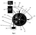
- FIG. 1 schematically illustrating one form of measuring apparatus constructed in accordance with the present invention for measuring the turns or rotations of a shaft 10 about a rotary axis 11.
- the apparatus illustrated in FIG. 1 may be in the form of a stand-alone turns counter, or a one-turn absolute encoder providing a precise measurement of the rotation angle of the shaft.
- the apparatus illustrated in FIG. 1 is designed for recording the number of turns and/or fractions of a turn, without the need for external power, since the required power is received from the rotating shaft by means of magnetic induction.
- the rotary shaft 10 itself, whose rotations are to be counted, or a separate disc fixed to that shaft, includes a first machine-sensible element 12 extending around the outer circumference of the shaft for a length defining one-half of a period of displacement (one rotation) of the shaft.
- machine-sensible element 12 covers one-half the circumference of shaft 10, leaving the other half uncovered. Accordingly, each full rotation or turn of shaft 10 is constituted of a single period, one-half of which is occupied by machine-sensible element 12, whereas the other half is not occupied by that element.
- the apparatus illustrated in FIG. 1 further includes at least one sensor, preferably two sensors, 13a, 13b, spaced from each other.
- Sensors 13a, 13b are located at sensing stations proximate to the displacement path of rotary shaft 10 so as to be capable of sensing the presence or absence of machine-sensible element 12 in the sensing station, and thereby of determining the status of the shaft 10 at any particular instant during the rotation of the shaft.
- machine-sensible element 12 is a magnetic element
- the two sensors 13a, 13b are Hall sensors spaced 90° from each other around the outer surface of shaft 10.
- the apparatus illustrated in FIG. 1 further includes a pulse generator, generally designated 14, fixed at another location, called a pulse generation station, proximate to the rotary shaft 10.
- Pulse generator 14 includes a magnetic core 14a mounted in cantilever fashion at one end of an elastic arm 14b, whose opposite end is fixed at 14c, and is movable with respect to a coil 14d to generate a pulse therein upon each movement of the core with respect to the coil.
- Shaft 10 further carries a plurality of second machine-sensible elements 15a-15d equally spaced in a circular array around the axis of rotation 11 of the shaft.
- Machine-sensible elements 15a-15d are also magnets, so as to attract magnetic core 14a of pulse generator 14 to generate in coil 14d a pulse each time a magnetic element 15a-15d moves proximately to, and away from, core 14a of the pulse generator.
- Each of the two sensors 13a, 13b is connected by leads 16a, 16b, and coil 14d of pulse generator 14 is connected by leads 17, to an electrical control circuit 18, which circuit controls a turns counter 19.
- the system illustrated in FIG. 1 operates as follows:
- the four magnets 15a-15d When shaft 10 rotates, the four magnets 15a-15d also rotate around rotary axis 11, such that each of the four magnets 15a-15d move towards, and then away from, core 14a of pulse generator 14. With each such movement of a magnet 15a-15d with respect to core 14a, the latter core is abruptly moved towards or away from coil 14d, to thereby generate a pulse within the coil with each such movement. These pulses are fed via lead 17 to the electrical control circuit 18. Each such pulse, generated in coil 14d and applied to electrical control circuit 18 via lead 17, activates the electrical circuit for a short period of time during which the electrical circuit enables sensors 13a, 13b to register the rotary position of shaft 10 at that instant.
- Sensors 13a, 13b thus serve as status sensors, determining the status of the shaft at any particular instant, namely the instant at which electrical circuit 18 receives a pulse from pulse generator 14.
- Electrical circuit 18 also controls a turns counter 19, which accumulates, in a non-volatile memory, the absolute position of the shaft by counting the number of periods (rotations) and functions thereof traversed by the shaft.
- magnets 15a-15d are spaced 90° from each other, the rotary position of the shaft can be determined with a resolution of one-quarter of a turn. Also, since there are two status sensors 13a, 13b, located 90° with respect to each other, the measuring system is able to distinguish the direction of the respective increment of rotation, i.e., whether in the forward direction or in the reverse direction.
- a pulse is outputted by the pulse generator 14 each time a magnet 15a-15d moves towards core 14a and then away from the core, and that each such pulse produced in core 14d is not linear, but sharply increases as the magnet moves towards the core, and sharply decreases as the magnet moves away from the core. It will be further seen that these movements of the core will generate energy to activate the turns counter 19.
- the amount of energy available from the pulse generator 14 is large enough to allow the storage of the shaft position in a non-volatile memory, like a ferroelectric memory, a flash memory, or an EPROM.
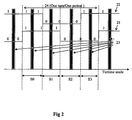
- FIG. 2 illustrates the sequence of states involved in the apparatus illustrated in FIG. 1 , wherein one turn to be counted is constituted of one period since there is only one magnet 12 extending for one-half the circumference of the shaft.
- Increment Table used to update the number of turns of the shaft in accordance with the sequence of states in FIG. 2 .
- Increment Table Sensor 1 13a
- Sensor 2 13b
- each sensor 13a, 13b is shown in FIG. 2 in relation to the rotation angle.
- the states of each sensor is represented by two values indicating whether the sensor is close to the sensible element or not. Whenever the electronic circuit 18 is activated, then each sensor state is sensed by the electronic circuit.
- FIG. 2 also shows, as grey areas 23, the range of angles when the pulse generator 14 outputs pulses to cause the electrical circuit 18 to activate the turns counters 19.
- a sector can be defined as a range of angles for which the state of sensors 13a, 13b is constant.
- four sector s0-s3 are defined in one turn 24, and the pulse generator outputs one pulse of energy between two transitions of the states 21 or 22.
- the electric circuit 18 and turns counter 19 are activated at least once each time shaft 10 moves at least one quarter of a turn, such that there will always be at least one update of the position measurement for each one quarter of a turn.
- Hall sensors are used because they provide sensing with minimum power consumption.
- other types of sensors can be used, such as reed relays, proximity sensors, or other types of sensors.
- the machine-sensible elements 12 and 15a-15d are magnetic elements which generate the required electricity and therefore do not need a battery.
- such elements could be optical elements, rather than magnetic elements, whereupon the status sensors 13a, 13b, as well the pulse generator 14, would be optically activated rather than magnetically activated.
- sectors in the preferred embodiment are shown covering a 90 degrees range of angle; however sectors can be of different sizes, so long as that there is at least one activation of the pulse generator in the range of each sensor.
- a particular advantage of the apparatus illustrated is that it does not count the number of pulses outputted by the pulse generator, but rather such pulses are used to provide energy to a separate turns counter 19.
- the described system is not sensitive to vibrations. If vibrations occur, and these vibrations result in a movement of the moving core 14a of the pulse generator 14, and a pulse of energy is outputted more than once in a quarter of a turn, then the increment by one quarter of a turn will be done only for the first pulse; the following pulse will result in a zero increment value.
- This is clearly shown in the above Increment Table, wherein the position increment is given as a function of the present states of the sensors and the previous states as sensed by the electronic circuit 18 and the turns counter 19.
- the electronic circuit 18 checks, at a high rate, the states of the sensors, and updates the shaft position according to the table. The checking cycle is short enough so that the shaft position will be updated even if the shaft has a high rotational speed.
- a sector is defined as a range of angles for which the state of sensors 13a and 13b remains constant.
- the preferred embodiment illustrated shows sectors of exactly one quarter of a turn; however the sectors may be of different sizes, as long as there is at least one activation of the pulse generator within one sector, i.e. at least one of the second sensible member activates the pulse generator within the sector range.
- the turn counting resolution is one-fourth of a turn, i.e., one-fourth of a period, using only two sensors.
- Another advantage of the illustrated apparatus is that only one magnetic energy generating element, i.e., pulse generator 14, is used for a bi-directional turn counter. This is to be sharply distinguished from the systems illustrated in the above-cited US Patents, which need at least three magnetic energy generating elements in order to count in both directions.
- the apparatus is used to count the number of turns of a shaft, each turn representing a period of displacement, with one-quarter of a turn resolution. It will be appreciated that the same apparatus can include a counting system having a different resolution than one-quarter turn by providing a different number of magnets 12 (or other machine-sensible elements), to thereby define a different number of sectors of the shaft to produce at least one pulse of energy per sector.
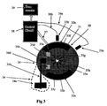
- FIG. 3 illustrates an apparatus wherein the shaft 30 is divided into eight sectors by eight magnets 35a-35h equally arranged in a circular array around the rotary axis 31 of the shaft.
- an inner magnet 35a-35d
- the apparatus illustrated in FIG. 3 includes a pulse generator, generally designated 34, including a movable core 34a secured to one end of an elastic member 34b whose opposite end 34c is fixed, and movable within a coil 34d when each of the inner magnets 35a-35h passes into and out of alignment with the magnetic core 34a.
- the pulses generated by coil 34d are applied to electrical circuit 38 via leads 37; and the status of each of the status sensors 33a, 33b, with respect to the outer magnets 32a, 32b, is fed to electrical circuit 38 via leads 36a and 36b from the two status sensors 33a, 33b.
- Electrical circuit 38 thus increments (or decrements) turns counter 39 according to the sensed status, as described above with respect to FIGs. 1 and 2 .
- FIG. 3 has a resolution of one-eighth of a turn, rather than one-quarter of a turn as in FIGs. 1 and 2 .
- a displacement measuring system constructed in accordance with the present invention may be based on more than one or two periods for each turn by providing the rotary shaft with the appropriate number of outer magnets (12), namely one for each such period and extending for one-half the distance of the respective period. It will also be appreciated that the apparatus may be constructed to provide a different number of sectors, and thereby a different resolution, by providing the appropriate number of inner magnets to actuate the pulse generator at least once for each sector during each rotation.
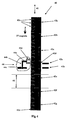
- FIG. 4 schematically illustrates the invention implemented in apparatus for measuring linear displacements in the form of linear displacement periods and fractions thereof along a linear displacement path, rather than rotary displacements as in FIGs. 1-3 .
- the apparatus illustrated in FIG. 4 includes a linearly-displaceable member, generally designated 40, displaceable in a linear path as indicated by arrow 41.
- Displaceable member 40 includes, on one side, a plurality of machine-sensible elements, namely magnets 42a-42g, one for each period of displacement of member 40, with each such magnet covering one-half the period.
- the respective side of displaceable member 40 further includes two status sensors 43a, 43b.
- pulse generator 44 including a movable core 44a carried at one end of an elastic arm 44b, with the opposite end of the elastic arm 44c fixedly mounted, and with the core 44a movable with respect to a coil 44d to generate an electrical pulse with each movement of the coil.
- pulse generator 44 is actuated by a plurality of magnets 45a-45n, corresponding to the number of periods defined by magnets 42a-42g and the resolution desired in the measuring apparatus.
- magnets 42a-42g divide the length of the displaceable member into seven periods 46
- the magnets 45a-45n divide each period 46 into four fractions, such that the measuring apparatus has a resolution of one-fourth period.
- the apparatus illustrated in FIG. 4 is otherwise constructed and operates in the same manner as described above with respect to FIGs. 1-3 , to measure the linear displacement of member 40 in terms of periods 46, with a resolution of one-fourth period. It will be appreciated that the distance of each period 46 is precisely known, so that the apparatus illustrated in FIG. 4 measures displacement in terms of absolute values of displacement.
- one or both of the types of machine-sensible elements could be optical elements or capacitive-type elements, rather than magnetic elements, and the pulse generator could be an optically-actuated one, rather than a magnetically-actuated one.
- the resolution of the measuring apparatus could be increased (or decreased) providing the appropriate number of magnets for actuating the pulse generator, and the appropriate spacing of the status sensors cooperable with the status magnets.
Landscapes
- Physics & Mathematics (AREA)
- General Physics & Mathematics (AREA)
- Measurement Of Length, Angles, Or The Like Using Electric Or Magnetic Means (AREA)
- Transmission And Conversion Of Sensor Element Output (AREA)
Claims (15)
- Appareil pour mesurer les déplacements d'un élément pouvant être déplacé (10, 30, 40) le long d'un trajet de déplacement prédéterminé en comptant les périodes de déplacement de celui-ci le long dudit trajet de déplacement prédéterminé, ledit appareil comprenant :un premier élément sensible à une machine (12, 32a, 42a) supporté par ledit élément pouvant être déplacé et occupant une longueur de celui-ci définissant seulement une partie d'une période de déplacement de l'élément pouvant être déplacé ;un premier capteur (13a, 33a, 43a) situé au niveau d'une station de détection à proximité dudit trajet de déplacement de manière à pouvoir détecter la présence ou l'absence dudit premier élément sensible à une machine dans la station de détection, et de ce fait déterminer l'état de l'élément pouvant être déplacé à n'importe quel instant particulier pendant le déplacement dudit élément pouvant être déplacé ;un générateur d'impulsions (14, 34, 44) situé au niveau d'une station de génération d'impulsions à proximité dudit trajet de déplacement ;une pluralité de deuxièmes éléments sensibles à une machine (15a-d, 35a-h, 45a-n) supportés par ledit élément pouvant être déplacé à des intervalles espacés le long de chaque période de déplacement de l'élément pouvant être déplacé, chacun desdits deuxièmes éléments sensibles à une machine étant utilisé pour actionner ledit générateur d'impulsions lors de son déplacement à travers ladite station de génération d'impulsions ;un compteur électrique (19, 39) pour compter les périodes de déplacement de l'élément pouvant être déplacé ; etun circuit électrique (18, 38) configuré pour être activé par ledit générateur d'impulsions, pendant une courte période de temps pendant laquelle le circuit électrique permet au premier capteur de détecter l'état de l'élément pouvant être déplacé à l'instant particulier auquel l'un desdits deuxièmes éléments sensibles à une machine passe à travers ladite station de génération d'impulsions, et pour incrémenter le compteur conformément à ladite détermination d'état, dans lequel ledit générateur d'impulsions est configuré pour générer une impulsion lors du déplacement de chacun de ladite pluralité de deuxièmes éléments sensibles à une machine soit vers ledit générateur d'impulsions, soit à l'opposé de celui-ci.
- Appareil selon la revendication 1, dans lequel ledit premier élément sensible à une machine est un élément magnétique.
- Appareil selon la revendication 1, dans lequel lesdits deuxièmes éléments sensibles à une machine sont des éléments magnétiques.
- Appareil selon la revendication 3, dans lequel ledit générateur d'impulsions comprend une bobine (14d, 34d, 44d), un noyau magnétique (14a, 34a, 44a) couplé magnétiquement à ladite bobine, et un montage à ressort (14b, 34b, 44b) pour ledit noyau magnétique, amenant ledit noyau à se déplacer à partir d'une position initiale dans une direction par rapport à ladite bobine lors de son alignement avec l'un desdits deuxièmes éléments sensibles à une machine, et à être ramené dans la direction opposée par ledit ressort à sa position initiale, moyennant quoi la bobine génère des impulsions pendant ces déplacements du noyau magnétique.
- Appareil selon la revendication 4, dans lequel ledit élément pouvant être déplacé peut être déplacé de manière bidirectionnelle, et ledit appareil comprend deux (13a-b, 33a-b, 43a-b) desdits premiers capteurs espacés l'un de l'autre le long dudit trajet de déplacement de manière à permettre au système de mesure de distinguer les déplacements dans la direction arrière des déplacements dans la direction avant.
- Appareil selon la revendication 5, dans lequel ledit circuit électrique incrémente ledit compteur électrique pour chaque déplacement dans la direction avant détecté, et décrémente ledit compteur électrique pour chaque déplacement dans la direction arrière détecté.
- Appareil selon la revendication 4, dans lequel ledit élément pouvant être déplacé supporte au moins quatre deuxièmes éléments sensibles à une machine (15a-d) espacés uniformément pour chaque période de déplacement, et un des premiers éléments sensibles à une machine (12) pour chaque période de déplacement s'étendant sur une moitié de la période de déplacement.
- Appareil selon la revendication 4, dans lequel ledit élément pouvant être déplacé supporte au moins huit deuxièmes éléments sensibles à une machine (35a-h) espacés uniformément définissant au moins deux périodes de déplacement, et deux desdits premiers éléments sensibles à une machine (32a-b) s'étendant chacun sur une moitié d'une période de déplacement.
- Appareil selon la revendication 4, dans lequel ledit élément pouvant être déplacé est l'un :d'un élément rotatif (10, 30), et ledit compteur compte le nombre de périodes de rotation et les fractions de celles-ci dudit élément rotatif ; etd'un élément pouvant être déplacé linéairement (40), et ledit compteur compte le nombre de périodes de déplacement linéaire et les fractions de celles-ci subies par l'élément pouvant être déplacé.
- Appareil selon la revendication 9, dans lequel au moins l'un :dudit élément pouvant être déplacé est un élément rotatif, et dans lequel ledit premier élément sensible à une machine est situé sur la surface périphérique extérieure dudit élément rotatif, et lesdits deuxièmes éléments sensibles à une machine sont situés en un ensemble circulaire autour de l'axe de rotation dudit élément rotatif ; etdudit élément pouvant être déplacé est un élément pouvant être déplacé linéairement, et dans lequel ledit premier élément sensible à une machine (42a) est situé le long d'un côté de l'élément pouvant être déplacé linéairement, et ladite pluralité de deuxièmes éléments sensibles à une machine (45a-n) sont situés du côté opposé dudit élément pouvant être déplacé linéairement (40).
- Appareil selon la revendication 1, dans lequel ledit générateur d'impulsions est configuré pour générer une impulsion lors du déplacement de chacun de ladite pluralité de deuxièmes éléments sensibles à une machine soit vers une bobine (14d, 34d, 44d), soit à l'opposé de celle-ci dans ledit générateur d'impulsions.
- Procédé pour mesurer les déplacements d'un élément pouvant être déplacé le long d'un trajet de déplacement prédéterminé en comptant les périodes de déplacement de celui-ci le long dudit trajet de déplacement prédéterminé, ledit procédé comprenant :l'application d'un premier élément sensible à une machine (12, 32a, 42a) au dit élément pouvant être déplacé pour qu'il occupe une longueur de celui-ci définissant seulement une partie d'une période de déplacement de l'élément pouvant être déplacé ;la prévision d'un premier capteur (13a, 33a, 43a) au niveau d'une station de détection à proximité dudit trajet de déplacement de manière à pouvoir détecter la présence ou l'absence dudit premier élément sensible à une machine dans la station de détection, et déterminer de ce fait l'état de l'élément pouvant être déplacé, à n'importe quel instant particulier pendant le déplacement dudit élément pouvant être déplacé ;le positionnement d'un générateur d'impulsions (14, 34, 44) au niveau d'une station de génération d'impulsions à proximité dudit trajet de déplacement ;l'application d'une pluralité de deuxièmes éléments sensibles à une machine (15a-d, 35a-h, 45a-n) au dit élément pouvant être déplacé à des intervalles espacés le long de chaque période de déplacement de l'élément pouvant être déplacé, chacun desdits deuxièmes éléments sensibles à une machine étant utilisé pour actionner ledit générateur d'impulsions lors de son déplacement à travers ladite station de génération d'impulsions ;la commande dudit générateur d'impulsions pour activer un circuit électrique (18, 38) pendant une courte période de temps pendant laquelle le circuit électrique actionne ledit premier capteur pour détecter l'état de l'élément pouvant être déplacé à l'instant particulier auquel l'un des deuxièmes éléments sensibles à une machine passe à travers ladite station de génération d'impulsions ; etl'incrémentation d'un compteur électrique (19, 39) conformément à ladite détermination d'état ; dans lequel ledit générateur d'impulsions est configuré pour générer une impulsion lors du déplacement de chacun de ladite pluralité de deuxièmes éléments sensibles à une machine soit vers ledit générateur d'impulsions, soit à l'opposé de celui-ci.
- Procédé selon la revendication 12, dans lequel ledit générateur d'impulsions comprend une bobine (14d, 34d, 44d), un noyau magnétique (14a, 34a, 44a) couplé magnétiquement à ladite bobine, et un montage à ressort (14b, 34b, 44b) pour ledit noyau magnétique, amenant ledit noyau à se déplacer à partir d'une position initiale dans une direction par rapport à ladite bobine lors de son alignement avec l'un desdits deuxièmes éléments sensibles à une machine, et à être ramené dans la direction opposée par ledit ressort à sa position initiale, moyennant quoi la bobine génère des impulsions pendant ces déplacements du noyau magnétique.
- Procédé selon la revendication 12, dans lequel ledit élément pouvant être déplacé peut être déplacé de manière bidirectionnelle, et il y a deux (13a-b, 33a-b, 43a-b) desdits premiers capteurs espacés l'un de l'autre le long de l'élément pouvant être déplacé de manière à permettre au système de mesure de distinguer les déplacements dans la direction arrière des déplacements dans la direction avant.
- Procédé selon la revendication 12, dans lequel ledit générateur d'impulsions est configuré pour générer une impulsion qui augmente alors que ledit un desdits deuxièmes éléments sensibles à une machine se déplace vers ledit générateur d'impulsions.
Applications Claiming Priority (2)
| Application Number | Priority Date | Filing Date | Title |
|---|---|---|---|
| US93585707P | 2007-09-04 | 2007-09-04 | |
| PCT/IL2008/001190 WO2009031142A2 (fr) | 2007-09-04 | 2008-09-03 | Appareil et procédé pour mesurer des déplacements d'éléments déplaçables |
Publications (2)
| Publication Number | Publication Date |
|---|---|
| EP2191238A2 EP2191238A2 (fr) | 2010-06-02 |
| EP2191238B1 true EP2191238B1 (fr) | 2016-08-17 |
Family
ID=40428002
Family Applications (1)
| Application Number | Title | Priority Date | Filing Date |
|---|---|---|---|
| EP08789861.5A Not-in-force EP2191238B1 (fr) | 2007-09-04 | 2008-09-03 | Appareil et procédé pour mesurer des déplacements d'éléments déplaçables |
Country Status (4)
| Country | Link |
|---|---|
| US (1) | US8461830B2 (fr) |
| EP (1) | EP2191238B1 (fr) |
| CN (1) | CN101918798B (fr) |
| WO (1) | WO2009031142A2 (fr) |
Families Citing this family (11)
| Publication number | Priority date | Publication date | Assignee | Title |
|---|---|---|---|---|
| CN101918798B (zh) | 2007-09-04 | 2014-01-15 | 亚斯卡瓦欧洲科技有限公司 | 用于测量可移置构件的位移的设备和方法 |
| WO2012025777A1 (fr) * | 2010-08-24 | 2012-03-01 | Aktiebolaget Skf | Procédé et système pour déterminer la position angulaire d'un élément rotatif, et palier comprenant un tel système |
| EP2562512A1 (fr) * | 2011-08-25 | 2013-02-27 | SICK STEGMANN GmbH | Codeur rotatif |
| DE112013002075T5 (de) * | 2012-04-17 | 2015-01-22 | Mitsubishi Electric Corp. | Multirotations-Drehgeber |
| CN107425671A (zh) * | 2016-05-23 | 2017-12-01 | 西门子公司 | 编码器及电机 |
| EP3494362A4 (fr) * | 2016-08-02 | 2020-03-11 | Servosense (SMC) Ltd. | Codeur absolu haute résolution |
| CN110622400B (zh) * | 2017-03-09 | 2021-10-08 | 伺服圣斯(Smc)有限公司 | 从移动元件中收集能量的脉冲发生器 |
| DE102022000345A1 (de) * | 2022-01-28 | 2023-08-03 | Baumer Germany Gmbh & Co. Kg | Vorrichtung zum Erfassen von Bewegungen und/oder Positionen eines Gegenstandes |
| DE102022000344B4 (de) * | 2022-01-28 | 2025-10-02 | Baumer Germany Gmbh & Co. Kg | Generator für einen Drehgeber sowie ein Drehgeber mit einem solchen Generator |
| DE102022000343B4 (de) * | 2022-01-28 | 2024-01-11 | Baumer Germany Gmbh & Co. Kg | Drehgeber mit Generator zur autarken Energieversorgung |
| DE102024102791A1 (de) * | 2024-01-31 | 2025-07-31 | CarByte GmbH | Sensor mit Energy Harvesting |
Family Cites Families (6)
| Publication number | Priority date | Publication date | Assignee | Title |
|---|---|---|---|---|
| EP0182322B1 (fr) * | 1984-11-20 | 1991-05-08 | Kabushiki Kaisha S.G. | Dispositif pour détecter des positions rotatives |
| CN85101440B (zh) * | 1985-04-01 | 1987-12-30 | 北京市清洁机械厂 | 具有计算机的位移测量设备 |
| EP0658745B1 (fr) * | 1993-12-02 | 1998-06-10 | Walter Dr. Mehnert | Capteur de position |
| US6628741B2 (en) | 2001-11-20 | 2003-09-30 | Netzer Precision Motion Sensors Ltd. | Non-volatile passive revolution counter with reed magnetic sensor |
| CN2767172Y (zh) * | 2005-03-03 | 2006-03-29 | 中国印钞造币总公司 | 号码机的全编码装置 |
| CN101918798B (zh) | 2007-09-04 | 2014-01-15 | 亚斯卡瓦欧洲科技有限公司 | 用于测量可移置构件的位移的设备和方法 |
-
2008
- 2008-09-03 CN CN200880114619.8A patent/CN101918798B/zh not_active Expired - Fee Related
- 2008-09-03 WO PCT/IL2008/001190 patent/WO2009031142A2/fr not_active Ceased
- 2008-09-03 EP EP08789861.5A patent/EP2191238B1/fr not_active Not-in-force
- 2008-09-03 US US12/676,156 patent/US8461830B2/en active Active
Also Published As
| Publication number | Publication date |
|---|---|
| CN101918798A (zh) | 2010-12-15 |
| US20100253327A1 (en) | 2010-10-07 |
| US8461830B2 (en) | 2013-06-11 |
| EP2191238A2 (fr) | 2010-06-02 |
| WO2009031142A2 (fr) | 2009-03-12 |
| CN101918798B (zh) | 2014-01-15 |
| WO2009031142A3 (fr) | 2009-05-14 |
Similar Documents
| Publication | Publication Date | Title |
|---|---|---|
| EP2191238B1 (fr) | Appareil et procédé pour mesurer des déplacements d'éléments déplaçables | |
| CA2696690C (fr) | Compteur de segments lineaires ou de tours a element ferromagnetique | |
| CN100468059C (zh) | 位置检测器 | |
| EP3430713B1 (fr) | Codeur de position | |
| JP5216462B2 (ja) | ロータリーエンコーダ及びその動作方法 | |
| JP6758436B2 (ja) | マルチターンアブソリュートエンコーダ、エンコード方法、コントローラ及び記憶媒体 | |
| KR20140143404A (ko) | 다회전 인코더 | |
| JP7412103B2 (ja) | エンコーダ装置 | |
| CN110622400B (zh) | 从移动元件中收集能量的脉冲发生器 | |
| EP0449037B1 (fr) | Transmetteur de position | |
| CN109952712B (zh) | 具有选择性磨损指示的滑环 | |
| US12566057B2 (en) | Method for initializing an angle-of-rotation measurement system, and angle-of-rotation measurement system | |
| US12449280B2 (en) | Sensor apparatus and operating method therefor | |
| JP2011133477A (ja) | 長さ測定装置 | |
| JP7430994B2 (ja) | エンコーダ装置 | |
| JP2024168473A (ja) | エンコーダ | |
| EP3098571B1 (fr) | Capteur de rotation non volatile avec une particule magnétique dans une piste en serpentin | |
| Zangl et al. | A non-contact multi-turn angular position sensor | |
| JPH049613A (ja) | 磁気エンコーダ | |
| JP2026513649A (ja) | 測定装置 | |
| CN121127727A (zh) | 用于对轴的旋转运动进行检测的绝对值旋转编码器 | |
| CN120077245A (zh) | 测量装置 | |
| JPS62276409A (ja) | ロ−タリエンコ−ダ | |
| JPS62263409A (ja) | エンコ−ダ | |
| KR890012061A (ko) | 게이트 혹은 이와 유사한 구조물의 판넬을 위한 가변 구동장치 |
Legal Events
| Date | Code | Title | Description |
|---|---|---|---|
| PUAI | Public reference made under article 153(3) epc to a published international application that has entered the european phase |
Free format text: ORIGINAL CODE: 0009012 |
|
| 17P | Request for examination filed |
Effective date: 20100406 |
|
| AK | Designated contracting states |
Kind code of ref document: A2 Designated state(s): AT BE BG CH CY CZ DE DK EE ES FI FR GB GR HR HU IE IS IT LI LT LU LV MC MT NL NO PL PT RO SE SI SK TR |
|
| AX | Request for extension of the european patent |
Extension state: AL BA MK RS |
|
| DAX | Request for extension of the european patent (deleted) | ||
| 17Q | First examination report despatched |
Effective date: 20140908 |
|
| GRAP | Despatch of communication of intention to grant a patent |
Free format text: ORIGINAL CODE: EPIDOSNIGR1 |
|
| INTG | Intention to grant announced |
Effective date: 20160310 |
|
| RAP1 | Party data changed (applicant data changed or rights of an application transferred) |
Owner name: YASKAWA EUROPE TECHNOLOGY LTD. |
|
| GRAS | Grant fee paid |
Free format text: ORIGINAL CODE: EPIDOSNIGR3 |
|
| GRAA | (expected) grant |
Free format text: ORIGINAL CODE: 0009210 |
|
| AK | Designated contracting states |
Kind code of ref document: B1 Designated state(s): AT BE BG CH CY CZ DE DK EE ES FI FR GB GR HR HU IE IS IT LI LT LU LV MC MT NL NO PL PT RO SE SI SK TR |
|
| REG | Reference to a national code |
Ref country code: GB Ref legal event code: FG4D |
|
| REG | Reference to a national code |
Ref country code: CH Ref legal event code: EP |
|
| REG | Reference to a national code |
Ref country code: IE Ref legal event code: FG4D |
|
| REG | Reference to a national code |
Ref country code: AT Ref legal event code: REF Ref document number: 821534 Country of ref document: AT Kind code of ref document: T Effective date: 20160915 |
|
| REG | Reference to a national code |
Ref country code: DE Ref legal event code: R096 Ref document number: 602008045755 Country of ref document: DE Ref country code: FR Ref legal event code: PLFP Year of fee payment: 9 |
|
| REG | Reference to a national code |
Ref country code: NL Ref legal event code: MP Effective date: 20160817 |
|
| REG | Reference to a national code |
Ref country code: LT Ref legal event code: MG4D |
|
| REG | Reference to a national code |
Ref country code: AT Ref legal event code: MK05 Ref document number: 821534 Country of ref document: AT Kind code of ref document: T Effective date: 20160817 |
|
| PG25 | Lapsed in a contracting state [announced via postgrant information from national office to epo] |
Ref country code: NO Free format text: LAPSE BECAUSE OF FAILURE TO SUBMIT A TRANSLATION OF THE DESCRIPTION OR TO PAY THE FEE WITHIN THE PRESCRIBED TIME-LIMIT Effective date: 20161117 Ref country code: FI Free format text: LAPSE BECAUSE OF FAILURE TO SUBMIT A TRANSLATION OF THE DESCRIPTION OR TO PAY THE FEE WITHIN THE PRESCRIBED TIME-LIMIT Effective date: 20160817 Ref country code: LT Free format text: LAPSE BECAUSE OF FAILURE TO SUBMIT A TRANSLATION OF THE DESCRIPTION OR TO PAY THE FEE WITHIN THE PRESCRIBED TIME-LIMIT Effective date: 20160817 Ref country code: IT Free format text: LAPSE BECAUSE OF FAILURE TO SUBMIT A TRANSLATION OF THE DESCRIPTION OR TO PAY THE FEE WITHIN THE PRESCRIBED TIME-LIMIT Effective date: 20160817 Ref country code: HR Free format text: LAPSE BECAUSE OF FAILURE TO SUBMIT A TRANSLATION OF THE DESCRIPTION OR TO PAY THE FEE WITHIN THE PRESCRIBED TIME-LIMIT Effective date: 20160817 Ref country code: NL Free format text: LAPSE BECAUSE OF FAILURE TO SUBMIT A TRANSLATION OF THE DESCRIPTION OR TO PAY THE FEE WITHIN THE PRESCRIBED TIME-LIMIT Effective date: 20160817 |
|
| PG25 | Lapsed in a contracting state [announced via postgrant information from national office to epo] |
Ref country code: LV Free format text: LAPSE BECAUSE OF FAILURE TO SUBMIT A TRANSLATION OF THE DESCRIPTION OR TO PAY THE FEE WITHIN THE PRESCRIBED TIME-LIMIT Effective date: 20160817 Ref country code: GR Free format text: LAPSE BECAUSE OF FAILURE TO SUBMIT A TRANSLATION OF THE DESCRIPTION OR TO PAY THE FEE WITHIN THE PRESCRIBED TIME-LIMIT Effective date: 20161118 Ref country code: PL Free format text: LAPSE BECAUSE OF FAILURE TO SUBMIT A TRANSLATION OF THE DESCRIPTION OR TO PAY THE FEE WITHIN THE PRESCRIBED TIME-LIMIT Effective date: 20160817 Ref country code: SE Free format text: LAPSE BECAUSE OF FAILURE TO SUBMIT A TRANSLATION OF THE DESCRIPTION OR TO PAY THE FEE WITHIN THE PRESCRIBED TIME-LIMIT Effective date: 20160817 Ref country code: PT Free format text: LAPSE BECAUSE OF FAILURE TO SUBMIT A TRANSLATION OF THE DESCRIPTION OR TO PAY THE FEE WITHIN THE PRESCRIBED TIME-LIMIT Effective date: 20161219 Ref country code: ES Free format text: LAPSE BECAUSE OF FAILURE TO SUBMIT A TRANSLATION OF THE DESCRIPTION OR TO PAY THE FEE WITHIN THE PRESCRIBED TIME-LIMIT Effective date: 20160817 Ref country code: BE Free format text: LAPSE BECAUSE OF NON-PAYMENT OF DUE FEES Effective date: 20160930 Ref country code: AT Free format text: LAPSE BECAUSE OF FAILURE TO SUBMIT A TRANSLATION OF THE DESCRIPTION OR TO PAY THE FEE WITHIN THE PRESCRIBED TIME-LIMIT Effective date: 20160817 |
|
| PG25 | Lapsed in a contracting state [announced via postgrant information from national office to epo] |
Ref country code: EE Free format text: LAPSE BECAUSE OF FAILURE TO SUBMIT A TRANSLATION OF THE DESCRIPTION OR TO PAY THE FEE WITHIN THE PRESCRIBED TIME-LIMIT Effective date: 20160817 Ref country code: RO Free format text: LAPSE BECAUSE OF FAILURE TO SUBMIT A TRANSLATION OF THE DESCRIPTION OR TO PAY THE FEE WITHIN THE PRESCRIBED TIME-LIMIT Effective date: 20160817 |
|
| REG | Reference to a national code |
Ref country code: CH Ref legal event code: PL |
|
| REG | Reference to a national code |
Ref country code: DE Ref legal event code: R097 Ref document number: 602008045755 Country of ref document: DE |
|
| PG25 | Lapsed in a contracting state [announced via postgrant information from national office to epo] |
Ref country code: SK Free format text: LAPSE BECAUSE OF FAILURE TO SUBMIT A TRANSLATION OF THE DESCRIPTION OR TO PAY THE FEE WITHIN THE PRESCRIBED TIME-LIMIT Effective date: 20160817 Ref country code: CZ Free format text: LAPSE BECAUSE OF FAILURE TO SUBMIT A TRANSLATION OF THE DESCRIPTION OR TO PAY THE FEE WITHIN THE PRESCRIBED TIME-LIMIT Effective date: 20160817 Ref country code: BG Free format text: LAPSE BECAUSE OF FAILURE TO SUBMIT A TRANSLATION OF THE DESCRIPTION OR TO PAY THE FEE WITHIN THE PRESCRIBED TIME-LIMIT Effective date: 20161117 Ref country code: BE Free format text: LAPSE BECAUSE OF FAILURE TO SUBMIT A TRANSLATION OF THE DESCRIPTION OR TO PAY THE FEE WITHIN THE PRESCRIBED TIME-LIMIT Effective date: 20160817 Ref country code: DK Free format text: LAPSE BECAUSE OF FAILURE TO SUBMIT A TRANSLATION OF THE DESCRIPTION OR TO PAY THE FEE WITHIN THE PRESCRIBED TIME-LIMIT Effective date: 20160817 |
|
| PLBE | No opposition filed within time limit |
Free format text: ORIGINAL CODE: 0009261 |
|
| STAA | Information on the status of an ep patent application or granted ep patent |
Free format text: STATUS: NO OPPOSITION FILED WITHIN TIME LIMIT |
|
| REG | Reference to a national code |
Ref country code: IE Ref legal event code: MM4A |
|
| PG25 | Lapsed in a contracting state [announced via postgrant information from national office to epo] |
Ref country code: MC Free format text: LAPSE BECAUSE OF FAILURE TO SUBMIT A TRANSLATION OF THE DESCRIPTION OR TO PAY THE FEE WITHIN THE PRESCRIBED TIME-LIMIT Effective date: 20160817 |
|
| 26N | No opposition filed |
Effective date: 20170518 |
|
| PG25 | Lapsed in a contracting state [announced via postgrant information from national office to epo] |
Ref country code: CH Free format text: LAPSE BECAUSE OF NON-PAYMENT OF DUE FEES Effective date: 20160930 Ref country code: LI Free format text: LAPSE BECAUSE OF NON-PAYMENT OF DUE FEES Effective date: 20160930 Ref country code: IE Free format text: LAPSE BECAUSE OF NON-PAYMENT OF DUE FEES Effective date: 20160903 |
|
| PG25 | Lapsed in a contracting state [announced via postgrant information from national office to epo] |
Ref country code: LU Free format text: LAPSE BECAUSE OF NON-PAYMENT OF DUE FEES Effective date: 20160903 Ref country code: SI Free format text: LAPSE BECAUSE OF FAILURE TO SUBMIT A TRANSLATION OF THE DESCRIPTION OR TO PAY THE FEE WITHIN THE PRESCRIBED TIME-LIMIT Effective date: 20160817 |
|
| REG | Reference to a national code |
Ref country code: FR Ref legal event code: PLFP Year of fee payment: 10 |
|
| PG25 | Lapsed in a contracting state [announced via postgrant information from national office to epo] |
Ref country code: HU Free format text: LAPSE BECAUSE OF FAILURE TO SUBMIT A TRANSLATION OF THE DESCRIPTION OR TO PAY THE FEE WITHIN THE PRESCRIBED TIME-LIMIT; INVALID AB INITIO Effective date: 20080903 Ref country code: CY Free format text: LAPSE BECAUSE OF FAILURE TO SUBMIT A TRANSLATION OF THE DESCRIPTION OR TO PAY THE FEE WITHIN THE PRESCRIBED TIME-LIMIT Effective date: 20160817 |
|
| PG25 | Lapsed in a contracting state [announced via postgrant information from national office to epo] |
Ref country code: IS Free format text: LAPSE BECAUSE OF FAILURE TO SUBMIT A TRANSLATION OF THE DESCRIPTION OR TO PAY THE FEE WITHIN THE PRESCRIBED TIME-LIMIT Effective date: 20160817 Ref country code: MT Free format text: LAPSE BECAUSE OF NON-PAYMENT OF DUE FEES Effective date: 20160930 Ref country code: TR Free format text: LAPSE BECAUSE OF FAILURE TO SUBMIT A TRANSLATION OF THE DESCRIPTION OR TO PAY THE FEE WITHIN THE PRESCRIBED TIME-LIMIT Effective date: 20160817 |
|
| REG | Reference to a national code |
Ref country code: FR Ref legal event code: PLFP Year of fee payment: 11 |
|
| P01 | Opt-out of the competence of the unified patent court (upc) registered |
Effective date: 20230525 |
|
| PGFP | Annual fee paid to national office [announced via postgrant information from national office to epo] |
Ref country code: GB Payment date: 20230920 Year of fee payment: 16 |
|
| PGFP | Annual fee paid to national office [announced via postgrant information from national office to epo] |
Ref country code: FR Payment date: 20230928 Year of fee payment: 16 Ref country code: DE Payment date: 20230920 Year of fee payment: 16 |
|
| REG | Reference to a national code |
Ref country code: DE Ref legal event code: R119 Ref document number: 602008045755 Country of ref document: DE |
|
| GBPC | Gb: european patent ceased through non-payment of renewal fee |
Effective date: 20240903 |
|
| PG25 | Lapsed in a contracting state [announced via postgrant information from national office to epo] |
Ref country code: DE Free format text: LAPSE BECAUSE OF NON-PAYMENT OF DUE FEES Effective date: 20250401 |
|
| PG25 | Lapsed in a contracting state [announced via postgrant information from national office to epo] |
Ref country code: GB Free format text: LAPSE BECAUSE OF NON-PAYMENT OF DUE FEES Effective date: 20240903 |
|
| PG25 | Lapsed in a contracting state [announced via postgrant information from national office to epo] |
Ref country code: FR Free format text: LAPSE BECAUSE OF NON-PAYMENT OF DUE FEES Effective date: 20240930 |