EP2191579B1 - Dispositif et procédé pour recevoir un signal d'information présentant un spectre de signal d'information - Google Patents
Dispositif et procédé pour recevoir un signal d'information présentant un spectre de signal d'information Download PDFInfo
- Publication number
- EP2191579B1 EP2191579B1 EP08802354A EP08802354A EP2191579B1 EP 2191579 B1 EP2191579 B1 EP 2191579B1 EP 08802354 A EP08802354 A EP 08802354A EP 08802354 A EP08802354 A EP 08802354A EP 2191579 B1 EP2191579 B1 EP 2191579B1
- Authority
- EP
- European Patent Office
- Prior art keywords
- signal
- frequency
- signals
- information signal
- spectrum
- Prior art date
- Legal status (The legal status is an assumption and is not a legal conclusion. Google has not performed a legal analysis and makes no representation as to the accuracy of the status listed.)
- Active
Links
Images





Classifications
-
- H—ELECTRICITY
- H04—ELECTRIC COMMUNICATION TECHNIQUE
- H04B—TRANSMISSION
- H04B1/00—Details of transmission systems, not covered by a single one of groups H04B3/00 - H04B13/00; Details of transmission systems not characterised by the medium used for transmission
- H04B1/06—Receivers
- H04B1/16—Circuits
- H04B1/26—Circuits for superheterodyne receivers
- H04B1/28—Circuits for superheterodyne receivers the receiver comprising at least one semiconductor device having three or more electrodes
Definitions
- the present invention relates to apparatus and methods for receiving information signals having an information signal spectrum, and more particularly to apparatus and methods for receiving broadband radio frequency signals.
- a broadband information signal such as e.g. a broadband radio frequency signal. If the bandwidth of the radio-frequency signal is, for example, a few hundred MHz or even GHz, it is difficult with currently available receivers to detect the radio-frequency signal in such a way that information about the complete broadband frequency spectrum is available.
- the US 5293114 describes in the context a multi-frequency estimation in which the bandwidth and resolution of Fast Fourier Transform (FFT) -based frequency estimators is limited by A / D converter sampling rate constraints and further by real-time computational requirements.
- the disclosed configuration uses a Modified Chinese Remainder Theorem of a document entitled “A Noise Insensitive Solution to Ambiguity Problem in Spectra Estimation” by McCormick et. al. and a subsampling approach of the U.S. Patent No. 5,099,194 entitled “Digital Frequency Measurement Receiver With Bandwidth Improvement Through Multiple Sampling of Real Signals" to solve the frequency ambiguity problem.
- the configuration extends these ideas to the multi-frequency case.
- Each FFT unit output is processed by a "peak detection" algorithm which detects the M remainders of the M frequencies of the sampling frequency Fi of that particular FFT unit.
- the M frequencies are estimated from the I sets of M residues.
- the configuration essentially solves the 2 (pi) or aliasing ambiguity problem for multiple frequencies, in a parallel and highly efficient manner. With its current configuration, the system is designed for complex signal inputs.
- the US 5848097 describes a transceiver device for a wireless communication network including multi-frequency communication channels for realizing real-time communication between a plurality of geographically distributed first locations using one or more transceiver sites, the transceiver device being installable at a respective location of those transceiver sites is.
- the transceiver apparatus comprises a receiver unit for receiving an adjacent plurality of the multi-frequency communication channels and outputting a digital signal representative of the content of the plurality of multi-frequency communication channels, a Fourier transform-based channelizer unit, for receiving a digital signal from the one Receive receiver unit and output in real time respective digital channel signals representative of the contents of the respective channels of the communication channels received by the receiver unit, a first plurality of signal processor units respectively associated with digital channel signals output from the channelizer unit, and processing respective signals of the digital channel signals, and outputting processed signals of the digital channel signals at their respective output ports, a second plurality of signal processor units each arriving signals of a plurality of ones associated with the communication signals to be transmitted via various adjacent frequency signals of the network to process respective signals of the plurality of incoming communication signals, and output processed signals of the communication signals at their respective output ports, a Fourier transform based combinator unit, for communication signals received from the second plurality of digital signal processing units and to output in real time a combined signal representative of the content of the communication signals processed by the second
- the object of the present invention is thus to enable the detection of the frequency spectrum of an information signal which exceeds the bandwidth of a conventional receiver.
- the realization of the present invention is that the detection of the complete frequency spectrum of a broadband information signal, i. of the information signal spectrum, can be made possible by detecting different parts of the broadband information signal by a plurality of mutually detuned narrowband receivers and combining individual signals resulting therefrom so that the spectrum of a resulting combined signal essentially corresponds to the information signal spectrum.
- the plurality of mutually detuned receivers respectively bring different parts of the broadband information signal into a lower-lying frequency band and combined there such that the resulting total spectrum at least approximately corresponds to the information signal spectrum.
- the different parts of the broadband information signal i. the individual signals are mixed directly into baseband or via an intermediate frequency in the baseband.
- the wideband information signal by downconverting the wideband information signal at different downmixing and local oscillator frequencies, respectively, different portions of the wideband information signal are transformed into an intermediate frequency range defined by a bandpass filter.
- the resulting different intermediate frequency signals whose bandwidth is reduced from the bandwidth of the original information signal spectrum can then be analog-to-digital converted by an analog-to-digital converter in a kind of bandpass sampling.
- the bandpass sampling corresponds to a type of subsampling, at the Alias effect also creates alias bands in lower frequency ranges.
- a further processing frequency can then be set in the region of the lowest alias band, which can correspond to the baseband at cleverly selected intermediate and sampling frequencies.
- the respective digitized intermediate frequency individual signals may also be converted to the complex base band with center frequency 0 Hz by means of an NCO (numerically controlled oscillator) and a digital mixer.
- NCO number of controlled oscillator
- the down-conversion of the broadband information signal is thus accomplished with different downmix signals, each composed of a local oscillator signal and a digital NCO signal.
- the resulting digital baseband single signals can each be limited with a digital low-pass filter in a further optional step.
- the bandwidth of a digital low pass filter is about 80% of the Nyquist bandwidth, i. the bandwidth of the bandpass filtered intermediate frequency signals.
- the filter edges of the low-pass filters are preferably selected so that they are point-symmetrical.
- the low-pass-filtered digital baseband individual signals are transformed from the discrete time domain into the discrete frequency domain. This is preferably done by means of an FFT (Fast Fourier Transformation).
- FFT Fast Fourier Transformation
- the baseband individual signals which have been transformed into the frequency range can now be equalized in each case, so that distortions of the individual signals resulting from the respectively preceding signal processing can be compensated.
- the individual signals in the frequency domain can be manipulated in such a way that, in the case of a subsequent frequency wise correct combination of the individual signals in the frequency domain to the information signal spectrum within overlap areas between the individual spectra result in no unwanted amplitude gains or phase distortions.
- the individual signals in the frequency domain are shifted in the frequency domain according to their different downmixing frequencies, so that the desired broadband information signal spectrum results as a combination result.
- the respective downmixing frequencies result from the frequencies of the corresponding (analogue) local oscillator signals and / or the frequencies of the corresponding (digital) NCO signals.
- the resulting broadband information signal spectrum can now be further processed by, for example, considering individual spectral components thereof.
- Embodiments of the present invention utilizing frequency domain processing may be significantly more effective than time domain only embodiments.
- Another advantage of the present invention is that embodiments are well scalable. For an extension of a detectable frequency range correspondingly many individual receivers can be interconnected. In this case, only frequency-adjacent receivers are coupled together.
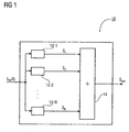
- Fig. 1 shows a block diagram of an apparatus for detecting a broadband information signal s HF (t) according to an embodiment of the present invention.
- the device 10 has a device 14 for combining the individual signals S n into a combined signal S ges , so that the spectrum of the combined signal S ges (f) essentially corresponds to the information signal spectrum S HF (f).
- the apparatus 10 for receiving the information signal s HF (t) may also include means for transforming the individual signals s n into the frequency domain.
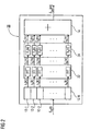
- FIG. 2 a further embodiment of an apparatus 20 for receiving the broadband information signal s HF (t).
- the information signal spectrum S HF (f) of the information signal s HF (t) can, for example, in Baseband are reconstructed.
- Fig. 3 shows a device 30 for detecting the information signal s HF (t) according to another embodiment of the present invention.
- the device 30 has two receivers 12-1 and 12-2 in the illustrated embodiment.
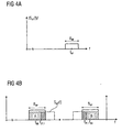
- Fig. 4a schematically shows the broadband information signal spectrum S HF (f) of the information signal s HF (t) with center frequency f HF and bandwidth B HF .
- Fig. 4b shows schematically the result of mixing the information signal s HF (t) with the local oscillator signal 32-1 with the frequency f LO , 1 , which in the case shown here is slightly below the center frequency f HF .
- the local oscillator frequency f LO, 1 is selected such that a lower part A of the spectrum S HF (f) comes to lie in the passband of the bandpass filter 33-1 with bandwidth B BP .
- the local oscillator frequency f LO, 1 is selected slightly below the center frequency f HF of the information signal.
- the information signal s HF (t) is compared with a local oscillator signal 32-2 different from the local oscillator signal 32-1 with a different local oscillator frequency f LO, 2 mixed.
- the upper part of the spectrum S HF (f) is to be in the band-pass filter passband having the bandwidth B BP , f LO, 2 is slightly increased from f LO, 1 .
- an analog-to-digital conversion of the intermediate frequency signals by means of the in Fig. 3 illustrated analog-to-digital converters 34-1 and 34-2.
- the Alias effect also creates bands in lower frequency ranges. This situation is schematic in Fig. 4c represented for the two reception branches.
- Reference numerals 50 and 50 'respectively denote the spectrum or the mirror spectrum of the intermediate frequency individual signals after bandpass filtering with the bandpass filter 33-1.
- the part indicated by the reference numeral 50 'corresponds to the mirror image of the lower part A of the information signal spectrum S HF (f) in the intermediate frequency range denoted by reference numeral 50.
- the area indicated by reference numeral 52 'corresponds to the mirror image of the upper portion B of the information signal spectrum S HF (f) indicated by reference numeral 52 in the intermediate frequency range.
- NCO numerically controlled oscillator
- the individual downmix signals are composed of the local oscillator signals and the NCO signals, since the information signal or a part of the information signal is mixed down both by the local oscillators and by the NCO's. Accordingly, in this case also the downmixing frequencies are composed of the local oscillator frequencies and the frequencies of the NCO signals (additive).
- the transfer function of such a low-pass filter is designated by the reference numeral 54.
- Parts of the overlapping regions of the lower and upper part spectra A, B can be removed by the point-symmetrical filter edges, so that their amplitudes in the overlap regions 1 and the original value complement each other in a later superimposition of the lower and upper part spectra A, B.
- This process is commonly referred to as zero padding.
- the length L FFT, n of the FFT can be configured.
- the choice of the FFT algorithm depends, inter alia, on the length L FFT, n of the FFT.
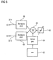
- a further oscillator 62 and a comb generator 64 a frequency comb with a line spectrum with a distance ⁇ f LO between individual spectral lines can be generated.
- the two generated signals are mixed in a mixer 66.
- Fig. 7a schematically shows the baseband spectrum of the processed discrete-frequency discrete signal S 1 (f). Further shows Fig. 7b the spectrum of the frequency-discrete processed single signal S 2 (f).
- the total spectrum S ges (f) resulting from the frequency-correct combination corresponds to the original information signal spectrum S HF (f) in the baseband range.
- the means 14 for combining so far processed separately processed individual signals in the frequency domain are superimposed or shifted and added that they join each other gapless.
- the respective overlapping area is considered, in which the preferably punctiform symmetrical flanks of the partial spectra overlap.
- the other data remain unchanged.
- the frequency offset ⁇ f LO between two adjacent downmixing signals resulting from the respective (anologic) local oscillator signal and / or the respective (digital) NCO signal, as described at the outset can correspond to an integer multiple of the bin spacing of the FFT.
- means 14 for combining is formed to the spectra of the transformed to the frequency range individual signals s n [k] to move in each case by their associated downmix frequencies in the frequency range up that differ by multiples of Binabstandes the FFT, so that the spectrum S ges (f) of the combined signal replicates the information signal spectrum S HF (f).
- the combination of the individual signals transformed into the frequency domain can be considerably simplified and made more efficient.
- IFFT Inverse Fast Fourier Transform
- the signal components of interest that have been transformed back into the discrete time domain can each be shifted into a desired frequency band, for example the baseband.
- a sample rate matching can be achieved. For example, a sampling rate conversion corresponding to the ratio of the length of the IFFT to the length L FFT of the FFTs for the individual individual signals could have taken place by a ratio L IFFT / L FFT in the time domain.
- FIG. 9 Another embodiment of a device for receiving a broadband information signal will now be described.
- apparatus 100 implemented the core of signal processing in the time domain.
- the present invention thus provides a method for receiving a broadband information signal having an information signal spectrum, comprising a step of generating a plurality of individual signals from the information signal with a plurality of receivers, each of the plurality of receivers comprising a mixer for down-converting the information signal with different downmixing signals. or local oscillator frequencies such that spectra of the individual signals each correspond to a different portion of the information signal spectrum, and a step of combining the individual signals into a combined signal such that the spectrum of the combined signal corresponds to the information signal spectrum.
- Embodiments of the present invention can be used in the field of broadband radio frequency receivers and signal recording devices. They make it possible to extract several channels with lower bandwidth from a broadband signal spectrum with little effort and to feed them to further processing. Furthermore, embodiments of the present invention facilitate the frequency parallelization of multiple recording devices to also detect signals whose bandwidth is above the bandwidth of the individual recording devices. Thus, for example, frequency hopping signals and other spread spectrum methods can be elucidated without equipment specially adapted to the application being required.
- the inventive scheme for receiving a broadband information signal can also be implemented in software.
- the implementation may be on a digital storage medium, in particular a floppy disk or a CD with electronically readable control signals, which may cooperate with a programmable computer system and / or microcontroller such that the corresponding method of receiving a broadband information signal is performed.
- the invention thus also consists in a computer program product with program code stored on a machine-readable carrier for carrying out the method according to the invention, when the computer program product runs on a computer and / or microcontroller.
- the invention can thus be realized as a computer program with a program code for carrying out a method for simulating a signal composed of a plurality of individual signals when the computer program runs on a computer and / or microcontroller.
Landscapes
- Engineering & Computer Science (AREA)
- Computer Networks & Wireless Communication (AREA)
- Signal Processing (AREA)
- Superheterodyne Receivers (AREA)
- Digital Transmission Methods That Use Modulated Carrier Waves (AREA)
- Radar Systems Or Details Thereof (AREA)
- Monitoring And Testing Of Transmission In General (AREA)
Claims (16)
- Dispositif (10; 20; 30; 100) pour recevoir un signal d'information (sHF(t)) avec un spectre de signal d'information (SHF(f)), aux caractéristiques suivantes:une pluralité de récepteurs (12-n) destinés à générer, chacun, un signal individuel (sn[k]) à partir du signal d'information, chacun de la pluralité de récepteurs présentant un mélangeur destiné à mélanger vers le bas le signal d'information avec un signal de mélange descendant respectif, et les fréquences de mélange descendant des signaux de mélange descendant différant l'une de l'autre, de sorte que les spectres des signaux individuels (Sn(f)) correspondent chaque fois à une partie différente du spectre de signal d'information;un moyen (22) destiné à transformer les signaux individuels (sn[k]) au domaine fréquentiel, lequel est réalisé pour transformer des segments des signaux individuels (sn[k]) chaque fois à l'aide d'une transformation de Fourier rapide (FFT) d'un domaine temporel en un domaine fréquentiel,un décalage de fréquence (ΔfLO) entre deux signaux de mélange descendant adjacents correspondant à un multiple de nombre entier d'une distance de bin de la transformation de Fourier rapide; etun moyen (14) destiné à combiner les signaux individuels (sn[k]), pour obtenir un signal combiné qui est conçu pour déplacer les plages de fréquences des signaux individuels (sn[k]) selon les décalages de fréquence associés aux signaux individuels (sn[k]) autour des différentes fréquences de mélange descendant, de sorte que le spectre (Stot(f)) du signal combiné reproduise le spectre du signal d'information (SHF(f)).
- Dispositif selon la revendication 1, dans lequel un mélangeur comporte un oscillateur local et un signal de mélange descendant est un signal d'oscillateur local.
- Dispositif selon la revendication 2, présentant par ailleurs un moyen destiné à générer les signaux d'oscillateur local (32-n) chaque fois en mélangeant un peigne de fréquence avec un signal d'oscillateur.
- Dispositif selon la revendication 1, dans lequel un mélangeur comporte un oscillateur local et/ou un mélangeur numérique, et un signal de mélange descendant comporte un signal d'oscillateur local et/ou un signal numérique.
- Dispositif selon l'une des revendications précédentes, dans lequel les fréquences de mélange descendant (fLO,n) sont choisies de manière à convertir différentes parties du signal d'information (sHF(t)) avec différentes parts spectrales du spectre de signal d'information (SHF(f)) chaque fois en des signaux de fréquence intermédiaire dans une plage de fréquences intermédiaires.
- Dispositif selon l'une des revendications précédentes, dans lequel la pluralité de récepteurs (12-n) présentent, chacun, un filtre passe-bande (33-n), et les filtres passe-bande (33-n) présentent une même largeur de bande passe-bande (BBP), pour sortir par filtration les parties différentes respectives du spectre de signal d'information (SHF(f)) des signaux de fréquence intermédiaire.
- Dispositif selon la revendication 6, dans lequel la pluralité de récepteurs (12-n) comportent, chacun, un convertisseur AN (34-n), pour convertir d'analogique à numérique les signaux à fréquence intermédiaire à fréquence de balayage supérieure ou égale à la largeur de bande passe-bande (BBP).
- Dispositif selon l'une des revendications précédentes, dans lequel la pluralité de récepteurs (12-n) présentent, chacun, un moyen (35-n) destiné au mélange numérique et un oscillateur contrôlé numériquement (36-n), pour pouvoir déplacer les signaux à fréquence intermédiaire convertis d'analogique à numérique d'une fréquence réglable de l'oscillateur contrôlé numériquement.
- Dispositif selon l'une des revendications 6 à 8, dans lequel la pluralité de récepteurs (12-n) présentent, chacun, un filtre passe-bas numérique (37-n) à flancs de filtre symétriques par rapport à un point et à largeur de bande de filtre (BTP) dans une plage de 0,6 BBP < BTP < BBP.
- Dispositif selon la revendication 1, dans lequel le moyen (22) pour la transformation respective fonctionne par segment de signal, pour transformer les segments des signaux individuels sous forme remplie de zéros.
- Dispositif selon la revendication 1, dans lequel une largeur de bande de la FFT est de l'ordre de grandeur de deux fois la largeur de bande du signal individuel (sn[k]).
- Dispositif selon l'une des revendications précédentes, dans lequel le dispositif comporte par ailleurs un moyen (24) de pondération spectrale à valeurs complexes des signaux individuels transformés au domaine fréquentiel.
- Dispositif selon la revendication 12, dans lequel le moyen (24) de traitement est réalisé pour multiplier les signaux individuels transformés au domaine fréquentiel chaque fois par une fonction de transmission inverse (Hn[m]) du canal de signal présent, la fonction de transmission inverse étant à valeurs complexes.
- Dispositif selon la revendication 1, dans lequel le moyen (14) pour combiner est par ailleurs réalisé pour additionner les signaux individuels (sn[k]) déplacés selon leurs fréquences de mélange vers le bas (fLO,n), pour obtenir le signal combiné et pour tenir compte de zones de recouvrement spectral entre les signaux individuels déplacés (sn[k]), de sorte que le spectre (Stot(f)) du signal combiné corresponde au spectre du signal d'information (SHF(f)).
- Procédé pour recevoir un signal d'information (SHF(t)) avec un spectre de signal d'information (SHF(f)), aux étapes suivantes consistant à:générer une pluralité de signaux individuels (sn[k]) à partir du signal d'information au moyen d'une pluralité de récepteurs (12-n), chacun de la pluralité de récepteurs présentant un mélangeur (31-n) destiné à mélanger vers le bas le signal d'information avec des signaux de mélange vers le bas (32-n) à fréquences de mélange vers le bas (fLO,n) différentes, de sorte que les spectres des signaux individuels (Sn(f)) correspondent, chacun, à une partie différente du spectre de signal d'information; ettransformer les signaux individuels (sn[k] au domaine fréquentiel, qui est conçue de manière à transformer les segments des signaux individuels (sn[k]) chaque fois au moyen d'une transformation de Fourier rapide (FFT) d'un domaine temporel à un domaine fréquentiel,un décalage de fréquence (ΔfL0) entre deux signaux de mélange vers le bas adjacents (32-n) correspondant à un multiple de nombre entier d'une distance de bin de la transformation de Fourier rapide; etcombiner la pluralité de signaux individuels (sn[k)), pour obtenir un signal combiné par le déplacement des plages de fréquences des signaux individuels (sn[k]) selon les décalages de fréquence associés aux signaux individuels (sn[k]) autour des différentes fréquences de mélange descendant (fLO,n), de sorte que le spectre (Stot(f)) du signal combiné corresponde au spectre du signal d'information (SHF(f)).
- Programme d'ordinateur pour réaliser les étapes du procédé selon la revendication 15 lorsque le programme d'ordinateur est exécuté sur un ordinateur ou un microcontrôleur.
Applications Claiming Priority (2)
| Application Number | Priority Date | Filing Date | Title |
|---|---|---|---|
| DE102007044469A DE102007044469A1 (de) | 2007-09-18 | 2007-09-18 | Vorrichtung und Verfahren zum Empfangen eines Informationssignals mit einem Informationssignalspektrum |
| PCT/EP2008/007834 WO2009036981A1 (fr) | 2007-09-18 | 2008-09-18 | Dispositif et procédé pour recevoir un signal d'information présentant un spectre de signal d'information |
Publications (3)
| Publication Number | Publication Date |
|---|---|
| EP2191579A1 EP2191579A1 (fr) | 2010-06-02 |
| EP2191579B1 true EP2191579B1 (fr) | 2011-03-23 |
| EP2191579B2 EP2191579B2 (fr) | 2023-01-11 |
Family
ID=40040076
Family Applications (1)
| Application Number | Title | Priority Date | Filing Date |
|---|---|---|---|
| EP08802354.4A Active EP2191579B2 (fr) | 2007-09-18 | 2008-09-18 | Dispositif et procédé pour recevoir un signal d'information présentant un spectre de signal d'information |
Country Status (4)
| Country | Link |
|---|---|
| EP (1) | EP2191579B2 (fr) |
| AT (1) | ATE503305T1 (fr) |
| DE (2) | DE102007044469A1 (fr) |
| WO (1) | WO2009036981A1 (fr) |
Cited By (1)
| Publication number | Priority date | Publication date | Assignee | Title |
|---|---|---|---|---|
| DE102015219739A1 (de) | 2015-10-12 | 2017-04-13 | Innovationszentrum für Telekommunikationstechnik GmbH IZT | Empfänger |
Families Citing this family (2)
| Publication number | Priority date | Publication date | Assignee | Title |
|---|---|---|---|---|
| EP2403145A1 (fr) * | 2010-07-01 | 2012-01-04 | Fraunhofer-Gesellschaft zur Förderung der angewandten Forschung e.V. | Récepteur et procédé de traitement de signal |
| US8805297B2 (en) * | 2012-10-16 | 2014-08-12 | Raytheon Company | Band stitching electronic circuits and techniques |
Family Cites Families (11)
| Publication number | Priority date | Publication date | Assignee | Title |
|---|---|---|---|---|
| GB2180112B (en) † | 1985-08-02 | 1990-01-31 | Nat Res Dev | Transparent tone-in band transmitters receivers and systems |
| US4800341A (en) * | 1987-11-02 | 1989-01-24 | Eaton Corporation | Fast switching frequency synthesizer |
| DE4330425A1 (de) † | 1992-09-08 | 1994-03-10 | Aerometrics Inc | Verfahren und Anordnung zur Bestimmung der Frequenz eines zeitvariablen elektronischen Signals |
| US5293114A (en) * | 1992-12-24 | 1994-03-08 | The United States Of America As Represented By The Secretary Of The Air Force | Frequency measurement receiver with means to resolve an ambiguity in multiple frequency estimation |
| US5412690A (en) * | 1993-03-08 | 1995-05-02 | Motorola, Inc. | Method and apparatus for receiving electromagnetic radiation within a frequency band |
| US5535240A (en) * | 1993-10-29 | 1996-07-09 | Airnet Communications Corporation | Transceiver apparatus employing wideband FFT channelizer and inverse FFT combiner for multichannel communication network |
| US5870436A (en) * | 1997-01-02 | 1999-02-09 | Raytheon Company | Uniform discrete fourier transform filter parameter encoder |
| DE10016483A1 (de) * | 2000-04-01 | 2001-10-18 | Plath Naut Elektron Tech | Vielkanalpeiler |
| US7512197B2 (en) † | 2005-02-07 | 2009-03-31 | Harris Corporation | System and method for removing interfering narrowband signals from wide bandwidth receive signal |
| US7944995B2 (en) * | 2005-11-14 | 2011-05-17 | Telefonaktiebolaget Lm Ericsson (Publ) | Variable bandwidth receiver |
| US20070171993A1 (en) * | 2006-01-23 | 2007-07-26 | Faraday Technology Corp. | Adaptive overlap and add circuit and method for zero-padding OFDM system |
-
2007
- 2007-09-18 DE DE102007044469A patent/DE102007044469A1/de not_active Withdrawn
-
2008
- 2008-09-18 AT AT08802354T patent/ATE503305T1/de active
- 2008-09-18 DE DE502008002965T patent/DE502008002965D1/de active Active
- 2008-09-18 WO PCT/EP2008/007834 patent/WO2009036981A1/fr not_active Ceased
- 2008-09-18 EP EP08802354.4A patent/EP2191579B2/fr active Active
Cited By (3)
| Publication number | Priority date | Publication date | Assignee | Title |
|---|---|---|---|---|
| DE102015219739A1 (de) | 2015-10-12 | 2017-04-13 | Innovationszentrum für Telekommunikationstechnik GmbH IZT | Empfänger |
| WO2017063931A1 (fr) | 2015-10-12 | 2017-04-20 | Innovationszentrum für Telekommunikationstechnik GmbH IZT | Récepteur comportant au moins deux voies de réception pour numérisation de sous-bandes filtrées |
| US10256857B2 (en) | 2015-10-12 | 2019-04-09 | Innovationszentrum fur Telekommunikationstechnik GmbH IZT | Receiver |
Also Published As
| Publication number | Publication date |
|---|---|
| DE102007044469A1 (de) | 2009-04-09 |
| ATE503305T1 (de) | 2011-04-15 |
| EP2191579A1 (fr) | 2010-06-02 |
| DE502008002965D1 (de) | 2011-05-05 |
| EP2191579B2 (fr) | 2023-01-11 |
| WO2009036981A1 (fr) | 2009-03-26 |
Similar Documents
| Publication | Publication Date | Title |
|---|---|---|
| DE69114733T2 (de) | Verfahren zur Datenverbreitung mit Zeit-Frequenzverschachtelung mit Verwendung von Bezugsfrequenzsignalen. | |
| DE102014218909B4 (de) | Kommunikationseinheit und Verfahren zum Bestimmen und/oder Kompensieren von frequenzabhängiger Quadraturfehlanpassung | |
| DE60131407T2 (de) | Empfängerschaltung | |
| DE60225467T2 (de) | Digitaler multiratensender/-empfänger | |
| EP3459173B1 (fr) | Procédé et dispositif d'envoi ou de réception d'au moins un signal à haute fréquence avec traitement de signal en bande de base parallele et sous-échantillonné | |
| EP0740869B1 (fr) | Procede de correction de frequence numerique pour des processus de transmission a porteuses multiples | |
| DE69309022T2 (de) | Maximalwahrscheinlichtkeits-Datendetektor | |
| DE60315960T2 (de) | Verfahren und vorrichtung zur analog-/digital-umsetzung | |
| EP2191579B1 (fr) | Dispositif et procédé pour recevoir un signal d'information présentant un spectre de signal d'information | |
| EP1825646B1 (fr) | Conversion d'un signal de début complexe en un signal de fin complexe d'une fréquence plus haute ou plus basse | |
| DE102011075893B4 (de) | Vorrichtung und Verfahren zur adaptiven Unterdrückung von In-Band-Störsignalen bei Funk-Empfängern | |
| DE112009004422B4 (de) | Empfänger | |
| DE69107679T2 (de) | Quadraturdemodulator. | |
| DE4332735C2 (de) | Verfahren zum digitalen Erzeugen eines komplexen Basisbandsignals | |
| EP1815589B1 (fr) | Melangeur pour melanger un signal et procede pour melanger un signal | |
| DE10248507A1 (de) | Verfahren und Vorrichtung zur Fehlerkorrektur von Multiplex-Signalen | |
| DE102013103452B4 (de) | Abtastempfänger mit inhärenter Mischerfunktionalität im diskreten Zeitbereich - Mischer-Filter-Schaltung, Empfängersystem und Verfahren zum Filtern und Mischen | |
| WO2004036781A1 (fr) | Dispositif et procede permettant de suivre un moment fixe d'echantillonnage dans des recepteurs radio | |
| WO2006063766A1 (fr) | Convertisseur de frequence pour la conversion spectrale d'un signal initial et procede pour la conversion spectrale d'un signal initial | |
| WO2001060005A1 (fr) | Procede de determination de la puissance des porteurs restante pour un signal multiporteur a modulation d'amplitude en quadrature, en mode 8k, selon la norme dvb-t | |
| DE10152628A1 (de) | Adaptives Kanalfilter für Mobilfunkempfänger und Verfahren zur adaptiven Kanalfilterung | |
| DE10129317A1 (de) | Verfahren zum Anpassen von Filtereckfrequenzen beim Übertragen von diskreten Mehrfachtonsymbolen | |
| DE10360470B4 (de) | Verfahren und Vorrichtung zum Demodulieren eines Empfangssignals | |
| DE102008014754A1 (de) | Kombinierter Mischer und Mehrphasendezimator | |
| DE10361037A1 (de) | Verfahren und Vorrichtung zur Demodulation eines phasenmodulierten Signals |
Legal Events
| Date | Code | Title | Description |
|---|---|---|---|
| PUAI | Public reference made under article 153(3) epc to a published international application that has entered the european phase |
Free format text: ORIGINAL CODE: 0009012 |
|
| 17P | Request for examination filed |
Effective date: 20100303 |
|
| AK | Designated contracting states |
Kind code of ref document: A1 Designated state(s): AT BE BG CH CY CZ DE DK EE ES FI FR GB GR HR HU IE IS IT LI LT LU LV MC MT NL NO PL PT RO SE SI SK TR |
|
| AX | Request for extension of the european patent |
Extension state: AL BA MK RS |
|
| RIN1 | Information on inventor provided before grant (corrected) |
Inventor name: PERTHOLD, RAINER |
|
| GRAP | Despatch of communication of intention to grant a patent |
Free format text: ORIGINAL CODE: EPIDOSNIGR1 |
|
| DAX | Request for extension of the european patent (deleted) | ||
| GRAS | Grant fee paid |
Free format text: ORIGINAL CODE: EPIDOSNIGR3 |
|
| GRAA | (expected) grant |
Free format text: ORIGINAL CODE: 0009210 |
|
| AK | Designated contracting states |
Kind code of ref document: B1 Designated state(s): AT BE BG CH CY CZ DE DK EE ES FI FR GB GR HR HU IE IS IT LI LT LU LV MC MT NL NO PL PT RO SE SI SK TR |
|
| REG | Reference to a national code |
Ref country code: GB Ref legal event code: FG4D Free format text: NOT ENGLISH |
|
| REG | Reference to a national code |
Ref country code: CH Ref legal event code: EP |
|
| REG | Reference to a national code |
Ref country code: IE Ref legal event code: FG4D |
|
| REF | Corresponds to: |
Ref document number: 502008002965 Country of ref document: DE Date of ref document: 20110505 Kind code of ref document: P |
|
| REG | Reference to a national code |
Ref country code: DE Ref legal event code: R096 Ref document number: 502008002965 Country of ref document: DE Effective date: 20110505 |
|
| REG | Reference to a national code |
Ref country code: NL Ref legal event code: VDEP Effective date: 20110323 |
|
| PG25 | Lapsed in a contracting state [announced via postgrant information from national office to epo] |
Ref country code: SE Free format text: LAPSE BECAUSE OF FAILURE TO SUBMIT A TRANSLATION OF THE DESCRIPTION OR TO PAY THE FEE WITHIN THE PRESCRIBED TIME-LIMIT Effective date: 20110323 Ref country code: LT Free format text: LAPSE BECAUSE OF FAILURE TO SUBMIT A TRANSLATION OF THE DESCRIPTION OR TO PAY THE FEE WITHIN THE PRESCRIBED TIME-LIMIT Effective date: 20110323 Ref country code: HR Free format text: LAPSE BECAUSE OF FAILURE TO SUBMIT A TRANSLATION OF THE DESCRIPTION OR TO PAY THE FEE WITHIN THE PRESCRIBED TIME-LIMIT Effective date: 20110323 Ref country code: LV Free format text: LAPSE BECAUSE OF FAILURE TO SUBMIT A TRANSLATION OF THE DESCRIPTION OR TO PAY THE FEE WITHIN THE PRESCRIBED TIME-LIMIT Effective date: 20110323 Ref country code: GR Free format text: LAPSE BECAUSE OF FAILURE TO SUBMIT A TRANSLATION OF THE DESCRIPTION OR TO PAY THE FEE WITHIN THE PRESCRIBED TIME-LIMIT Effective date: 20110624 |
|
| LTIE | Lt: invalidation of european patent or patent extension |
Effective date: 20110323 |
|
| PG25 | Lapsed in a contracting state [announced via postgrant information from national office to epo] |
Ref country code: CY Free format text: LAPSE BECAUSE OF FAILURE TO SUBMIT A TRANSLATION OF THE DESCRIPTION OR TO PAY THE FEE WITHIN THE PRESCRIBED TIME-LIMIT Effective date: 20110323 Ref country code: BG Free format text: LAPSE BECAUSE OF FAILURE TO SUBMIT A TRANSLATION OF THE DESCRIPTION OR TO PAY THE FEE WITHIN THE PRESCRIBED TIME-LIMIT Effective date: 20110623 Ref country code: FI Free format text: LAPSE BECAUSE OF FAILURE TO SUBMIT A TRANSLATION OF THE DESCRIPTION OR TO PAY THE FEE WITHIN THE PRESCRIBED TIME-LIMIT Effective date: 20110323 Ref country code: NO Free format text: LAPSE BECAUSE OF FAILURE TO SUBMIT A TRANSLATION OF THE DESCRIPTION OR TO PAY THE FEE WITHIN THE PRESCRIBED TIME-LIMIT Effective date: 20110623 Ref country code: SI Free format text: LAPSE BECAUSE OF FAILURE TO SUBMIT A TRANSLATION OF THE DESCRIPTION OR TO PAY THE FEE WITHIN THE PRESCRIBED TIME-LIMIT Effective date: 20110323 |
|
| REG | Reference to a national code |
Ref country code: IE Ref legal event code: FD4D |
|
| PG25 | Lapsed in a contracting state [announced via postgrant information from national office to epo] |
Ref country code: EE Free format text: LAPSE BECAUSE OF FAILURE TO SUBMIT A TRANSLATION OF THE DESCRIPTION OR TO PAY THE FEE WITHIN THE PRESCRIBED TIME-LIMIT Effective date: 20110323 Ref country code: PT Free format text: LAPSE BECAUSE OF FAILURE TO SUBMIT A TRANSLATION OF THE DESCRIPTION OR TO PAY THE FEE WITHIN THE PRESCRIBED TIME-LIMIT Effective date: 20110725 |
|
| PLBI | Opposition filed |
Free format text: ORIGINAL CODE: 0009260 |
|
| PG25 | Lapsed in a contracting state [announced via postgrant information from national office to epo] |
Ref country code: ES Free format text: LAPSE BECAUSE OF FAILURE TO SUBMIT A TRANSLATION OF THE DESCRIPTION OR TO PAY THE FEE WITHIN THE PRESCRIBED TIME-LIMIT Effective date: 20110704 Ref country code: IS Free format text: LAPSE BECAUSE OF FAILURE TO SUBMIT A TRANSLATION OF THE DESCRIPTION OR TO PAY THE FEE WITHIN THE PRESCRIBED TIME-LIMIT Effective date: 20110723 Ref country code: CZ Free format text: LAPSE BECAUSE OF FAILURE TO SUBMIT A TRANSLATION OF THE DESCRIPTION OR TO PAY THE FEE WITHIN THE PRESCRIBED TIME-LIMIT Effective date: 20110323 Ref country code: RO Free format text: LAPSE BECAUSE OF FAILURE TO SUBMIT A TRANSLATION OF THE DESCRIPTION OR TO PAY THE FEE WITHIN THE PRESCRIBED TIME-LIMIT Effective date: 20110323 Ref country code: SK Free format text: LAPSE BECAUSE OF FAILURE TO SUBMIT A TRANSLATION OF THE DESCRIPTION OR TO PAY THE FEE WITHIN THE PRESCRIBED TIME-LIMIT Effective date: 20110323 |
|
| 26 | Opposition filed |
Opponent name: KOERFER, THOMAS Effective date: 20111118 |
|
| PG25 | Lapsed in a contracting state [announced via postgrant information from national office to epo] |
Ref country code: NL Free format text: LAPSE BECAUSE OF FAILURE TO SUBMIT A TRANSLATION OF THE DESCRIPTION OR TO PAY THE FEE WITHIN THE PRESCRIBED TIME-LIMIT Effective date: 20110323 |
|
| PLAX | Notice of opposition and request to file observation + time limit sent |
Free format text: ORIGINAL CODE: EPIDOSNOBS2 |
|
| PG25 | Lapsed in a contracting state [announced via postgrant information from national office to epo] |
Ref country code: IE Free format text: LAPSE BECAUSE OF FAILURE TO SUBMIT A TRANSLATION OF THE DESCRIPTION OR TO PAY THE FEE WITHIN THE PRESCRIBED TIME-LIMIT Effective date: 20110323 |
|
| REG | Reference to a national code |
Ref country code: DE Ref legal event code: R026 Ref document number: 502008002965 Country of ref document: DE Effective date: 20111118 |
|
| PG25 | Lapsed in a contracting state [announced via postgrant information from national office to epo] |
Ref country code: PL Free format text: LAPSE BECAUSE OF FAILURE TO SUBMIT A TRANSLATION OF THE DESCRIPTION OR TO PAY THE FEE WITHIN THE PRESCRIBED TIME-LIMIT Effective date: 20110323 |
|
| BERE | Be: lapsed |
Owner name: INNOVATIONSZENTRUM FUR TELEKOMMUNIKATIONSTECHNIK Effective date: 20110930 |
|
| PLBB | Reply of patent proprietor to notice(s) of opposition received |
Free format text: ORIGINAL CODE: EPIDOSNOBS3 |
|
| PG25 | Lapsed in a contracting state [announced via postgrant information from national office to epo] |
Ref country code: MC Free format text: LAPSE BECAUSE OF NON-PAYMENT OF DUE FEES Effective date: 20110930 |
|
| PG25 | Lapsed in a contracting state [announced via postgrant information from national office to epo] |
Ref country code: IT Free format text: LAPSE BECAUSE OF FAILURE TO SUBMIT A TRANSLATION OF THE DESCRIPTION OR TO PAY THE FEE WITHIN THE PRESCRIBED TIME-LIMIT Effective date: 20110323 |
|
| PG25 | Lapsed in a contracting state [announced via postgrant information from national office to epo] |
Ref country code: BE Free format text: LAPSE BECAUSE OF NON-PAYMENT OF DUE FEES Effective date: 20110930 |
|
| PG25 | Lapsed in a contracting state [announced via postgrant information from national office to epo] |
Ref country code: MT Free format text: LAPSE BECAUSE OF FAILURE TO SUBMIT A TRANSLATION OF THE DESCRIPTION OR TO PAY THE FEE WITHIN THE PRESCRIBED TIME-LIMIT Effective date: 20110323 |
|
| REG | Reference to a national code |
Ref country code: CH Ref legal event code: PL |
|
| PG25 | Lapsed in a contracting state [announced via postgrant information from national office to epo] |
Ref country code: LU Free format text: LAPSE BECAUSE OF NON-PAYMENT OF DUE FEES Effective date: 20110918 |
|
| PG25 | Lapsed in a contracting state [announced via postgrant information from national office to epo] |
Ref country code: LI Free format text: LAPSE BECAUSE OF NON-PAYMENT OF DUE FEES Effective date: 20120930 Ref country code: CH Free format text: LAPSE BECAUSE OF NON-PAYMENT OF DUE FEES Effective date: 20120930 |
|
| PG25 | Lapsed in a contracting state [announced via postgrant information from national office to epo] |
Ref country code: TR Free format text: LAPSE BECAUSE OF FAILURE TO SUBMIT A TRANSLATION OF THE DESCRIPTION OR TO PAY THE FEE WITHIN THE PRESCRIBED TIME-LIMIT Effective date: 20110323 |
|
| PG25 | Lapsed in a contracting state [announced via postgrant information from national office to epo] |
Ref country code: HU Free format text: LAPSE BECAUSE OF FAILURE TO SUBMIT A TRANSLATION OF THE DESCRIPTION OR TO PAY THE FEE WITHIN THE PRESCRIBED TIME-LIMIT Effective date: 20110323 |
|
| REG | Reference to a national code |
Ref country code: AT Ref legal event code: MM01 Ref document number: 503305 Country of ref document: AT Kind code of ref document: T Effective date: 20130918 |
|
| PLCK | Communication despatched that opposition was rejected |
Free format text: ORIGINAL CODE: EPIDOSNREJ1 |
|
| PG25 | Lapsed in a contracting state [announced via postgrant information from national office to epo] |
Ref country code: AT Free format text: LAPSE BECAUSE OF NON-PAYMENT OF DUE FEES Effective date: 20130918 |
|
| APAH | Appeal reference modified |
Free format text: ORIGINAL CODE: EPIDOSCREFNO |
|
| APBM | Appeal reference recorded |
Free format text: ORIGINAL CODE: EPIDOSNREFNO |
|
| APBP | Date of receipt of notice of appeal recorded |
Free format text: ORIGINAL CODE: EPIDOSNNOA2O |
|
| APBQ | Date of receipt of statement of grounds of appeal recorded |
Free format text: ORIGINAL CODE: EPIDOSNNOA3O |
|
| REG | Reference to a national code |
Ref country code: FR Ref legal event code: PLFP Year of fee payment: 9 |
|
| REG | Reference to a national code |
Ref country code: FR Ref legal event code: PLFP Year of fee payment: 10 |
|
| REG | Reference to a national code |
Ref country code: FR Ref legal event code: PLFP Year of fee payment: 11 |
|
| APBU | Appeal procedure closed |
Free format text: ORIGINAL CODE: EPIDOSNNOA9O |
|
| PLAH | Information related to despatch of examination report in opposition + time limit modified |
Free format text: ORIGINAL CODE: EPIDOSCORE2 |
|
| PLAY | Examination report in opposition despatched + time limit |
Free format text: ORIGINAL CODE: EPIDOSNORE2 |
|
| PLBC | Reply to examination report in opposition received |
Free format text: ORIGINAL CODE: EPIDOSNORE3 |
|
| PLAY | Examination report in opposition despatched + time limit |
Free format text: ORIGINAL CODE: EPIDOSNORE2 |
|
| PLBC | Reply to examination report in opposition received |
Free format text: ORIGINAL CODE: EPIDOSNORE3 |
|
| PLAP | Information related to despatch of examination report in opposition + time limit deleted |
Free format text: ORIGINAL CODE: EPIDOSDORE2 |
|
| PLAT | Information related to reply to examination report in opposition deleted |
Free format text: ORIGINAL CODE: EPIDOSDORE3 |
|
| PLAY | Examination report in opposition despatched + time limit |
Free format text: ORIGINAL CODE: EPIDOSNORE2 |
|
| PLBC | Reply to examination report in opposition received |
Free format text: ORIGINAL CODE: EPIDOSNORE3 |
|
| PLAP | Information related to despatch of examination report in opposition + time limit deleted |
Free format text: ORIGINAL CODE: EPIDOSDORE2 |
|
| PLAT | Information related to reply to examination report in opposition deleted |
Free format text: ORIGINAL CODE: EPIDOSDORE3 |
|
| PLAY | Examination report in opposition despatched + time limit |
Free format text: ORIGINAL CODE: EPIDOSNORE2 |
|
| PLAH | Information related to despatch of examination report in opposition + time limit modified |
Free format text: ORIGINAL CODE: EPIDOSCORE2 |
|
| PLBC | Reply to examination report in opposition received |
Free format text: ORIGINAL CODE: EPIDOSNORE3 |
|
| PUAH | Patent maintained in amended form |
Free format text: ORIGINAL CODE: 0009272 |
|
| STAA | Information on the status of an ep patent application or granted ep patent |
Free format text: STATUS: PATENT MAINTAINED AS AMENDED |
|
| 27A | Patent maintained in amended form |
Effective date: 20230111 |
|
| AK | Designated contracting states |
Kind code of ref document: B2 Designated state(s): AT BE BG CH CY CZ DE DK EE ES FI FR GB GR HR HU IE IS IT LI LT LU LV MC MT NL NO PL PT RO SE SI SK TR |
|
| REG | Reference to a national code |
Ref country code: DE Ref legal event code: R102 Ref document number: 502008002965 Country of ref document: DE |
|
| PGFP | Annual fee paid to national office [announced via postgrant information from national office to epo] |
Ref country code: DE Payment date: 20250724 Year of fee payment: 18 |
|
| PGFP | Annual fee paid to national office [announced via postgrant information from national office to epo] |
Ref country code: GB Payment date: 20250927 Year of fee payment: 18 |
|
| PGFP | Annual fee paid to national office [announced via postgrant information from national office to epo] |
Ref country code: FR Payment date: 20250926 Year of fee payment: 18 |