EP2191780A1 - Aufnahmeteil für die Aufnahme einer Stange zur Kopplung der Stange mit einem Knochenverankerungselement und eine Knochenverankerungsvorrichtung mit einem derartigen Aufnahmeteil - Google Patents
Aufnahmeteil für die Aufnahme einer Stange zur Kopplung der Stange mit einem Knochenverankerungselement und eine Knochenverankerungsvorrichtung mit einem derartigen Aufnahmeteil Download PDFInfo
- Publication number
- EP2191780A1 EP2191780A1 EP08020737A EP08020737A EP2191780A1 EP 2191780 A1 EP2191780 A1 EP 2191780A1 EP 08020737 A EP08020737 A EP 08020737A EP 08020737 A EP08020737 A EP 08020737A EP 2191780 A1 EP2191780 A1 EP 2191780A1
- Authority
- EP
- European Patent Office
- Prior art keywords
- head
- rod
- receiving part
- receiving
- locking ring
- Prior art date
- Legal status (The legal status is an assumption and is not a legal conclusion. Google has not performed a legal analysis and makes no representation as to the accuracy of the status listed.)
- Granted
Links
Images



Classifications
-
- A—HUMAN NECESSITIES
- A61—MEDICAL OR VETERINARY SCIENCE; HYGIENE
- A61B—DIAGNOSIS; SURGERY; IDENTIFICATION
- A61B17/00—Surgical instruments, devices or methods
- A61B17/56—Surgical instruments or methods for treatment of bones or joints; Devices specially adapted therefor
- A61B17/58—Surgical instruments or methods for treatment of bones or joints; Devices specially adapted therefor for osteosynthesis, e.g. bone plates, screws or setting implements
-
- A—HUMAN NECESSITIES
- A61—MEDICAL OR VETERINARY SCIENCE; HYGIENE
- A61B—DIAGNOSIS; SURGERY; IDENTIFICATION
- A61B17/00—Surgical instruments, devices or methods
- A61B17/56—Surgical instruments or methods for treatment of bones or joints; Devices specially adapted therefor
- A61B17/58—Surgical instruments or methods for treatment of bones or joints; Devices specially adapted therefor for osteosynthesis, e.g. bone plates, screws or setting implements
- A61B17/68—Internal fixation devices, including fasteners and spinal fixators, even if a part thereof projects from the skin
- A61B17/70—Spinal positioners or stabilisers, e.g. stabilisers comprising fluid filler in an implant
- A61B17/7001—Screws or hooks combined with longitudinal elements which do not contact vertebrae
- A61B17/7032—Screws or hooks with U-shaped head or back through which longitudinal rods pass
-
- A—HUMAN NECESSITIES
- A61—MEDICAL OR VETERINARY SCIENCE; HYGIENE
- A61B—DIAGNOSIS; SURGERY; IDENTIFICATION
- A61B17/00—Surgical instruments, devices or methods
- A61B17/56—Surgical instruments or methods for treatment of bones or joints; Devices specially adapted therefor
- A61B17/58—Surgical instruments or methods for treatment of bones or joints; Devices specially adapted therefor for osteosynthesis, e.g. bone plates, screws or setting implements
- A61B17/68—Internal fixation devices, including fasteners and spinal fixators, even if a part thereof projects from the skin
- A61B17/685—Elements to be fitted on the end of screws or wires, e.g. protective caps
-
- A—HUMAN NECESSITIES
- A61—MEDICAL OR VETERINARY SCIENCE; HYGIENE
- A61B—DIAGNOSIS; SURGERY; IDENTIFICATION
- A61B17/00—Surgical instruments, devices or methods
- A61B17/56—Surgical instruments or methods for treatment of bones or joints; Devices specially adapted therefor
- A61B17/58—Surgical instruments or methods for treatment of bones or joints; Devices specially adapted therefor for osteosynthesis, e.g. bone plates, screws or setting implements
- A61B17/68—Internal fixation devices, including fasteners and spinal fixators, even if a part thereof projects from the skin
-
- A—HUMAN NECESSITIES
- A61—MEDICAL OR VETERINARY SCIENCE; HYGIENE
- A61B—DIAGNOSIS; SURGERY; IDENTIFICATION
- A61B17/00—Surgical instruments, devices or methods
- A61B17/56—Surgical instruments or methods for treatment of bones or joints; Devices specially adapted therefor
- A61B17/58—Surgical instruments or methods for treatment of bones or joints; Devices specially adapted therefor for osteosynthesis, e.g. bone plates, screws or setting implements
- A61B17/68—Internal fixation devices, including fasteners and spinal fixators, even if a part thereof projects from the skin
- A61B17/70—Spinal positioners or stabilisers, e.g. stabilisers comprising fluid filler in an implant
- A61B17/7001—Screws or hooks combined with longitudinal elements which do not contact vertebrae
- A61B17/7035—Screws or hooks, wherein a rod-clamping part and a bone-anchoring part can pivot relative to each other
-
- A—HUMAN NECESSITIES
- A61—MEDICAL OR VETERINARY SCIENCE; HYGIENE
- A61B—DIAGNOSIS; SURGERY; IDENTIFICATION
- A61B17/00—Surgical instruments, devices or methods
- A61B17/56—Surgical instruments or methods for treatment of bones or joints; Devices specially adapted therefor
- A61B17/58—Surgical instruments or methods for treatment of bones or joints; Devices specially adapted therefor for osteosynthesis, e.g. bone plates, screws or setting implements
- A61B17/68—Internal fixation devices, including fasteners and spinal fixators, even if a part thereof projects from the skin
- A61B17/70—Spinal positioners or stabilisers, e.g. stabilisers comprising fluid filler in an implant
- A61B17/7001—Screws or hooks combined with longitudinal elements which do not contact vertebrae
- A61B17/7035—Screws or hooks, wherein a rod-clamping part and a bone-anchoring part can pivot relative to each other
- A61B17/7037—Screws or hooks, wherein a rod-clamping part and a bone-anchoring part can pivot relative to each other wherein pivoting is blocked when the rod is clamped
-
- A—HUMAN NECESSITIES
- A61—MEDICAL OR VETERINARY SCIENCE; HYGIENE
- A61B—DIAGNOSIS; SURGERY; IDENTIFICATION
- A61B17/00—Surgical instruments, devices or methods
- A61B17/56—Surgical instruments or methods for treatment of bones or joints; Devices specially adapted therefor
- A61B17/58—Surgical instruments or methods for treatment of bones or joints; Devices specially adapted therefor for osteosynthesis, e.g. bone plates, screws or setting implements
- A61B17/68—Internal fixation devices, including fasteners and spinal fixators, even if a part thereof projects from the skin
- A61B17/84—Fasteners therefor or fasteners being internal fixation devices
- A61B17/86—Pins or screws or threaded wires; nuts therefor
-
- Y—GENERAL TAGGING OF NEW TECHNOLOGICAL DEVELOPMENTS; GENERAL TAGGING OF CROSS-SECTIONAL TECHNOLOGIES SPANNING OVER SEVERAL SECTIONS OF THE IPC; TECHNICAL SUBJECTS COVERED BY FORMER USPC CROSS-REFERENCE ART COLLECTIONS [XRACs] AND DIGESTS
- Y10—TECHNICAL SUBJECTS COVERED BY FORMER USPC
- Y10T—TECHNICAL SUBJECTS COVERED BY FORMER US CLASSIFICATION
- Y10T29/00—Metal working
- Y10T29/49—Method of mechanical manufacture
- Y10T29/49826—Assembling or joining
Definitions
- the invention relates to a receiving part for receiving a rod for coupling the rod to a bone anchoring element and a bone anchoring device with such a receiving part.
- the head of the bone anchoring element is locked in the receiving part by compression of a head receiving portion of the receiving part laterally surrounding the head by means of a locking ring.
- the head receiving portion of the receiving part has an exterior surface with a tapered portion and the locking ring has an interior surface with a curved portion which presses against the tapered portion of the exterior surface of the head receiving portion to compress the head receiving portion to clamp the head.
- the bone anchoring device can be realized, for example, in form of a polyaxial bone screw allowing a pivotal movement of the head.
- US 5,443,467 describes a polyaxial bone screw having a screw element and a receiving part and a pressure element acting onto the head of the screw element to press it down against the seat in the receiving part in order to lock the rotational position of the head.
- a bone screw usually is preassembled so that the screw element is screwed into the bone with a receiving part mounted on the screw element.
- US 4,946,458 describes a bone screw with a receiving part consisting of two spherically-shaped halves pressing from two lateral sides onto the spherical head. The halves are held together in their lower portion by a ring.
- US 5,672,179 describes a bone screw with a receiving part with a conically shaped seat and a conically shaped pressure element which exerts pressure onto the head from above and from the side. If the cone angle has a value lying within a specific range self-locking of the pressure element within the receiving part takes place which allows to preliminary lock the head within the receiving part while the rod is still movable in order to allow the adjustment of its position.
- US 6,063,090 A describes a bone screw with a receiving part having a conically-shaped cavity accommodating the head wherein a spring chuck is provided in the cavity which is downwardly and radially compressible to clamp the head.
- US 5,728,098 describes a bone screw for connection to a spinal rod comprising a screw element and a receiver member which has slits provided at the bottom of the rod receiving channel and wherein two ring shaped compression members made of a shape-memory alloy are provided at the lower side and the upper side of the receiver member, respectively.
- the compression members contract about the portions of the receiver member when the temperature is elevated so that the rod is clamped in the channel.
- US 5,549,608 describes a polyaxial bone screw with a screw element with a spherical head and a coupling element to couple the screw element into a spinal rod.
- the coupling element has a tapered lower portion including a slotted interior chamber in which the spherical head is initially polyaxially disposed.
- the coupling element further comprises a recess for receiving the head.
- a locking ring surrounding the lower portion of the coupling element and a cylindrical rod securing sleeve which fits over the coupling element are provided.
- a top locking nut is used to exert pressure onto the rod securing sleeve.
- the head is locked in the interior chamber by means of the locking ring which is pressed down by the rod securing sleeve.
- US 5,733,285 describes a similar polyaxial bone screw wherein in one embodiment the rod securing sleeve is omitted and the rod directly presses onto a locking collar disposed around the tapered and colleted portion of the coupling element.
- the locking collar has to be placed onto the coupling element from above. It is not secured against escaping towards the upper end and against rotation when the rod is not inserted.
- the size of the known bone anchoring device is quite large as the locking collar and the top locking nut extend substantially outward from the diameter of the coupling element.
- WO 2007/038350 A2 discloses an apparatus for connecting a bone anchor to a support rod including a connector body and a cap.
- the connector body has a socket for insertion, angulation and removal a bone anchor, the socket having a section with a spherical outer surface.
- a sleeve is provided which is configured to fit over the connector body, the sleeve having a conical inside wall which is tangential to the spherical outer surface of the spherical section.
- the contact between the spherical section and the conical inside wall occurs around an annulus defining a circular contact zone. This circular contact zone provides uniform compression of the chamber receiving the bone anchor by the sleeve.
- the sleeve extends over the whole length of the socket.
- US 2005/0080415 A1 describes a polyaxial bone anchor for attaching a rod to a bone comprising an anchor member and a body member having a U-shaped channel for receiving the rod and a compressible recess for receiving a head of the anchor member.
- a portion of an exterior surface of the compressible recess is tapered and a collar is slidably disposed about the body member.
- the collar comprises an interior surface portion which is tapered and which cooperates with the tapered exterior surface portion of the compressible recess.
- the bone anchoring device comprises only few elements which reduces the costs of manufacturing and which facilitates handling. It makes use of the principle of clamping the head of the bone anchoring element circumferencially from the lateral sides which reduces the force necessary to safely clamp the head.
- the design of the bone anchoring device allows to further reduce the dimension in terms of height as well as in terms of the bottom outer diameter which is particularly suitable for applications where small-sized anchoring devices are required such as in the field of cervical spinal surgery or pediatric applications, trauma and minimal open applications.
- the head of the bone anchoring element can be inserted into the receiving part at any time before and during surgery. Therefore, it is for example possible to first anchor the bone anchoring element in the bone and thereafter connect it to the receiving part and the rod.
- the receiving part Since the height of the locking ring is smaller than the height of the head receiving portion the receiving part has a profile with a small diameter.
- the pressure exerted via the locking ring onto the head receiving portion is largest at a position of the largest diameter of the head of the bone anchoring element. Therefore, the locking ring does not have to extend up to the open end of the head receiving portion which allows to have a locking ring with a reduced diameter.
- the locking ring is moveable between a position in which the head is not clamped and a position in which the head is locked.
- the locking ring can be releasably held in either of the two end positions which makes handling very convenient.
- the bone anchoring device comprises a bone anchoring element 1 in the form of a bone screw having a threaded shaft 2 and a head 3 with a curved surface portion, in this embodiment a spherical segment-shaped head.
- the head 3 has a recess 4 for engagement with a screwing-in tool.
- the bone anchoring device further comprises a receiving part body 5 for receiving a rod 6 to connect it to the bone anchoring element 1.
- a closure element 7 in the form of an inner screw is provided for securing the rod 6 in the receiving part body 5.
- the bone anchoring device comprises a locking ring 8 for locking the head in the receiving part body 5.
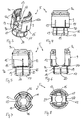
- the receiving part body 5 comprises a rod receiving portion 9 which is substantially cylindrical and which has a first end 9a and opposite second end 9b.
- the rod receiving portion 9 has a coaxial first bore 10 provided at the second end 9b.
- the diameter of the first bore 10 is smaller than the diameter of the head 3 of the bone anchoring element.
- the rod receiving portion 9 also comprises a coaxial second bore 11 extending from the first end 9a to a distance from the second end 9b.
- the diameter of the second bore 11 is larger than that of the first bore 10 and larger than the diameter of the rod 6.
- a substantially U-shaped recess 12 is provided in the rod receiving portion 9 which extends from the first end 9a to the second end 9b, the diameter of the recess 12 being slightly larger than the diameter of the rod 6 in such a way that the rod 6 can be placed in the recess and can be guided therein.
- the internal thread can be a metric thread, a flat thread, a negative angle thread, a sawtooth thread or any other thread type.
- a thread form such as a flat thread or negative angle thread is used which prevents splaying of the legs 12a, 12b when the inner screw 7 is screwed-in.
- the depth of the recess 12 is such that the rod 6 and the inner screw 7 can be inserted between the legs.
- a flat section 14 is provided forming the end of the bore 11.
- cuts 24 are provided in the rod receiving portion on either end of the channel formed by the recess 12.
- the rod receiving portion 9 of the receiving part body 5 further comprises a plurality of coaxial slits 15 extending from the second end 9b to a distance from the first end, wherein the distance corresponds approximately to the length of the internal thread 13.
- the slits 15 are open at the second end 9b and extend, as can be seen in particular in Figs. 3, 7 and 8 through the flat section 14 and the substantially U-shaped recess 12.
- At least one slit 15, preferably more than one slit is provided on either side of the recess 12.
- the number of slits is selected according to the degree of flexibility which shall be provided by the slits. It may depend on the material and the wall thickness and/or other factors.
- the receiving part body 5 Adjacent to the second end 9b the receiving part body 5 comprises a head receiving portion 16 providing an accommodation space for the head 3 of the bone anchoring element 5.
- the head receiving portion 16 has a tapering outer surface which tapers towards the second end 9b and which has an open end 17 opposite to the second end 9b.
- the exterior surface of the head receiving portion 16 can be partly or fully tapered. It is tapered at least in the region of the largest diameter of the head 3.
- the open end 17 can have a rounded edge.
- the outer diameter of the rod receiving portion 9 at its second end 9b is larger than the outer diameter of the head receiving portion 16 adjacent to the second end 9b and is also larger than the outer diameter of the head receiving portion at the open end 17.
- the head receiving portion 16 is recessed with respect to the rod receiving portion 9.
- the head receiving portion 16 has an internal hollow section 18 forming a seat for the head 3 of the bone anchoring element 1.
- the hollow section 18 is adapted in its shape to the shape of the head 3, in the embodiment shown it is a spherical section to accommodate the spherical head 3.
- the hollow section 18 is dimensioned in such a way that it encompasses the head 3 of the bone anchoring element from the side covering a region including the largest diameter of the head 3.
- a plurality of slits 19 are provided in the head receiving portion 16 which are open to the open end 17 and extend from the open end 17 to the second end 9b of the rod receiving portion and which continue in the slits 15 of the rod receiving portion 9, thereby forming continuous slits extending from the open end 17 of the head receiving portion into the rod receiving portion.
- the number of slits 19 may be equal to the number of slits 15, however, it can be smaller or larger depending on the desired flexibility of the head receiving portion 16.
- slits 20 are provided on the side of the head receiving portion 16 which is adjacent to the substantially U-shaped recess 12 of the rod receiving portion, as shown in Fig. 6 .
- the slits 20 end at a distance of the second end 9b.
- the flexibility of the head receiving portion 16 is such that the head 3 of the anchoring element can be inserted by expanding the head receiving portion and can be clamped by compressing the head receiving portion.
- the slits 15 in the rod receiving portion facilitate mounting of the receiving part body 5 onto the head 3 manually, for example at any time before or during surgery.
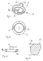
- the locking ring 8 will now be described with reference to Figs. 1 and 9 to 12 .
- the locking ring 8 has a substantially cylindrical outer surface with an outer diameter corresponding substantially to the outer diameter of the rod receiving portion 9 of the receiving part body 5.
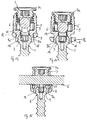
- the height of the locking ring 8 in an axial direction is smaller than that of the head receiving portion 16 of the receiving part body 5, so that, as shown in Fig. 2 and 14 , there is a distance between the locking ring 8 and the second end 9b of the receiving part 5, when the locking ring 8 is in a second end position P 2 in which the head 3 is locked.
- the locking ring 8 has on its inner side a curved interior surface portion 8a.
- the curvature is directed to the center of the locking ring.
- the curved interior surface portion 8a can have a spherical curvature. Other types of curvatures are also possible.
- the curvature is spherical.
- the radius of the curvature is smaller than the radius of the head 3.
- the dimensions of the locking ring with respect to its inner portions are such that the locking ring 8 can slide along the outer surface of the head receiving portion 16 thereby compressing the head receiving portion 16 increasingly when sliding downward.
- the locking ring 8 further comprises on its side facing the second end 9b two projections 21 located diametrically opposite to each other.
- the projections 21 have such a height that they project above the bottom of the substantially U-shaped recess 12 and extend into the cuts 24 when the locking ring 8 is in a position in which the head 3 is not yet clamped.
- the free end 22 of the projections 21 can be curved, particularly inwardly curved, with a curvature corresponding to that of the rod 6.
- the locking ring is arranged in such a way around the head receiving portion 16 of the receiving part body 5 that the projections are located at the positions of the recess 12. By means of this, the projections 21 which project into the recess 12 prevent the locking ring from rotating when the rod is not inserted.
- the flexibility of the head receiving portion 16 and the size of the head receiving portion at the open end 17 allows to mount the locking ring 8 by assembling it from the free end 17 onto the head receiving portion 16. Since the outer diameter of the head receiving portion is smaller than that of the rod receiving portion 9, the locking ring does not project or only minimally projects beyond the rod receiving portion in a radial direction.
- the locking ring 8 may have a tapered exterior surface portion 8b as shown in Fig. 11 to further reduce its diameter in the direction of the open end 17.
- the locking ring When the rod is not yet inserted or not pressed into the recess 12, the locking ring is movable between a first position P 1 as shown in Fig. 13 limited by the second end 9b of the rod receiving part which acts as a stop and a second position P 2 near the open end 17 of the head receiving portion as shown in Fig. 14 which is defined by the locking of the head 3 by means of compression of head receiving portion.
- the tapered exterior surface of the head receiving portion prevents escaping of the locking ring in the direction of the open end 17.
- the inner screw 7 has a thread corresponding to the internal thread 13 provided on the legs. If a thread form which prevents the legs from splaying is used, a single closure element such as the inner screw 7 is sufficient. This reduces the size of the bone anchoring device in a radial direction. As shown in particular in Fig. 1 , the inner screw 7 has on its side opposite to the rod 6 a rim 7a which can act as a stop for screwing in the inner screw. Also, the rim 7a facilitates gripping.
- the receiving part body 5, the locking ring 8, the inner screw 7 and the bone anchoring element 1 are made of a bio-compatible material, for example, of titanium or stainless steel or bio-compatible alloy or bio-compatible plastic material with sufficient strength.
- the bone anchoring device may be preassembled with the locking ring 8 mounted on the head receiving portion 16 of the receiving part body 5 from the open end 17.
- the bone anchoring element 1 can be preassembled with the receiving part 5 and the locking ring 8.
- the locking of the head 3 is now explained with respect to Figs. 13 to 16 .
- the locking ring 8 When the locking ring 8 is in its first end position P 1 near the second end 9b of the rod receiving portion, the locking ring 8 does not compress the head receiving portion.
- the curved portion 8a does not or does only minimally contact the exterior surface portion of the head receiving portion as shown in Fig. 13 .
- the rod 6 is not yet pressed down by tightening the inner screw 7. In this condition the head 3 of the bone anchoring element is fully pivotable within the hollow portion 18.
- the inner screw When the inner screw is tightened, it presses onto the rod 6 which presses onto the locking ring 8 via the projections 21. In the course of tightening the inner screw 7 the locking ring 8 is shifted downward until the curved portion 8a engages the tapered exterior surface portion of the head receiving portion 16.
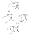
- the pressure exerted by the curved portion 8a of the locking ring onto the head receiving portion 3 is largest as shown by the arrows in Fig. 16 , whereby the head 3 is clamped in such a way that it is locked. Simultaneously, a further downward movement of the locking ring 8 is prevented as shown in Fig. 14 and 16 .
- Figures 17 and 18 show the force distribution indicated by arrows in the case that the locking ring has an internal tapered surface portion as known from the prior art.
- the locking ring 8' contacts the tapered exterior surface portion of the head receiving portion near the open end 17.
- the clamping force is largest near the open end 17 and not at the position P 2 of the largest diameter.
- the exterior tapered surface of the locking ring 8' contacts the tapered exterior surface portion of the head receiving portion above the position P 2 of the largest diameter which also results in that the force is diminishing towards the position with the largest diameter.
- the tapered surfaces of the head receiving portion and the locking ring 8' are parallel which results in a uniform pressure distribution.
- the pressure distribution of the locking ring exerted onto the head receiving portion according to the invention as shown in Fig. 16 has a maximum pressure at the position P 2 where the maximum diameter of the head 3 is located.
- the bone anchoring device can be used in several ways. In one way of use the bone anchoring element, the receiving part body and the locking ring are preassembled. The bone anchoring element is screwed into the bone with the receiving part mounted to the anchoring element. The recess 4 of the head can be accessed with the screwing-in-tool through the first bore 10. The locking ring is in its first position close to the second end 9b where it does not clamp the head 3. The flexible receiving part creates a slight pretension having a small overlap on the inner curved surface of the hollow portion 18. In this state the head 3 is pivotably held in the second portion 16 which allows the receiving part body 5 to be safely aligned to receive the rod.
- the inner screw 7 is screwed between the legs until it presses onto the rod.
- the rod is pressed against the bottom of the substantially U-shaped recess thereby engaging the free ends 22 of the projections 21 respectively, and shifting down the locking ring.
- the locking ring 8 is moved towards the free end 17 of the second portion it compresses the second portion 16 thereby clamping the head. Since the force which is exerted by the locking ring acts with the interior curved surface 8a from the lateral side, the force necessary for safely immobilizing the head is smaller than in the case in which the force acts from above on the top of the head 3. It also allows to downsize the device by allowing the wall thickness of the receiving part to be reduced. Final tightening of the inner screw locks the rod and the head simultaneously.
- the receiving part body 5 and the locking ring 8 are preassembled.
- the bone anchoring element 3 is first screwed into the bone and then the receiving part is mounted onto the head 3 while the locking ring is in its first position closed to the second end 9b and does not compress the second portion 16.
- the bone anchoring element 1 and the receiving part body with the preassembled locking ring are assembled by pressing the receiving part onto the head 3. This allows to select the appropriate bone anchoring element in terms of diameter ,length and other features of the anchoring section.
- a modular system can be provided including receiving parts and several bone anchoring elements, which then individually can be chosen and adapted.
- the inner screw is tightened to lock the head and the rod. Thereafter, the inner screw is loosened to allow further adjustments of the rod. The head remains temporarily clamped due to the frictional force which holds the locking ring in place.
- Figures 20 to 26 show a second embodiment of a bone anchoring device. Portions and elements which are identical to the first embodiment are designated with the same reference numerals as in the description of the first embodiment. The description thereof will not be repeated.
- the second embodiment differs from the first embodiment with respect to the receiving part body and the locking ring.
- the receiving part body 50 has on its face forming the second end 9b of the rod receiving portion an annular projection 30 projecting downwards which is arranged at a distance from the exterior surface of the head receiving portion adjacent to the second end 9b.
- the projection 30 has a curved exterior surface 30a forming a nose 31 which cooperates with a groove with projecting upper edge 31 at the upper portion of the curved portion 8a of the locking ring 80.
- the position and the size of the nose 30a and the edge 31 are such that a resilient engagement is possible which allows to temporarily fix the locking ring at its first end position P 1 and to release it upon exerting pressure with the rod.
- the locking ring 80 is in its upper end position P 1 releaseably held by the engagement of the edge with the nose.
- pressing down the rod leads to disengagement of the edge and nose and the rod can be moved into its second end position P 2 where it locks the head.
- the projections of the locking ring which engage the rod can have another shape.
- the surface of the free end can be flat or otherwise shaped.
- the head receiving portion can have an inclined open end 17 to allow a greater angulation of the head in one direction.
Landscapes
- Health & Medical Sciences (AREA)
- Orthopedic Medicine & Surgery (AREA)
- Life Sciences & Earth Sciences (AREA)
- Surgery (AREA)
- Neurology (AREA)
- Heart & Thoracic Surgery (AREA)
- Engineering & Computer Science (AREA)
- Biomedical Technology (AREA)
- Nuclear Medicine, Radiotherapy & Molecular Imaging (AREA)
- Medical Informatics (AREA)
- Molecular Biology (AREA)
- Animal Behavior & Ethology (AREA)
- General Health & Medical Sciences (AREA)
- Public Health (AREA)
- Veterinary Medicine (AREA)
- Surgical Instruments (AREA)
- Prostheses (AREA)
Priority Applications (8)
| Application Number | Priority Date | Filing Date | Title |
|---|---|---|---|
| ES08020737T ES2403194T3 (es) | 2008-11-28 | 2008-11-28 | Componente receptor para recibir una varilla para su acoplamiento con un elemento de anclaje de huesos y un sistema de anclaje de huesos con este componente receptor |
| EP08020737A EP2191780B1 (de) | 2008-11-28 | 2008-11-28 | Aufnahmeteil für die Aufnahme einer Stange zur Kopplung der Stange mit einem Knochenverankerungselement und eine Knochenverankerungsvorrichtung mit einem derartigen Aufnahmeteil |
| TW098139842A TW201019888A (en) | 2008-11-28 | 2009-11-24 | Receiving part for receiving a rod for coupling the rod to a bone anchoring element and a bone anchoring device with such a receiving part |
| KR20090113970A KR101508629B1 (ko) | 2008-11-28 | 2009-11-24 | 뼈 고정 요소에 로드를 결합하기 위하여 로드를 수용하기 위한 수용부와 이러한 수용부를 가진 뼈 고정 장치 |
| CN2009102250424A CN101744657B (zh) | 2008-11-28 | 2009-11-24 | 将杆连到骨锚固元件的接收部及带该接收部的骨锚固装置 |
| JP2009266167A JP5613401B2 (ja) | 2008-11-28 | 2009-11-24 | ロッドを受けてそのロッドを骨固定要素に連結するための受け部、およびそのような受け部を有する骨固定装置 |
| US12/626,830 US8636781B2 (en) | 2008-11-28 | 2009-11-27 | Receiving part for receiving a rod for coupling the rod to a bone anchoring element and a bone anchoring device with such a receiving part |
| US14/147,371 US8998967B2 (en) | 2008-11-28 | 2014-01-03 | Receiving part for receiving a rod for coupling the rod to a bone anchoring element and a bone anchoring device with such a receiving part |
Applications Claiming Priority (1)
| Application Number | Priority Date | Filing Date | Title |
|---|---|---|---|
| EP08020737A EP2191780B1 (de) | 2008-11-28 | 2008-11-28 | Aufnahmeteil für die Aufnahme einer Stange zur Kopplung der Stange mit einem Knochenverankerungselement und eine Knochenverankerungsvorrichtung mit einem derartigen Aufnahmeteil |
Publications (2)
| Publication Number | Publication Date |
|---|---|
| EP2191780A1 true EP2191780A1 (de) | 2010-06-02 |
| EP2191780B1 EP2191780B1 (de) | 2013-01-16 |
Family
ID=40521870
Family Applications (1)
| Application Number | Title | Priority Date | Filing Date |
|---|---|---|---|
| EP08020737A Active EP2191780B1 (de) | 2008-11-28 | 2008-11-28 | Aufnahmeteil für die Aufnahme einer Stange zur Kopplung der Stange mit einem Knochenverankerungselement und eine Knochenverankerungsvorrichtung mit einem derartigen Aufnahmeteil |
Country Status (7)
| Country | Link |
|---|---|
| US (2) | US8636781B2 (de) |
| EP (1) | EP2191780B1 (de) |
| JP (1) | JP5613401B2 (de) |
| KR (1) | KR101508629B1 (de) |
| CN (1) | CN101744657B (de) |
| ES (1) | ES2403194T3 (de) |
| TW (1) | TW201019888A (de) |
Cited By (4)
| Publication number | Priority date | Publication date | Assignee | Title |
|---|---|---|---|---|
| US8881358B2 (en) | 2010-05-05 | 2014-11-11 | Biedermann Technologies Gmbh & Co. Kg | Method and tool for assembling a bone anchoring device |
| US8940024B2 (en) | 2007-07-31 | 2015-01-27 | Biedermann Technologies Gmbh & Co. Kg | Bone anchoring device |
| US9173684B2 (en) | 2010-12-10 | 2015-11-03 | Biedermann Technologies Gmbh & Co. Kg | Receiving part for receiving a rod for coupling the rod to a bone anchoring element and bone anchoring device with such a receiving part |
| EP3106110A1 (de) | 2015-06-16 | 2016-12-21 | Biedermann Technologies GmbH & Co. KG | Verlängerungsvorrichtung für einen knochenanker |
Families Citing this family (23)
| Publication number | Priority date | Publication date | Assignee | Title |
|---|---|---|---|---|
| ES2473915T3 (es) * | 2010-12-10 | 2014-07-08 | Biedermann Technologies Gmbh & Co. Kg | Pieza receptora para recibir y alojar una barra con el fin de acoplarla a un elemento de anclaje de hueso y dispositivo de anclaje de hueso con dicha pieza receptora |
| EP2918237A1 (de) * | 2011-09-15 | 2015-09-16 | Biedermann Technologies GmbH & Co. KG | Mehrachsige knochenverankerungsvorrichtung mit vergrössertem schwenkwinkel |
| EP2574297B1 (de) * | 2011-09-30 | 2015-11-11 | Biedermann Technologies GmbH & Co. KG | Knochenverankerungsvorrichtung und Werkzeug, das mit der Knochenverankerungsvorrichtung arbeitet |
| JP2014533136A (ja) | 2011-10-05 | 2014-12-11 | マーク・エイ・ドッドソン | モジュール開創器および関連する方法 |
| EP2591738A1 (de) * | 2011-11-14 | 2013-05-15 | Biedermann Technologies GmbH & Co. KG | Polyaxiale Knochenverankerungsvorrichtung |
| JP2015166673A (ja) * | 2012-07-06 | 2015-09-24 | パナソニック株式会社 | 検出対象体の取付装置および自転車 |
| US9566092B2 (en) * | 2013-10-29 | 2017-02-14 | Roger P. Jackson | Cervical bone anchor with collet retainer and outer locking sleeve |
| US9498255B2 (en) * | 2013-12-31 | 2016-11-22 | Blackstone Medical, Inc. | Translational pedicle screw systems |
| FR3035318B1 (fr) * | 2015-04-24 | 2017-05-19 | Medicrea Int | Materiel d'osteosynthese vertebrale |
| US9707013B2 (en) * | 2015-04-30 | 2017-07-18 | Warsaw Orthopedic, Inc. | Spinal implant system and methods of use |
| EP3103406B1 (de) | 2015-06-10 | 2017-10-04 | Biedermann Technologies GmbH & Co. KG | Aufnahmeteil einer knochenverankerungsvorrichtung und knochenverankerungsvorrichtung mit solch einem aufnahmeteil |
| EP3473198B1 (de) * | 2016-08-04 | 2023-02-22 | Biedermann Technologies GmbH & Co. KG | Vorrichtung zur polyaxialen knochenverankerung und system eines instruments und eine vorrichtung zur polyaxialen knochenverankerung |
| EP3287089B1 (de) * | 2016-08-24 | 2019-07-24 | Biedermann Technologies GmbH & Co. KG | Vorrichtung zur polyaxialen knochenverankerung und system eines instruments und eine vorrichtung zur polyaxialen knochenverankerung |
| WO2018183314A1 (en) | 2017-03-30 | 2018-10-04 | K2M, Inc. | Bone anchor apparatus and method of use thereof |
| US11298156B2 (en) | 2017-03-30 | 2022-04-12 | K2M, Inc. | Modular screw |
| US11419639B2 (en) | 2017-03-30 | 2022-08-23 | K2M, Inc. | Modular offset screw |
| EP3476340B1 (de) | 2017-10-25 | 2021-06-02 | Biedermann Technologies GmbH & Co. KG | Polyaxiale knochenverankerungsvorrichtung |
| EP3536271B1 (de) | 2018-03-06 | 2022-05-04 | Biedermann Technologies GmbH & Co. KG | Vorrichtung zur polyaxialen knochenverankerung und system eines instruments und eine vorrichtung zur polyaxialen knochenverankerung |
| US11204060B2 (en) * | 2019-11-27 | 2021-12-21 | Medos International Sari | Selectively lockable ball and socket joint |
| US12262921B2 (en) | 2020-06-26 | 2025-04-01 | K2M, Inc. | Modular head assembly |
| WO2022108875A1 (en) | 2020-11-19 | 2022-05-27 | K2M, Inc. | Modular head assembly for spinal fixation |
| EP4129220B1 (de) * | 2021-08-04 | 2024-07-03 | Biedermann Technologies GmbH & Co. KG | Kupplungsvorrichtung zum koppeln einer stange mit einem knochenverankerungselement und verfahren zur herstellung davon |
| WO2025018540A1 (ko) * | 2023-07-20 | 2025-01-23 | (주)시지바이오 | 척추경 나사못 조립체 |
Citations (15)
| Publication number | Priority date | Publication date | Assignee | Title |
|---|---|---|---|---|
| US4946458A (en) | 1986-04-25 | 1990-08-07 | Harms Juergen | Pedicle screw |
| US5443467A (en) | 1993-03-10 | 1995-08-22 | Biedermann Motech Gmbh | Bone screw |
| US5549608A (en) | 1995-07-13 | 1996-08-27 | Fastenetix, L.L.C. | Advanced polyaxial locking screw and coupling element device for use with rod fixation apparatus |
| US5672179A (en) | 1991-05-07 | 1997-09-30 | Laerdal Medical Corporation | Intubation device having stiffening member |
| US5728098A (en) | 1996-11-07 | 1998-03-17 | Sdgi Holdings, Inc. | Multi-angle bone screw assembly using shape-memory technology |
| US5733285A (en) | 1995-07-13 | 1998-03-31 | Fastenetix, Llc | Polyaxial locking mechanism |
| US6063090A (en) | 1996-12-12 | 2000-05-16 | Synthes (U.S.A.) | Device for connecting a longitudinal support to a pedicle screw |
| US20010047173A1 (en) * | 1998-09-29 | 2001-11-29 | Fridolin Schlapfer | Device for connecting a longitudinal support to a bone anchor |
| WO2004089245A2 (en) * | 2003-04-04 | 2004-10-21 | Theken Surgical, Llc | Bone anchor |
| US20050080415A1 (en) | 2003-10-14 | 2005-04-14 | Keyer Thomas R. | Polyaxial bone anchor and method of spinal fixation |
| WO2005041821A2 (en) * | 2003-11-03 | 2005-05-12 | Spinal, Llc | Bone fixation system with low profile fastener |
| US20050228392A1 (en) * | 2004-04-12 | 2005-10-13 | Keyer Thomas R | Rod persuader |
| WO2007038350A2 (en) | 2005-09-23 | 2007-04-05 | Synthes (Usa) | Bone support apparatus |
| US20080243193A1 (en) * | 2005-05-25 | 2008-10-02 | Ensign Michael D | Low Profile Pedicle Screw Assembly |
| EP2022423A1 (de) * | 2007-07-31 | 2009-02-11 | BIEDERMANN MOTECH GmbH | Knochenverankerungsvorrichtung |
Family Cites Families (17)
| Publication number | Priority date | Publication date | Assignee | Title |
|---|---|---|---|---|
| US5879350A (en) * | 1996-09-24 | 1999-03-09 | Sdgi Holdings, Inc. | Multi-axial bone screw assembly |
| DE59712497D1 (de) | 1997-01-22 | 2005-12-29 | Synthes Ag | Vorrichtung zur verbindung eines langsträgers mit einer pedikelschraube |
| US6254602B1 (en) | 1999-05-28 | 2001-07-03 | Sdgi Holdings, Inc. | Advanced coupling device using shape-memory technology |
| US7087057B2 (en) | 2003-06-27 | 2006-08-08 | Depuy Acromed, Inc. | Polyaxial bone screw |
| US7503924B2 (en) | 2004-04-08 | 2009-03-17 | Globus Medical, Inc. | Polyaxial screw |
| US8475495B2 (en) | 2004-04-08 | 2013-07-02 | Globus Medical | Polyaxial screw |
| US20060084978A1 (en) | 2004-09-30 | 2006-04-20 | Mokhtar Mourad B | Spinal fixation system and method |
| US7572280B2 (en) | 2004-10-05 | 2009-08-11 | Warsaw Orthopedic, Inc. | Multi-axial anchor assemblies for spinal implants and methods |
| US7445627B2 (en) | 2005-01-31 | 2008-11-04 | Alpinespine, Llc | Polyaxial pedicle screw assembly |
| US7476239B2 (en) | 2005-05-10 | 2009-01-13 | Jackson Roger P | Polyaxial bone screw with compound articulation |
| CA2605875A1 (en) * | 2005-04-29 | 2006-11-09 | Charles A. Dickinson | Multi-axial anchor assemblies for spinal implants and methods |
| US7850715B2 (en) | 2005-04-29 | 2010-12-14 | Warsaw Orthopedic Inc. | Orthopedic implant apparatus |
| US7625394B2 (en) * | 2005-08-05 | 2009-12-01 | Warsaw Orthopedic, Inc. | Coupling assemblies for spinal implants |
| US7922748B2 (en) | 2006-06-16 | 2011-04-12 | Zimmer Spine, Inc. | Removable polyaxial housing for a pedicle screw |
| US8167910B2 (en) | 2006-10-16 | 2012-05-01 | Innovative Delta Technology Llc | Bone screw and associated assembly and methods of use thereof |
| US20080269742A1 (en) | 2007-04-25 | 2008-10-30 | Levy Mark M | Connector assembly for bone anchoring element |
| US8083777B2 (en) | 2007-06-15 | 2011-12-27 | Robert Reid, Inc. | System and method for polyaxially adjustable bone anchorage |
-
2008
- 2008-11-28 EP EP08020737A patent/EP2191780B1/de active Active
- 2008-11-28 ES ES08020737T patent/ES2403194T3/es active Active
-
2009
- 2009-11-24 JP JP2009266167A patent/JP5613401B2/ja not_active Expired - Fee Related
- 2009-11-24 KR KR20090113970A patent/KR101508629B1/ko not_active Expired - Fee Related
- 2009-11-24 TW TW098139842A patent/TW201019888A/zh unknown
- 2009-11-24 CN CN2009102250424A patent/CN101744657B/zh not_active Expired - Fee Related
- 2009-11-27 US US12/626,830 patent/US8636781B2/en active Active
-
2014
- 2014-01-03 US US14/147,371 patent/US8998967B2/en active Active
Patent Citations (15)
| Publication number | Priority date | Publication date | Assignee | Title |
|---|---|---|---|---|
| US4946458A (en) | 1986-04-25 | 1990-08-07 | Harms Juergen | Pedicle screw |
| US5672179A (en) | 1991-05-07 | 1997-09-30 | Laerdal Medical Corporation | Intubation device having stiffening member |
| US5443467A (en) | 1993-03-10 | 1995-08-22 | Biedermann Motech Gmbh | Bone screw |
| US5549608A (en) | 1995-07-13 | 1996-08-27 | Fastenetix, L.L.C. | Advanced polyaxial locking screw and coupling element device for use with rod fixation apparatus |
| US5733285A (en) | 1995-07-13 | 1998-03-31 | Fastenetix, Llc | Polyaxial locking mechanism |
| US5728098A (en) | 1996-11-07 | 1998-03-17 | Sdgi Holdings, Inc. | Multi-angle bone screw assembly using shape-memory technology |
| US6063090A (en) | 1996-12-12 | 2000-05-16 | Synthes (U.S.A.) | Device for connecting a longitudinal support to a pedicle screw |
| US20010047173A1 (en) * | 1998-09-29 | 2001-11-29 | Fridolin Schlapfer | Device for connecting a longitudinal support to a bone anchor |
| WO2004089245A2 (en) * | 2003-04-04 | 2004-10-21 | Theken Surgical, Llc | Bone anchor |
| US20050080415A1 (en) | 2003-10-14 | 2005-04-14 | Keyer Thomas R. | Polyaxial bone anchor and method of spinal fixation |
| WO2005041821A2 (en) * | 2003-11-03 | 2005-05-12 | Spinal, Llc | Bone fixation system with low profile fastener |
| US20050228392A1 (en) * | 2004-04-12 | 2005-10-13 | Keyer Thomas R | Rod persuader |
| US20080243193A1 (en) * | 2005-05-25 | 2008-10-02 | Ensign Michael D | Low Profile Pedicle Screw Assembly |
| WO2007038350A2 (en) | 2005-09-23 | 2007-04-05 | Synthes (Usa) | Bone support apparatus |
| EP2022423A1 (de) * | 2007-07-31 | 2009-02-11 | BIEDERMANN MOTECH GmbH | Knochenverankerungsvorrichtung |
Cited By (8)
| Publication number | Priority date | Publication date | Assignee | Title |
|---|---|---|---|---|
| US8940024B2 (en) | 2007-07-31 | 2015-01-27 | Biedermann Technologies Gmbh & Co. Kg | Bone anchoring device |
| US9289246B2 (en) | 2007-07-31 | 2016-03-22 | Biedermann Technologies Gmbh & Co. Kg | Bone anchoring device |
| US8881358B2 (en) | 2010-05-05 | 2014-11-11 | Biedermann Technologies Gmbh & Co. Kg | Method and tool for assembling a bone anchoring device |
| US9381043B2 (en) | 2010-05-05 | 2016-07-05 | Biedermann Technologies Gmbh & Co. Kg | Insert for a tool for assembling a bone anchoring device and tool for assembling a bone anchoring device |
| US9566091B2 (en) | 2010-05-05 | 2017-02-14 | Biedermann Technologies Gmbh & Co. Kg | Method and tool for assembling a bone anchoring device |
| US9173684B2 (en) | 2010-12-10 | 2015-11-03 | Biedermann Technologies Gmbh & Co. Kg | Receiving part for receiving a rod for coupling the rod to a bone anchoring element and bone anchoring device with such a receiving part |
| EP3106110A1 (de) | 2015-06-16 | 2016-12-21 | Biedermann Technologies GmbH & Co. KG | Verlängerungsvorrichtung für einen knochenanker |
| US9999451B2 (en) | 2015-06-16 | 2018-06-19 | Biedermann Technologies Gmbh & Co. Kg | Extension device for a bone anchor |
Also Published As
| Publication number | Publication date |
|---|---|
| TW201019888A (en) | 2010-06-01 |
| US8998967B2 (en) | 2015-04-07 |
| ES2403194T3 (es) | 2013-05-16 |
| CN101744657A (zh) | 2010-06-23 |
| JP5613401B2 (ja) | 2014-10-22 |
| JP2010125328A (ja) | 2010-06-10 |
| US8636781B2 (en) | 2014-01-28 |
| US20100160975A1 (en) | 2010-06-24 |
| US20140296927A1 (en) | 2014-10-02 |
| KR101508629B1 (ko) | 2015-04-06 |
| CN101744657B (zh) | 2013-06-19 |
| KR20100061354A (ko) | 2010-06-07 |
| EP2191780B1 (de) | 2013-01-16 |
Similar Documents
| Publication | Publication Date | Title |
|---|---|---|
| EP2191780B1 (de) | Aufnahmeteil für die Aufnahme einer Stange zur Kopplung der Stange mit einem Knochenverankerungselement und eine Knochenverankerungsvorrichtung mit einem derartigen Aufnahmeteil | |
| EP2526881B1 (de) | Aufnahmeteil für die Aufnahme einer Stange zur Kopplung der Stange in einem Knochenverankerungselement und Knochenverankerungsvorrichtung mit einem derartigen Aufnahmeteil | |
| US8940024B2 (en) | Bone anchoring device | |
| US8506610B2 (en) | Receiving part for receiving a rod for coupling the rod to a bone anchoring element and a bone anchoring device with such a receiving part | |
| EP2204129B1 (de) | Aufnahmeteil für die Aufnahme einer Stange zur Kopplung der Stange in einem Knochenverankerungselement und eine Knochenverankerungsvorrichtung mit einem derartigen Aufnahmeteil | |
| EP1741396B1 (de) | Knochenverankerungsvorrichtung | |
| US9173684B2 (en) | Receiving part for receiving a rod for coupling the rod to a bone anchoring element and bone anchoring device with such a receiving part | |
| EP1749489B1 (de) | Knochenverankerungsvorrichtung |
Legal Events
| Date | Code | Title | Description |
|---|---|---|---|
| PUAI | Public reference made under article 153(3) epc to a published international application that has entered the european phase |
Free format text: ORIGINAL CODE: 0009012 |
|
| AK | Designated contracting states |
Kind code of ref document: A1 Designated state(s): AT BE BG CH CY CZ DE DK EE ES FI FR GB GR HR HU IE IS IT LI LT LU LV MC MT NL NO PL PT RO SE SI SK TR |
|
| AX | Request for extension of the european patent |
Extension state: AL BA MK RS |
|
| 17P | Request for examination filed |
Effective date: 20100630 |
|
| 17Q | First examination report despatched |
Effective date: 20100728 |
|
| AKX | Designation fees paid |
Designated state(s): CH DE ES FR GB IT LI |
|
| RAP1 | Party data changed (applicant data changed or rights of an application transferred) |
Owner name: BIEDERMANN TECHNOLOGIES GMBH & CO. KG |
|
| GRAP | Despatch of communication of intention to grant a patent |
Free format text: ORIGINAL CODE: EPIDOSNIGR1 |
|
| GRAS | Grant fee paid |
Free format text: ORIGINAL CODE: EPIDOSNIGR3 |
|
| GRAA | (expected) grant |
Free format text: ORIGINAL CODE: 0009210 |
|
| AK | Designated contracting states |
Kind code of ref document: B1 Designated state(s): CH DE ES FR GB IT LI |
|
| REG | Reference to a national code |
Ref country code: GB Ref legal event code: FG4D |
|
| REG | Reference to a national code |
Ref country code: CH Ref legal event code: EP Ref country code: CH Ref legal event code: NV Representative=s name: NOVAGRAAF INTERNATIONAL SA, CH |
|
| REG | Reference to a national code |
Ref country code: CH Ref legal event code: NV Representative=s name: NOVAGRAAF INTERNATIONAL SA, CH Ref country code: CH Ref legal event code: EP |
|
| REG | Reference to a national code |
Ref country code: DE Ref legal event code: R096 Ref document number: 602008021665 Country of ref document: DE Effective date: 20130314 |
|
| REG | Reference to a national code |
Ref country code: ES Ref legal event code: FG2A Ref document number: 2403194 Country of ref document: ES Kind code of ref document: T3 Effective date: 20130516 |
|
| PLBE | No opposition filed within time limit |
Free format text: ORIGINAL CODE: 0009261 |
|
| STAA | Information on the status of an ep patent application or granted ep patent |
Free format text: STATUS: NO OPPOSITION FILED WITHIN TIME LIMIT |
|
| 26N | No opposition filed |
Effective date: 20131017 |
|
| REG | Reference to a national code |
Ref country code: DE Ref legal event code: R097 Ref document number: 602008021665 Country of ref document: DE Effective date: 20131017 |
|
| REG | Reference to a national code |
Ref country code: FR Ref legal event code: PLFP Year of fee payment: 8 |
|
| REG | Reference to a national code |
Ref country code: FR Ref legal event code: PLFP Year of fee payment: 9 |
|
| PGFP | Annual fee paid to national office [announced via postgrant information from national office to epo] |
Ref country code: FR Payment date: 20161124 Year of fee payment: 9 |
|
| PGFP | Annual fee paid to national office [announced via postgrant information from national office to epo] |
Ref country code: IT Payment date: 20161124 Year of fee payment: 9 Ref country code: ES Payment date: 20161124 Year of fee payment: 9 |
|
| REG | Reference to a national code |
Ref country code: FR Ref legal event code: ST Effective date: 20180731 |
|
| PG25 | Lapsed in a contracting state [announced via postgrant information from national office to epo] |
Ref country code: FR Free format text: LAPSE BECAUSE OF NON-PAYMENT OF DUE FEES Effective date: 20171130 Ref country code: IT Free format text: LAPSE BECAUSE OF NON-PAYMENT OF DUE FEES Effective date: 20171128 |
|
| REG | Reference to a national code |
Ref country code: ES Ref legal event code: FD2A Effective date: 20190103 |
|
| PG25 | Lapsed in a contracting state [announced via postgrant information from national office to epo] |
Ref country code: ES Free format text: LAPSE BECAUSE OF NON-PAYMENT OF DUE FEES Effective date: 20171129 |
|
| P01 | Opt-out of the competence of the unified patent court (upc) registered |
Effective date: 20230525 |
|
| REG | Reference to a national code |
Ref country code: CH Ref legal event code: U11 Free format text: ST27 STATUS EVENT CODE: U-0-0-U10-U11 (AS PROVIDED BY THE NATIONAL OFFICE) Effective date: 20251201 |
|
| PGFP | Annual fee paid to national office [announced via postgrant information from national office to epo] |
Ref country code: DE Payment date: 20251126 Year of fee payment: 18 |
|
| PGFP | Annual fee paid to national office [announced via postgrant information from national office to epo] |
Ref country code: GB Payment date: 20251114 Year of fee payment: 18 |
|
| PGFP | Annual fee paid to national office [announced via postgrant information from national office to epo] |
Ref country code: CH Payment date: 20251201 Year of fee payment: 18 |