EP2191911B1 - Noyaux de moulage par coulée de précision et procédés - Google Patents
Noyaux de moulage par coulée de précision et procédés Download PDFInfo
- Publication number
- EP2191911B1 EP2191911B1 EP09252636.7A EP09252636A EP2191911B1 EP 2191911 B1 EP2191911 B1 EP 2191911B1 EP 09252636 A EP09252636 A EP 09252636A EP 2191911 B1 EP2191911 B1 EP 2191911B1
- Authority
- EP
- European Patent Office
- Prior art keywords
- casting core
- metallic
- investment casting
- depth
- compartments
- Prior art date
- Legal status (The legal status is an assumption and is not a legal conclusion. Google has not performed a legal analysis and makes no representation as to the accuracy of the status listed.)
- Active
Links
- 238000000034 method Methods 0.000 title claims description 23
- 238000005495 investment casting Methods 0.000 title claims description 22
- 238000005266 casting Methods 0.000 claims description 40
- 239000000919 ceramic Substances 0.000 claims description 22
- 239000000463 material Substances 0.000 claims description 10
- 238000000465 moulding Methods 0.000 claims description 8
- 238000004519 manufacturing process Methods 0.000 claims description 7
- 229910045601 alloy Inorganic materials 0.000 claims description 6
- 239000000956 alloy Substances 0.000 claims description 6
- 230000013011 mating Effects 0.000 claims description 4
- 238000001816 cooling Methods 0.000 description 10
- 239000003870 refractory metal Substances 0.000 description 5
- OKTJSMMVPCPJKN-UHFFFAOYSA-N Carbon Chemical compound [C] OKTJSMMVPCPJKN-UHFFFAOYSA-N 0.000 description 4
- 230000008901 benefit Effects 0.000 description 4
- 229910052799 carbon Inorganic materials 0.000 description 4
- 238000000576 coating method Methods 0.000 description 4
- 238000005520 cutting process Methods 0.000 description 4
- 239000007789 gas Substances 0.000 description 4
- 229910000601 superalloy Inorganic materials 0.000 description 4
- 239000000853 adhesive Substances 0.000 description 3
- 230000001070 adhesive effect Effects 0.000 description 3
- 239000011248 coating agent Substances 0.000 description 3
- 238000003754 machining Methods 0.000 description 3
- 239000002002 slurry Substances 0.000 description 3
- CURLTUGMZLYLDI-UHFFFAOYSA-N Carbon dioxide Chemical compound O=C=O CURLTUGMZLYLDI-UHFFFAOYSA-N 0.000 description 2
- VYPSYNLAJGMNEJ-UHFFFAOYSA-N Silicium dioxide Chemical compound O=[Si]=O VYPSYNLAJGMNEJ-UHFFFAOYSA-N 0.000 description 2
- MCMNRKCIXSYSNV-UHFFFAOYSA-N Zirconium dioxide Chemical compound O=[Zr]=O MCMNRKCIXSYSNV-UHFFFAOYSA-N 0.000 description 2
- PNEYBMLMFCGWSK-UHFFFAOYSA-N aluminium oxide Inorganic materials [O-2].[O-2].[O-2].[Al+3].[Al+3] PNEYBMLMFCGWSK-UHFFFAOYSA-N 0.000 description 2
- 230000000712 assembly Effects 0.000 description 2
- 238000000429 assembly Methods 0.000 description 2
- 239000011230 binding agent Substances 0.000 description 2
- 239000013078 crystal Substances 0.000 description 2
- 230000001419 dependent effect Effects 0.000 description 2
- 125000001183 hydrocarbyl group Chemical group 0.000 description 2
- 239000000203 mixture Substances 0.000 description 2
- 238000012986 modification Methods 0.000 description 2
- 230000004048 modification Effects 0.000 description 2
- 230000003647 oxidation Effects 0.000 description 2
- 238000007254 oxidation reaction Methods 0.000 description 2
- 230000001590 oxidative effect Effects 0.000 description 2
- 238000005240 physical vapour deposition Methods 0.000 description 2
- 239000000843 powder Substances 0.000 description 2
- 239000002243 precursor Substances 0.000 description 2
- 238000007711 solidification Methods 0.000 description 2
- 230000008023 solidification Effects 0.000 description 2
- 239000000126 substance Substances 0.000 description 2
- 241000588731 Hafnia Species 0.000 description 1
- 229910000760 Hardened steel Inorganic materials 0.000 description 1
- ZOKXTWBITQBERF-UHFFFAOYSA-N Molybdenum Chemical compound [Mo] ZOKXTWBITQBERF-UHFFFAOYSA-N 0.000 description 1
- QVGXLLKOCUKJST-UHFFFAOYSA-N atomic oxygen Chemical compound [O] QVGXLLKOCUKJST-UHFFFAOYSA-N 0.000 description 1
- 230000015572 biosynthetic process Effects 0.000 description 1
- 239000006227 byproduct Substances 0.000 description 1
- 229910002092 carbon dioxide Inorganic materials 0.000 description 1
- 239000001569 carbon dioxide Substances 0.000 description 1
- 230000015556 catabolic process Effects 0.000 description 1
- 238000005524 ceramic coating Methods 0.000 description 1
- 238000005229 chemical vapour deposition Methods 0.000 description 1
- 229910052804 chromium Inorganic materials 0.000 description 1
- 239000000084 colloidal system Substances 0.000 description 1
- 239000002131 composite material Substances 0.000 description 1
- 238000006731 degradation reaction Methods 0.000 description 1
- 230000001627 detrimental effect Effects 0.000 description 1
- QDOXWKRWXJOMAK-UHFFFAOYSA-N dichromium trioxide Chemical compound O=[Cr]O[Cr]=O QDOXWKRWXJOMAK-UHFFFAOYSA-N 0.000 description 1
- KZHJGOXRZJKJNY-UHFFFAOYSA-N dioxosilane;oxo(oxoalumanyloxy)alumane Chemical compound O=[Si]=O.O=[Si]=O.O=[Al]O[Al]=O.O=[Al]O[Al]=O.O=[Al]O[Al]=O KZHJGOXRZJKJNY-UHFFFAOYSA-N 0.000 description 1
- 238000007598 dipping method Methods 0.000 description 1
- 238000004090 dissolution Methods 0.000 description 1
- 238000001035 drying Methods 0.000 description 1
- 238000001962 electrophoresis Methods 0.000 description 1
- 230000003628 erosive effect Effects 0.000 description 1
- 239000000945 filler Substances 0.000 description 1
- CJNBYAVZURUTKZ-UHFFFAOYSA-N hafnium(IV) oxide Inorganic materials O=[Hf]=O CJNBYAVZURUTKZ-UHFFFAOYSA-N 0.000 description 1
- 239000011261 inert gas Substances 0.000 description 1
- 238000003698 laser cutting Methods 0.000 description 1
- 239000007788 liquid Substances 0.000 description 1
- 230000008018 melting Effects 0.000 description 1
- 238000002844 melting Methods 0.000 description 1
- 229910052751 metal Inorganic materials 0.000 description 1
- 239000002184 metal Substances 0.000 description 1
- 150000001247 metal acetylides Chemical class 0.000 description 1
- 238000005058 metal casting Methods 0.000 description 1
- 239000007769 metal material Substances 0.000 description 1
- 229910052750 molybdenum Inorganic materials 0.000 description 1
- 239000011733 molybdenum Substances 0.000 description 1
- 229910052863 mullite Inorganic materials 0.000 description 1
- 229910052758 niobium Inorganic materials 0.000 description 1
- 239000010955 niobium Substances 0.000 description 1
- GUCVJGMIXFAOAE-UHFFFAOYSA-N niobium atom Chemical compound [Nb] GUCVJGMIXFAOAE-UHFFFAOYSA-N 0.000 description 1
- 229910000510 noble metal Inorganic materials 0.000 description 1
- 229910052760 oxygen Inorganic materials 0.000 description 1
- 239000001301 oxygen Substances 0.000 description 1
- 238000010248 power generation Methods 0.000 description 1
- 230000002028 premature Effects 0.000 description 1
- 239000011253 protective coating Substances 0.000 description 1
- 230000035939 shock Effects 0.000 description 1
- 229910052710 silicon Inorganic materials 0.000 description 1
- 239000000377 silicon dioxide Substances 0.000 description 1
- 238000003980 solgel method Methods 0.000 description 1
- 239000007921 spray Substances 0.000 description 1
- 238000005507 spraying Methods 0.000 description 1
- 238000007669 thermal treatment Methods 0.000 description 1
- 210000002105 tongue Anatomy 0.000 description 1
- 229910052721 tungsten Inorganic materials 0.000 description 1
- 230000008016 vaporization Effects 0.000 description 1
- 238000009834 vaporization Methods 0.000 description 1
- 238000003466 welding Methods 0.000 description 1
Images
Classifications
-
- B—PERFORMING OPERATIONS; TRANSPORTING
- B22—CASTING; POWDER METALLURGY
- B22C—FOUNDRY MOULDING
- B22C7/00—Patterns; Manufacture thereof so far as not provided for in other classes
- B22C7/02—Lost patterns
-
- B—PERFORMING OPERATIONS; TRANSPORTING
- B22—CASTING; POWDER METALLURGY
- B22C—FOUNDRY MOULDING
- B22C9/00—Moulds or cores; Moulding processes
- B22C9/02—Sand moulds or like moulds for shaped castings
- B22C9/04—Use of lost patterns
-
- B—PERFORMING OPERATIONS; TRANSPORTING
- B22—CASTING; POWDER METALLURGY
- B22C—FOUNDRY MOULDING
- B22C9/00—Moulds or cores; Moulding processes
- B22C9/10—Cores; Manufacture or installation of cores
- B22C9/103—Multipart cores
Definitions
- the invention relates to investment casting and is useful in the investment casting of superalloy turbine engine components, for example.
- Investment casting is a commonly used technique for forming metallic components having complex geometries, especially hollow components, and is used in the fabrication of superalloy gas turbine engine components.
- the invention is described in respect to the production of particular superalloy castings, however it is understood that the invention is not so limited.
- Gas turbine engines are widely used in aircraft propulsion, electric power generation, and ship propulsion. In gas turbine engine applications, efficiency is a prime objective. Improved gas turbine engine efficiency can be obtained by operating at higher temperatures, however current operating temperatures in the turbine section exceed the melting points of the superalloy materials used in turbine components. Consequently, it is a general practice to provide air cooling. Cooling is provided by flowing relatively cool air from the compressor section of the engine through passages in the turbine components to be cooled. Such cooling comes with an associated cost in engine efficiency. Consequently, there is a strong desire to provide enhanced specific cooling, maximizing the amount of cooling benefit obtained from a given amount of cooling air. This may be obtained by the use of fine, precisely located, cooling passageway sections.
- the cooling passageway sections may be cast over casting cores.
- Ceramic casting cores may be formed by molding a mixture of ceramic powder and binder material by injecting the mixture into hardened steel dies. After removal from the dies, the green cores are thermally post-processed to remove the binder and fired to sinter the ceramic powder together.
- the trend toward finer cooling features has taxed core manufacturing techniques. The fine features may be difficult to manufacture and/or, once manufactured, may prove fragile.
- Commonly-assigned U.S. Patent Nos. 6,637,500 of Shah et al. , 6,929,054 of Beals et al. , 7,014,424 of Cunha et al. , 7,134,475 of Snyder et al. and U.S. Patent Publication No. 20060239819 of Albert et al. disclose use of ceramic and refractory metal core combinations.
- an investment casting core combination comprising: a metallic casting core having opposite first and second faces; and a ceramic feedcore in which a first region of the metallic casting core is embedded, wherein: the metallic casting core comprises a mating edge having: a plurality of projections, the first region being along at least some of the projections; and a plurality of recesses, spanning gaps between adjacent said projections; and the ceramic feedcore comprises: a plurality of compartments of depth D, respectively receiving the metallic casting core projections along said first and second faces; and a plurality of portions between the compartments and respectively received in the metallic casting core recesses, characterised in that the plurality of compartments are subdivisions of a subdivided compartment and merge along an initial portion of depth D 1 of the subdivided compartment.
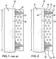
- FIG. 1 shows a prior art core assembly 20 including a ceramic feedcore 21 and an RMC (refractory metal core) 22.
- the assembly is illustrative of a feedcore forming a trailing edge slot for a blade or vane airfoil.
- a joint 23 is formed by a leading region of the exemplary RMC 22 mounted in a trailing slot 24 in the feedcore 21.
- the joint 23 may further include a filler material (such as a hardened ceramic adhesive or slurry) at one or more locations between the RMC 22 and the ceramic feedcore 21.
- the joint 23 has a length L.
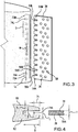
- a modified feedcore/RMC assembly 30 in accordance with the invention is shown in FIGS. 2 and 3 .
- the modified ceramic feedcore 31 may be formed by molding (e.g., as in the prior art).
- the modified RMC 32 may be formed from sheetstock and have first and second faces 36 and 38 ( FIG. 3 ) for forming an exemplary trailing edge discharge slot.
- the exemplary RMC 32 has first and second span-wise ends/edges (e.g., an inboard end 40 and an outboard end 42) and first and second streamwise ends/edges (e.g., a leading edge 44 and a trailing edge 46).
- a region 48 of the RMC (e.g., a portion near the leading end/edge 44) may be received by the feedcore.
- a region 50 e.g., near the trailing end/edge 46 may be received in the pattern forming die and, ultimately, in the shell so as to cast one or more openings in the surface of the casting.
- a main portion 52 of the RMC may cast the ultimate discharge slot.
- the region 48 comprises a plurality of projections (tabs/tongues) 54A-54M separated from each other by recesses 56A-56L.
- the exemplary projections are unitarily formed with the main portion 52 by removing adjacent material from the refractory metal sheetstock. The removal may be part of the same process that forms additional holes/apertures 58 in the RMC main portion 52 (e.g., for casting posts in the ultimate discharge slot).
- the exemplary apertures 58 are internal through-apertures. They are "internal” or “closed” in that they are not open to the lateral perimeters of the islands (e.g., along the leading and trailing edges, the inboard and outboard edges, or along the gaps).
- the RMC's mating region 48 is received in a trailing region 70 of the feedcore.
- the exemplary trailing region (receiving region) 70 comprises a subdivided compartment having individual recesses or compartments 72A-72M at least partially separated from adjacent ones of each other by dividing walls 74A-74L.
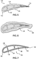
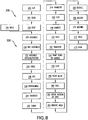
- FIG. 4 shows each compartment 72A-72M as having a height (or height profile) H and a depth D.
- FIG. 3 shows each compartment 72A-72M as having a spanwise length or depth-dependent length profile L C .
- the compartments 72A-72M merge along the small initial portion D 1 ( FIG. 4 ) of the total depth.
- D 1 is less than 50% of D (e.g., measured as an appropriate average such as a mean or median value), more preferably, 5-20% of D.
- Exemplary L C is 1.5-10mm measured as such an average.
- a length of the projections 54A-54M may be similar.
- FIG. 4 further shows an RMC thickness T between the faces 36 and 38.
- Exemplary T may be measured including any pre-applied coating.
- T is 0.2-0.5mm, more broadly 0.2-1.0mm.
- Exemplary peak depth of the recesses 56A-56L is 300-500% of T.
- An exemplary thickness T is 50-100% of H (e.g., measured as an appropriate average such as a mean or median value).
- FIG. 4 further shows portions 80 and 82 of the feedcore on either side of the trailing region 70. A depth-dependent thickness profile of these portions is shown as T 1 which may be different for each of the two.
- An exemplary feedcore thickness T 2 at its trailing edge is 300-700% of H.
- Exemplary D 1 is 100-200% of H.
- Exemplary on-center spacing or pitch S of the projections and recesses is at least 400% of H and may be effective to provide at least three projections and recesses.
- An exemplary characteristic wall width or span W (e.g., measured as a mean or median) is at least 200% of H and is less than 85% of S (e.g., 25-50% of S).
- Exemplary depth D is 300-800% of H.
- An exemplary L C (e.g., median) may be 50-800% of D (e.g., median) along a majority of a total depth of the recesses 72A-72M.
- the divided compartment provides a more distributed support to the regions 80 and 82. Accordingly, it may provide greater flexibility in providing particularly small thicknesses T 1 and T 2 .
- FIG. 5 shows a pattern 110 formed by the molding of wax over the core assembly.
- the wax includes an airfoil portion 112 extending between a leading edge 113 and a trailing edge 114 and having a pressure side 115 and a suction side 116.
- the pattern may further include portions for forming an outboard shroud and/or an inboard platform (not shown).
- FIG. 6 is a sectional view showing the pattern airfoil after shelling with stucco 118 to form the shell 120.
- FIG. 7 shows the resulting casting 130 after deshelling and decoring.
- the casting has an airfoil 132 having a pressure side 134 and a suction side 136 and extending from a leading edge 138 to a trailing edge 140.
- the ceramic feedcore 21 casts one or more feed passageways 150 and the RMC casts a discharge outlet slot 152.
- Steps in the manufacture 200 of the core assembly are broadly identified in the flowchart of FIG. 8 .
- a cutting operation 202 e.g., laser cutting, electro-discharge machining (EDM), liquid jet machining, or stamping
- a cutting is cut from a blank.
- the exemplary blank is of a refractory metal-based sheet stock (e.g., molybdenum or niobium) having the thickness T between parallel first and second faces and transverse dimensions much greater than that.
- the exemplary cutting has the cut features of the RMC including the projections and the holes 58.
- a second step 204 if appropriate, the cutting is bent at the spring precursors (e.g., 102) to provide their shapes. More complex forming procedures are also possible.
- the RMC may be coated 206 with a protective coating.
- Suitable coating materials include silica, alumina, zirconia, chromia, mullite and hafnia.
- CTE coefficient of thermal expansion
- Coatings may be applied by any appropriate line-of sight or non-line-of sight technique (e.g., chemical or physical vapor deposition (CVD, PVD) methods, plasma spray methods, electrophoresis, and sol gel methods).
- Individual layers may typically be 0.1 to 1 mil (2.5 to 25 micrometers) thick.
- Layers of Pt, other noble metals, Cr, Si, W, and/or Al, or other non-metallic materials may be applied to the metallic core elements for oxidation protection in combination with a ceramic coating for protection from molten metal erosion and dissolution.
- the RMC may then be mated/assembled 208 to the feedcore.
- the feedcore may be pre-molded 210 and, optionally, pre-fired.
- the slot or other mating feature may be formed during that molding or subsequent cut.
- the RMC leading region may be inserted into the feedcore slot.
- a ceramic adhesive or other securing means may be used.
- An exemplary ceramic adhesive is a colloid which may be dried by a microwave process.
- the feedcore may be overmolded to the RMC.
- the RMC may be placed in a die and the feedcore (e.g., silica-, zircon-, or alumina-based) molded thereover.
- An exemplary overmolding is a freeze casting process. Although a conventional molding of a green ceramic followed by a de-bind/fire process may be used, the freeze casting process may have advantages regarding limiting degradation of the RMC and limiting ceramic core shrinkage.
- FIG. 8 also shows an exemplary method 220 for investment casting using the composite core assembly.
- Other methods are possible, including a variety of prior art methods and yet-developed methods.
- the core assembly is then overmolded 230 with an easily sacrificed material such as a natural or synthetic wax (e.g., via placing the assembly in a mold and molding the wax around it). There may be multiple such assemblies involved in a given mold.
- the overmolded core assembly (or group of assemblies) forms a casting pattern with an exterior shape largely corresponding to the exterior shape of the part to be cast.
- the pattern may then be assembled 232 to a shelling fixture (e.g., via wax welding between end plates of the fixture).
- the pattern may then be shelled 234 (e.g., via one or more stages of slurry dipping, slurry spraying, or the like).
- the drying provides the shell with at least sufficient strength or other physical integrity properties to permit subsequent processing.
- the shell containing the invested core assembly may be disassembled 238 fully or partially from the shelling fixture and then transferred 240 to a dewaxer (e.g., a steam autoclave).
- a dewaxer e.g., a steam autoclave
- a steam dewax process 242 removes a major portion of the wax leaving the core assembly secured within the shell.
- the shell and core assembly will largely form the ultimate mold.
- the dewax process typically leaves a wax or byproduct hydrocarbon residue on the shell interior and core assembly.
- the shell is transferred 244 to a furnace (e.g., containing air or other oxidizing atmosphere) in which it is heated 246 to strengthen the shell and remove any remaining wax residue (e.g., by vaporization) and/or converting hydrocarbon residue to carbon.
- Oxygen in the atmosphere reacts with the carbon to form carbon dioxide. Removal of the carbon is advantageous to reduce or eliminate the formation of detrimental carbides in the metal casting. Removing carbon offers the additional advantage of reducing the potential for clogging the vacuum pumps used in subsequent stages of operation.
- the mold may be removed from the atmospheric furnace, allowed to cool, and inspected 248.
- the mold may be seeded 250 by placing a metallic seed in the mold to establish the ultimate crystal structure of a directionally solidified (DS) casting or a single-crystal (SX) casting. Nevertheless the present teachings may be applied to other DS and SX casting techniques (e.g., wherein the shell geometry defines a grain selector) or to casting of other microstructures.
- the mold may be transferred 252 to a casting furnace (e.g., placed atop,a chill plate in the furnace).
- the casting furnace may be pumped down to vacuum 254 or charged with a non-oxidizing atmosphere (e.g., inert gas) to prevent oxidation of the casting alloy.
- the casting furnace is heated 256 to preheat the mold. This preheating serves two purposes: to further harden and strengthen the shell; and to preheat the shell for the introduction of molten alloy to prevent thermal shock and premature solidification of the alloy.
- the molten alloy is poured 258 into the mold and the mold is allowed to cool to solidify 260 the alloy (e.g., after withdrawal from the furnace hot zone).
- the vacuum may be broken 262 and the chilled mold removed 264 from the casting furnace.
- the shell may be removed in a deshelling process 266 (e.g., mechanical breaking of the shell).
- the core assembly is removed in a decoring process 268 to leave a cast article (e.g., a metallic precursor of the ultimate part).
- the cast article may be machined 270, chemically and/or thermally treated 272 and coated 274 to form the ultimate part. Some or all of any machining or chemical or thermal treatment may be performed before the decoring.
Landscapes
- Engineering & Computer Science (AREA)
- Mechanical Engineering (AREA)
- Molds, Cores, And Manufacturing Methods Thereof (AREA)
Claims (15)
- Combinaison de noyaux de moulage par coulée de précision (30) comprenant :un noyau de moulage par coulée métallique (32) ayant des première et seconde faces opposées (36, 38) ; etun noyau d'alimentation en céramique (31) dans lequel une première région (48) du noyau de moulage par coulée métallique est logée,dans laquelle :le noyau de moulage par coulée métallique comprend un bord d'assemblage ayant :- une pluralité de saillies (54), la première région se situant le long d'au moins certaines des saillies ; et- une pluralité d'évidements (56), définissant des espaces entre lesdites saillies adjacentes ; etle noyau d'alimentation en céramique comprend :- une pluralité de compartiments (72) d'une profondeur D, recevant respectivement les saillies (54) du noyau de moulage par coulée métallique le long desdites première et seconde faces (36, 38) ; et- une pluralité de parties (74) entre les compartiments (72) et reçues respectivement dans les évidements (56) du noyau de moulage par coulée métallique,caractérisée en ce que la pluralité de compartiments (72) sont des subdivisions d'un compartiment subdivisé et se regroupent le long d'une partie origine d'une profondeur D1 du compartiment subdivisé.
- Combinaison de noyaux de moulage par coulée de précision selon la revendication 1, dans laquelle la profondeur D1 représente 5 à 20 % de la profondeur D.
- Combinaison de noyaux de moulage par coulée de précision (30) selon la revendication 1 ou 2, dans laquelle : il existe au moins quatre desdites saillies (54) et au moins trois desdites parties (74) entre les compartiments (72).
- Combinaison de noyaux de moulage par coulée de précision (30) selon la revendication 1, 2 ou 3, dans laquelle : les saillies (54) sont essentiellement coplanaires localement avec un corps principal du noyau de moulage par coulée métallique (32) .
- Combinaison de noyaux de moulage par coulée de précision (30) selon la revendication 1, 2, 3 ou 4, dans laquelle :
au moins trois des évidements (56) et lesdites parties (74) reçues dans lesdits au moins trois évidements ont une profondeur d'au moins 0,75 mm. - Combinaison de noyaux de moulage par coulée de précision (30) selon la revendication 5, dans laquelle :
ladite profondeur va de 1,0 à 2,5 mm. - Combinaison de noyaux de moulage par coulée de précision (30) selon une quelconque revendication précédente, dans laquelle :
sur la majeure partie d'une profondeur totale, ladite pluralité de compartiments ont une longueur dans le sens de l'envergure (Lc) inférieure ou égale à 10 mm. - Combinaison de noyaux de moulage par coulée de précision (30) selon une quelconque revendication précédente, dans laquelle :
le noyau de moulage par coulée métallique (32) a une pluralité d'ouvertures internes (58). - Combinaison de noyaux de moulage par coulée de précision (30) selon une quelconque revendication précédente, dans laquelle :
la première face (36) et la seconde face (38) sont parallèles. - Combinaison de noyaux de moulage par coulée de précision (30) selon une quelconque revendication précédente, dans laquelle :
une épaisseur (T) entre lesdites première et seconde faces (36, 38) va de 0,2 à 0,5 mm sur une majeure partie d'une zone du noyau de moulage par coulée métallique (32). - Combinaison de noyaux de moulage par coulée de précision (30) selon une quelconque revendication précédente, dans laquelle :au moins trois des évidements (56) et lesdites parties (74) reçues dans lesdits au moins trois évidements (56) ont une profondeur totale allant de 300 à 1 600 % d'une épaisseur médiane (T) du noyau de moulage par coulée métallique (32) ; et/ousur la majeure partie d'une profondeur totale, ladite pluralité de compartiments ont une longueur dans le sens de l'envergure médiane (Lc) de 50 à 800 % d'une profondeur médiane (D) ; et/ouune épaisseur (T2) du noyau d'alimentation au niveau des compartiments représente de 300 à 700 % d'une hauteur (H) au niveau des compartiments (72) le long d'au moins une partie des compartiments (72).
- Motif de moulage par coulée de précision comprenant :la combinaison de noyaux de moulage par coulée de précision (30) selon une quelconque revendication précédente ; etun matériau de cire encapsulant au moins partiellement le noyau de moulage par coulée métallique (32) et le noyau d'alimentation (31) et ayant :
une surface de contour portante incluant :- une partie de bord d'attaque (113) ;- une partie de bord de fuite (114) ; etdes parties latérales de pression et d'aspiration (115, 116) s'étendant de la partie de bord d'attaque (113) à la partie de bord de fuite (114), le noyau de moulage par coulée métallique (32) faisant saillie à partir du matériau de cire à proximité de la partie de bord de fuite (114). - Coquille de moulage par coulée de précision comprenant :la combinaison de noyaux de moulage par coulée de précision selon l'une quelconque des revendications 1 à 11 ; etun stuc céramique encapsulant au moins partiellement le noyau de moulage par coulée métallique (32) et le noyau d'alimentation (31) ; etune surface intérieure de contour portante incluant :- une partie de bord d'attaque (113) ;- une partie de bord de fuite (114) ; etdes parties latérales de pression et d'aspiration (115, 116) s'étendant depuis la partie de bord d'attaque (113) et formées par le stuc céramique, le noyau de moulage par coulée métallique (32) faisant saillie dans le stuc à proximité de la partie de bord de fuite (114).
- Procédé de fabrication d'un article comprenant la fabrication d'un ensemble noyau (30) selon l'une quelconque des revendications 1 à 11, le procédé comprenant :la formation du noyau de moulage par coulée métallique (32) à partir d'une feuille de base ;le moulage du noyau d'alimentation en céramique (31) ; etl'assemblage du noyau métallique au noyau d'alimentation en céramique ;l'assemblage comprenant le montage d'une partie de bord (48) du noyau de moulage par coulée métallique (32) dans une fente du noyau d'alimentation en céramique (31) ;le moulage d'un matériau formant un motif au moins partiellement sur l'ensemble noyau (30) pour former un motif ;le moulage en coquille du motif ;le retrait du matériau formant un motif du motif en coquille pour former une coquille ;l'introduction d'un alliage fondu dans la coquille ; etle retrait de la coquille et de l'ensemble noyau (30).
- Procédé selon la revendication 14, comprenant la fabrication d'un composant de moteur à turbine à gaz.
Applications Claiming Priority (1)
| Application Number | Priority Date | Filing Date | Title |
|---|---|---|---|
| US12/271,980 US8100165B2 (en) | 2008-11-17 | 2008-11-17 | Investment casting cores and methods |
Publications (2)
| Publication Number | Publication Date |
|---|---|
| EP2191911A1 EP2191911A1 (fr) | 2010-06-02 |
| EP2191911B1 true EP2191911B1 (fr) | 2018-08-01 |
Family
ID=41664858
Family Applications (1)
| Application Number | Title | Priority Date | Filing Date |
|---|---|---|---|
| EP09252636.7A Active EP2191911B1 (fr) | 2008-11-17 | 2009-11-17 | Noyaux de moulage par coulée de précision et procédés |
Country Status (2)
| Country | Link |
|---|---|
| US (1) | US8100165B2 (fr) |
| EP (1) | EP2191911B1 (fr) |
Families Citing this family (31)
| Publication number | Priority date | Publication date | Assignee | Title |
|---|---|---|---|---|
| US8353329B2 (en) * | 2010-05-24 | 2013-01-15 | United Technologies Corporation | Ceramic core tapered trip strips |
| US20110315336A1 (en) * | 2010-06-25 | 2011-12-29 | United Technologies Corporation | Contoured Metallic Casting Core |
| US8251123B2 (en) | 2010-12-30 | 2012-08-28 | United Technologies Corporation | Casting core assembly methods |
| US9403208B2 (en) | 2010-12-30 | 2016-08-02 | United Technologies Corporation | Method and casting core for forming a landing for welding a baffle inserted in an airfoil |
| US8899303B2 (en) * | 2011-05-10 | 2014-12-02 | Howmet Corporation | Ceramic core with composite insert for casting airfoils |
| US20130026338A1 (en) * | 2011-07-28 | 2013-01-31 | Lea Kennard Castle | Rapid casting article manufacturing |
| US8561668B2 (en) * | 2011-07-28 | 2013-10-22 | United Technologies Corporation | Rapid manufacturing method |
| US8291963B1 (en) | 2011-08-03 | 2012-10-23 | United Technologies Corporation | Hybrid core assembly |
| US20140102656A1 (en) * | 2012-10-12 | 2014-04-17 | United Technologies Corporation | Casting Cores and Manufacture Methods |
| US20140182809A1 (en) * | 2012-12-28 | 2014-07-03 | United Technologies Corporation | Mullite-containing investment casting core |
| US20160017724A1 (en) * | 2013-04-03 | 2016-01-21 | United Technologies Corporation | Variable thickness trailing edge cavity and method of making |
| WO2015060989A1 (fr) * | 2013-10-24 | 2015-04-30 | United Technologies Corporation | Noyaux de moulage à noyau perdu pour former des passages de refroidissement |
| EP3482846B1 (fr) * | 2013-11-18 | 2021-07-14 | Raytheon Technologies Corporation | Noyaux de coulée revêtus et procédés de fabrication |
| US10300526B2 (en) | 2014-02-28 | 2019-05-28 | United Technologies Corporation | Core assembly including studded spacer |
| US10137499B2 (en) | 2015-12-17 | 2018-11-27 | General Electric Company | Method and assembly for forming components having an internal passage defined therein |
| US9579714B1 (en) | 2015-12-17 | 2017-02-28 | General Electric Company | Method and assembly for forming components having internal passages using a lattice structure |
| US9987677B2 (en) | 2015-12-17 | 2018-06-05 | General Electric Company | Method and assembly for forming components having internal passages using a jacketed core |
| US9968991B2 (en) | 2015-12-17 | 2018-05-15 | General Electric Company | Method and assembly for forming components having internal passages using a lattice structure |
| US10118217B2 (en) | 2015-12-17 | 2018-11-06 | General Electric Company | Method and assembly for forming components having internal passages using a jacketed core |
| US10099284B2 (en) | 2015-12-17 | 2018-10-16 | General Electric Company | Method and assembly for forming components having a catalyzed internal passage defined therein |
| US10099283B2 (en) | 2015-12-17 | 2018-10-16 | General Electric Company | Method and assembly for forming components having an internal passage defined therein |
| US10046389B2 (en) | 2015-12-17 | 2018-08-14 | General Electric Company | Method and assembly for forming components having internal passages using a jacketed core |
| US10150158B2 (en) | 2015-12-17 | 2018-12-11 | General Electric Company | Method and assembly for forming components having internal passages using a jacketed core |
| US10099276B2 (en) | 2015-12-17 | 2018-10-16 | General Electric Company | Method and assembly for forming components having an internal passage defined therein |
| US10335853B2 (en) | 2016-04-27 | 2019-07-02 | General Electric Company | Method and assembly for forming components using a jacketed core |
| US10286450B2 (en) | 2016-04-27 | 2019-05-14 | General Electric Company | Method and assembly for forming components using a jacketed core |
| US20190022757A1 (en) * | 2017-07-19 | 2019-01-24 | United Technologies Corporation | Linkage of composite core features |
| DE102018200705A1 (de) * | 2018-01-17 | 2019-07-18 | Flc Flowcastings Gmbh | Verfahren zur Herstellung eines keramischen Kerns für das Herstellen eines Gussteils mit Hohlraumstrukturen sowie keramischer Kern |
| US11312053B2 (en) | 2019-08-13 | 2022-04-26 | Honeywell International Inc. | Internal relief void arrangement for casting system |
| US11440146B1 (en) * | 2021-04-22 | 2022-09-13 | Raytheon Technologies Corporation | Mini-core surface bonding |
| FR3142920B1 (fr) * | 2022-12-08 | 2025-05-02 | Safran | Noyau de fonderie |
Family Cites Families (12)
| Publication number | Priority date | Publication date | Assignee | Title |
|---|---|---|---|---|
| US3957104A (en) * | 1974-02-27 | 1976-05-18 | The United States Of America As Represented By The Administrator Of The United States National Aeronautics And Space Administration | Method of making an apertured casting |
| US4542867A (en) | 1983-01-31 | 1985-09-24 | United Technologies Corporation | Internally cooled hollow airfoil |
| US6637500B2 (en) * | 2001-10-24 | 2003-10-28 | United Technologies Corporation | Cores for use in precision investment casting |
| US7014424B2 (en) * | 2003-04-08 | 2006-03-21 | United Technologies Corporation | Turbine element |
| US6929054B2 (en) | 2003-12-19 | 2005-08-16 | United Technologies Corporation | Investment casting cores |
| US7108045B2 (en) | 2004-09-09 | 2006-09-19 | United Technologies Corporation | Composite core for use in precision investment casting |
| US7134475B2 (en) | 2004-10-29 | 2006-11-14 | United Technologies Corporation | Investment casting cores and methods |
| US7438527B2 (en) | 2005-04-22 | 2008-10-21 | United Technologies Corporation | Airfoil trailing edge cooling |
| US7185695B1 (en) | 2005-09-01 | 2007-03-06 | United Technologies Corporation | Investment casting pattern manufacture |
| US7413403B2 (en) | 2005-12-22 | 2008-08-19 | United Technologies Corporation | Turbine blade tip cooling |
| US7686065B2 (en) | 2006-05-15 | 2010-03-30 | United Technologies Corporation | Investment casting core assembly |
| US7731481B2 (en) | 2006-12-18 | 2010-06-08 | United Technologies Corporation | Airfoil cooling with staggered refractory metal core microcircuits |
-
2008
- 2008-11-17 US US12/271,980 patent/US8100165B2/en active Active
-
2009
- 2009-11-17 EP EP09252636.7A patent/EP2191911B1/fr active Active
Also Published As
| Publication number | Publication date |
|---|---|
| US8100165B2 (en) | 2012-01-24 |
| US20100122789A1 (en) | 2010-05-20 |
| EP2191911A1 (fr) | 2010-06-02 |
Similar Documents
| Publication | Publication Date | Title |
|---|---|---|
| EP2191911B1 (fr) | Noyaux de moulage par coulée de précision et procédés | |
| US8137068B2 (en) | Castings, casting cores, and methods | |
| EP1914030B1 (fr) | Noyeaux pour la coulée en cire perdue et leurs utilisation en fonderie en cire perdue | |
| EP2511024B1 (fr) | Noyau de coulée métallique profilé | |
| EP1992431B1 (fr) | Noyaux de moulage par coulée et procédés | |
| US8113780B2 (en) | Castings, casting cores, and methods | |
| US8171978B2 (en) | Castings, casting cores, and methods | |
| US8251123B2 (en) | Casting core assembly methods | |
| EP1857199B1 (fr) | Conception d'ensemble de noyau de coulée | |
| EP3071350B1 (fr) | Noyaux de coulée enduits et procédés de fabrication associés | |
| EP2399693B1 (fr) | Noyau de coulée métallique profilé |
Legal Events
| Date | Code | Title | Description |
|---|---|---|---|
| PUAI | Public reference made under article 153(3) epc to a published international application that has entered the european phase |
Free format text: ORIGINAL CODE: 0009012 |
|
| AK | Designated contracting states |
Kind code of ref document: A1 Designated state(s): AT BE BG CH CY CZ DE DK EE ES FI FR GB GR HR HU IE IS IT LI LT LU LV MC MK MT NL NO PL PT RO SE SI SK SM TR |
|
| AX | Request for extension of the european patent |
Extension state: AL BA RS |
|
| 17P | Request for examination filed |
Effective date: 20101123 |
|
| 17Q | First examination report despatched |
Effective date: 20110104 |
|
| RAP1 | Party data changed (applicant data changed or rights of an application transferred) |
Owner name: UNITED TECHNOLOGIES CORPORATION |
|
| GRAP | Despatch of communication of intention to grant a patent |
Free format text: ORIGINAL CODE: EPIDOSNIGR1 |
|
| STAA | Information on the status of an ep patent application or granted ep patent |
Free format text: STATUS: GRANT OF PATENT IS INTENDED |
|
| INTG | Intention to grant announced |
Effective date: 20180214 |
|
| GRAS | Grant fee paid |
Free format text: ORIGINAL CODE: EPIDOSNIGR3 |
|
| GRAA | (expected) grant |
Free format text: ORIGINAL CODE: 0009210 |
|
| STAA | Information on the status of an ep patent application or granted ep patent |
Free format text: STATUS: THE PATENT HAS BEEN GRANTED |
|
| AK | Designated contracting states |
Kind code of ref document: B1 Designated state(s): AT BE BG CH CY CZ DE DK EE ES FI FR GB GR HR HU IE IS IT LI LT LU LV MC MK MT NL NO PL PT RO SE SI SK SM TR |
|
| REG | Reference to a national code |
Ref country code: GB Ref legal event code: FG4D |
|
| REG | Reference to a national code |
Ref country code: CH Ref legal event code: EP Ref country code: AT Ref legal event code: REF Ref document number: 1023706 Country of ref document: AT Kind code of ref document: T Effective date: 20180815 |
|
| REG | Reference to a national code |
Ref country code: IE Ref legal event code: FG4D |
|
| REG | Reference to a national code |
Ref country code: DE Ref legal event code: R096 Ref document number: 602009053553 Country of ref document: DE |
|
| REG | Reference to a national code |
Ref country code: FR Ref legal event code: PLFP Year of fee payment: 10 |
|
| REG | Reference to a national code |
Ref country code: NL Ref legal event code: MP Effective date: 20180801 |
|
| REG | Reference to a national code |
Ref country code: LT Ref legal event code: MG4D |
|
| REG | Reference to a national code |
Ref country code: AT Ref legal event code: MK05 Ref document number: 1023706 Country of ref document: AT Kind code of ref document: T Effective date: 20180801 |
|
| PG25 | Lapsed in a contracting state [announced via postgrant information from national office to epo] |
Ref country code: FI Free format text: LAPSE BECAUSE OF FAILURE TO SUBMIT A TRANSLATION OF THE DESCRIPTION OR TO PAY THE FEE WITHIN THE PRESCRIBED TIME-LIMIT Effective date: 20180801 Ref country code: LT Free format text: LAPSE BECAUSE OF FAILURE TO SUBMIT A TRANSLATION OF THE DESCRIPTION OR TO PAY THE FEE WITHIN THE PRESCRIBED TIME-LIMIT Effective date: 20180801 Ref country code: PL Free format text: LAPSE BECAUSE OF FAILURE TO SUBMIT A TRANSLATION OF THE DESCRIPTION OR TO PAY THE FEE WITHIN THE PRESCRIBED TIME-LIMIT Effective date: 20180801 Ref country code: GR Free format text: LAPSE BECAUSE OF FAILURE TO SUBMIT A TRANSLATION OF THE DESCRIPTION OR TO PAY THE FEE WITHIN THE PRESCRIBED TIME-LIMIT Effective date: 20181102 Ref country code: NO Free format text: LAPSE BECAUSE OF FAILURE TO SUBMIT A TRANSLATION OF THE DESCRIPTION OR TO PAY THE FEE WITHIN THE PRESCRIBED TIME-LIMIT Effective date: 20181101 Ref country code: SE Free format text: LAPSE BECAUSE OF FAILURE TO SUBMIT A TRANSLATION OF THE DESCRIPTION OR TO PAY THE FEE WITHIN THE PRESCRIBED TIME-LIMIT Effective date: 20180801 Ref country code: NL Free format text: LAPSE BECAUSE OF FAILURE TO SUBMIT A TRANSLATION OF THE DESCRIPTION OR TO PAY THE FEE WITHIN THE PRESCRIBED TIME-LIMIT Effective date: 20180801 Ref country code: BG Free format text: LAPSE BECAUSE OF FAILURE TO SUBMIT A TRANSLATION OF THE DESCRIPTION OR TO PAY THE FEE WITHIN THE PRESCRIBED TIME-LIMIT Effective date: 20181101 Ref country code: IS Free format text: LAPSE BECAUSE OF FAILURE TO SUBMIT A TRANSLATION OF THE DESCRIPTION OR TO PAY THE FEE WITHIN THE PRESCRIBED TIME-LIMIT Effective date: 20181201 Ref country code: AT Free format text: LAPSE BECAUSE OF FAILURE TO SUBMIT A TRANSLATION OF THE DESCRIPTION OR TO PAY THE FEE WITHIN THE PRESCRIBED TIME-LIMIT Effective date: 20180801 |
|
| PG25 | Lapsed in a contracting state [announced via postgrant information from national office to epo] |
Ref country code: HR Free format text: LAPSE BECAUSE OF FAILURE TO SUBMIT A TRANSLATION OF THE DESCRIPTION OR TO PAY THE FEE WITHIN THE PRESCRIBED TIME-LIMIT Effective date: 20180801 Ref country code: ES Free format text: LAPSE BECAUSE OF FAILURE TO SUBMIT A TRANSLATION OF THE DESCRIPTION OR TO PAY THE FEE WITHIN THE PRESCRIBED TIME-LIMIT Effective date: 20180801 Ref country code: LV Free format text: LAPSE BECAUSE OF FAILURE TO SUBMIT A TRANSLATION OF THE DESCRIPTION OR TO PAY THE FEE WITHIN THE PRESCRIBED TIME-LIMIT Effective date: 20180801 |
|
| PG25 | Lapsed in a contracting state [announced via postgrant information from national office to epo] |
Ref country code: CZ Free format text: LAPSE BECAUSE OF FAILURE TO SUBMIT A TRANSLATION OF THE DESCRIPTION OR TO PAY THE FEE WITHIN THE PRESCRIBED TIME-LIMIT Effective date: 20180801 Ref country code: IT Free format text: LAPSE BECAUSE OF FAILURE TO SUBMIT A TRANSLATION OF THE DESCRIPTION OR TO PAY THE FEE WITHIN THE PRESCRIBED TIME-LIMIT Effective date: 20180801 Ref country code: RO Free format text: LAPSE BECAUSE OF FAILURE TO SUBMIT A TRANSLATION OF THE DESCRIPTION OR TO PAY THE FEE WITHIN THE PRESCRIBED TIME-LIMIT Effective date: 20180801 Ref country code: EE Free format text: LAPSE BECAUSE OF FAILURE TO SUBMIT A TRANSLATION OF THE DESCRIPTION OR TO PAY THE FEE WITHIN THE PRESCRIBED TIME-LIMIT Effective date: 20180801 |
|
| REG | Reference to a national code |
Ref country code: DE Ref legal event code: R097 Ref document number: 602009053553 Country of ref document: DE |
|
| PG25 | Lapsed in a contracting state [announced via postgrant information from national office to epo] |
Ref country code: DK Free format text: LAPSE BECAUSE OF FAILURE TO SUBMIT A TRANSLATION OF THE DESCRIPTION OR TO PAY THE FEE WITHIN THE PRESCRIBED TIME-LIMIT Effective date: 20180801 Ref country code: SK Free format text: LAPSE BECAUSE OF FAILURE TO SUBMIT A TRANSLATION OF THE DESCRIPTION OR TO PAY THE FEE WITHIN THE PRESCRIBED TIME-LIMIT Effective date: 20180801 Ref country code: SM Free format text: LAPSE BECAUSE OF FAILURE TO SUBMIT A TRANSLATION OF THE DESCRIPTION OR TO PAY THE FEE WITHIN THE PRESCRIBED TIME-LIMIT Effective date: 20180801 |
|
| PLBE | No opposition filed within time limit |
Free format text: ORIGINAL CODE: 0009261 |
|
| STAA | Information on the status of an ep patent application or granted ep patent |
Free format text: STATUS: NO OPPOSITION FILED WITHIN TIME LIMIT |
|
| REG | Reference to a national code |
Ref country code: CH Ref legal event code: PL |
|
| 26N | No opposition filed |
Effective date: 20190503 |
|
| PG25 | Lapsed in a contracting state [announced via postgrant information from national office to epo] |
Ref country code: LU Free format text: LAPSE BECAUSE OF NON-PAYMENT OF DUE FEES Effective date: 20181117 Ref country code: MC Free format text: LAPSE BECAUSE OF FAILURE TO SUBMIT A TRANSLATION OF THE DESCRIPTION OR TO PAY THE FEE WITHIN THE PRESCRIBED TIME-LIMIT Effective date: 20180801 |
|
| REG | Reference to a national code |
Ref country code: BE Ref legal event code: MM Effective date: 20181130 |
|
| REG | Reference to a national code |
Ref country code: IE Ref legal event code: MM4A |
|
| PG25 | Lapsed in a contracting state [announced via postgrant information from national office to epo] |
Ref country code: SI Free format text: LAPSE BECAUSE OF FAILURE TO SUBMIT A TRANSLATION OF THE DESCRIPTION OR TO PAY THE FEE WITHIN THE PRESCRIBED TIME-LIMIT Effective date: 20180801 Ref country code: CH Free format text: LAPSE BECAUSE OF NON-PAYMENT OF DUE FEES Effective date: 20181130 Ref country code: LI Free format text: LAPSE BECAUSE OF NON-PAYMENT OF DUE FEES Effective date: 20181130 |
|
| PG25 | Lapsed in a contracting state [announced via postgrant information from national office to epo] |
Ref country code: IE Free format text: LAPSE BECAUSE OF NON-PAYMENT OF DUE FEES Effective date: 20181117 |
|
| PG25 | Lapsed in a contracting state [announced via postgrant information from national office to epo] |
Ref country code: BE Free format text: LAPSE BECAUSE OF NON-PAYMENT OF DUE FEES Effective date: 20181130 |
|
| PG25 | Lapsed in a contracting state [announced via postgrant information from national office to epo] |
Ref country code: MT Free format text: LAPSE BECAUSE OF NON-PAYMENT OF DUE FEES Effective date: 20181117 |
|
| PG25 | Lapsed in a contracting state [announced via postgrant information from national office to epo] |
Ref country code: TR Free format text: LAPSE BECAUSE OF FAILURE TO SUBMIT A TRANSLATION OF THE DESCRIPTION OR TO PAY THE FEE WITHIN THE PRESCRIBED TIME-LIMIT Effective date: 20180801 |
|
| PG25 | Lapsed in a contracting state [announced via postgrant information from national office to epo] |
Ref country code: PT Free format text: LAPSE BECAUSE OF FAILURE TO SUBMIT A TRANSLATION OF THE DESCRIPTION OR TO PAY THE FEE WITHIN THE PRESCRIBED TIME-LIMIT Effective date: 20180801 |
|
| PG25 | Lapsed in a contracting state [announced via postgrant information from national office to epo] |
Ref country code: MK Free format text: LAPSE BECAUSE OF NON-PAYMENT OF DUE FEES Effective date: 20180801 Ref country code: HU Free format text: LAPSE BECAUSE OF FAILURE TO SUBMIT A TRANSLATION OF THE DESCRIPTION OR TO PAY THE FEE WITHIN THE PRESCRIBED TIME-LIMIT; INVALID AB INITIO Effective date: 20091117 Ref country code: CY Free format text: LAPSE BECAUSE OF FAILURE TO SUBMIT A TRANSLATION OF THE DESCRIPTION OR TO PAY THE FEE WITHIN THE PRESCRIBED TIME-LIMIT Effective date: 20180801 |
|
| REG | Reference to a national code |
Ref country code: DE Ref legal event code: R081 Ref document number: 602009053553 Country of ref document: DE Owner name: RAYTHEON TECHNOLOGIES CORPORATION (N.D.GES.D.S, US Free format text: FORMER OWNER: UNITED TECHNOLOGIES CORPORATION, FARMINGTON, CONN., US |
|
| P01 | Opt-out of the competence of the unified patent court (upc) registered |
Effective date: 20230519 |
|
| PGFP | Annual fee paid to national office [announced via postgrant information from national office to epo] |
Ref country code: DE Payment date: 20241022 Year of fee payment: 16 |
|
| PGFP | Annual fee paid to national office [announced via postgrant information from national office to epo] |
Ref country code: GB Payment date: 20241023 Year of fee payment: 16 |
|
| PGFP | Annual fee paid to national office [announced via postgrant information from national office to epo] |
Ref country code: FR Payment date: 20241022 Year of fee payment: 16 |