EP2191978A1 - Dispositif de transfert - Google Patents
Dispositif de transfert Download PDFInfo
- Publication number
- EP2191978A1 EP2191978A1 EP08833247A EP08833247A EP2191978A1 EP 2191978 A1 EP2191978 A1 EP 2191978A1 EP 08833247 A EP08833247 A EP 08833247A EP 08833247 A EP08833247 A EP 08833247A EP 2191978 A1 EP2191978 A1 EP 2191978A1
- Authority
- EP
- European Patent Office
- Prior art keywords
- trunk portion
- held
- neck portion
- dispenser
- end side
- Prior art date
- Legal status (The legal status is an assumption and is not a legal conclusion. Google has not performed a legal analysis and makes no representation as to the accuracy of the status listed.)
- Withdrawn
Links
Images


Classifications
-
- B—PERFORMING OPERATIONS; TRANSPORTING
- B43—WRITING OR DRAWING IMPLEMENTS; BUREAU ACCESSORIES
- B43L—ARTICLES FOR WRITING OR DRAWING UPON; WRITING OR DRAWING AIDS; ACCESSORIES FOR WRITING OR DRAWING
- B43L19/00—Erasers, rubbers, or erasing devices; Holders therefor
- B43L19/0056—Holders for erasers
- B43L19/0068—Hand-held holders
-
- B—PERFORMING OPERATIONS; TRANSPORTING
- B65—CONVEYING; PACKING; STORING; HANDLING THIN OR FILAMENTARY MATERIAL
- B65H—HANDLING THIN OR FILAMENTARY MATERIAL, e.g. SHEETS, WEBS, CABLES
- B65H37/00—Article or web delivery apparatus incorporating devices for performing specified auxiliary operations
- B65H37/002—Web delivery apparatus, the web serving as support for articles, material or another web
- B65H37/005—Hand-held apparatus
- B65H37/007—Applicators for applying coatings, e.g. correction, colour or adhesive coatings
-
- B—PERFORMING OPERATIONS; TRANSPORTING
- B65—CONVEYING; PACKING; STORING; HANDLING THIN OR FILAMENTARY MATERIAL
- B65H—HANDLING THIN OR FILAMENTARY MATERIAL, e.g. SHEETS, WEBS, CABLES
- B65H2402/00—Constructional details of the handling apparatus
- B65H2402/40—Details of frames, housings or mountings of the whole handling apparatus
- B65H2402/41—Portable or hand-held apparatus
- B65H2402/412—Portable or hand-held apparatus details or the parts to be hold by the user, e.g. handle
Definitions
- the present invention relates to a dispenser, and more particularly a dispenser capable of securely transferring coating films for correction or adhesive agents for adhesive-bonding to a surface to be transferred, even when the surface is a narrow region, when the coating films or the adhesive agents are transferred, by improving handling of the dispenser during use.
- Correction of characters and the like written on a paper surface can be performed by transferring a coating film for correction on an area where the correction is required, and by writing correct letters and the like on the transferred coating film.
- Dispensers or applicators for such correction have conventionally been commercially available.
- Such dispenser includes a case having a feeding portion and a reeling portion for a band-like tape in a roll form, the tape being laminated with a coating film for correction, and a head that is attached to the case and around which the tape is hung (for example, see Patent Document 1).
- Patent Document 1 Japanese Patent Application Laid-Open No 2006-1236
- the case of the dispenser which is disclosed in Patent Document 1, includes a trunk portion, a neck portion continued to one end side of the trunk portion, and a head that is placed on the forward end side of the neck portion and around which the tape is hung.
- the dispenser only includes the neck portion as a region for attaching the head.
- a user cannot hold the neck portion with the same feeling as holding writing instruments due to the small amount of a projection from the trunk portion.
- the dispenser needs to be held so as to grasp the trunk portion, and cannot be held with user's fingertips placed near the head side thereof. This leads to a disadvantage that it is difficult to transfer the coating film on an exact location in the case where an area to be transferred on a paper surface is a very complicated region.
- the dispenser has another disadvantage that it is difficult to apply a pressing force necessary for the transferring because the neck portion is not suitable to be held with the fingertip sides, so that a good cut end of the coating film cannot be formed at a transfer start location and a transfer end location. Further, another problem is present as follows: an unnecessary space tends to occur between the user's palm side and the trunk portion when the dispenser is held with a user's hand because the surface of the trunk portion is formed of flat surfaces, and in the case where the dispenser is loosely held, the dispenser is moved in the palm to prevent for stable holding of the dispenser, this also resulting in a factor causing poor transfer.
- the invention is made in view of such disadvantages, and has its object to provide a dispenser adapted to enable stable holding thereof in the same manner as holding writing instruments, and be capable of easily and accurately performing transfer even in a complicated region when the coating film for correction and the like is transferred on a surface to be transferred.
- the invention adopts the following configuration, i.e. a dispenser including: a case including a trunk portion and a neck portion, the trunk portion having an interior space for storing a transfer tape, and the neck portion being continued to one end side of the trunk portion and formed so as to gradually narrow; and a transfer head that is placed on the forward end side of the neck portion and around which the transfer tape is wound; and wherein the neck portion has an outer peripheral surface shape along sides of a substantially triangle in cross-section.
- the neck portion can be held in the substantially same position as the position in which writing instruments are held when the trunk portion is held between the pads of a thumb and an index finger and between the bases of these fingers such that the rear end side of the trunk portion is projected to the back side of a user's hand.
- the neck portion is held in place between tip sides of a thumb, an index finger, and a middle finger and about the first joints of these fingers when the trunk portion is held between the pads of the thumb and the index finger and between the bases of these fingers such that the rear end side of the trunk portion is projected to the back side of a user's hand.
- a curved recess portion preferably is formed on the outer periphery of the neck portion.
- the trunk portion includes a curved outer peripheral surface along an inner periphery formed between the pads of a thumb and an index finger and of the bases of these fingers when the trunk portion is held between the pads of the thumb and the index finger and between the bases of these fingers such that the rear end side of the trunk portion is projected to the back side of a user's hand, wherein the trunk portion includes the curved outer peripheral surface along the inner periphery formed between the pads of the thumb and the index finger and of the bases of these fingers.
- the invention may use the following configuration, i.e. a dispenser comprising: a trunk portion having an interior space for storing a transfer tape; and a transfer head that is placed on the forward end side of the trunk portion and around which the transfer tape is wound; and wherein the trunk portion has an outer peripheral surface shape along sides of a substantially triangle in cross-section.
- the neck portion has an outer peripheral surface shape along sides of a substantially triangle in cross-section, it is possible to effectively prevent rotation in a circumferential direction to realize the stable holding thereof when the neck portion is held with a plurality of fingertips. Therefore, a user can transfer the coating film for correction and the like in a precise location, while maintaining a posture in which a tip edge of the head and a paper surface are mutually substantially parallel to each other.
- the configuration having the recess portion on the outer periphery of the neck portion can prevent a disadvantage that the fingertips slide to the head side when a pressing force is applied on the paper surface side when transferred. From this point of view, also, stable transfer can be performed.
- the trunk portion has the curved outer peripheral surface shape, and therefore this does not cause a disadvantage that the trunk portion moves in the palm.
- dispenser 11 trunk portion 12 neck portion 13 case 14 transfer head 28 recess portion 30 inclined surface T transfer tape
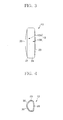
- FIG 1 shows a schematic plan view of a dispenser according to the present embodiment.
- Figure 2 shows a front view thereof.
- a dispenser 10 comprises a case 13 including a trunk portion 11 and a neck portion 12, the trunk portion 11 having an interior space for storing a transfer tape T laminated with a coating film for correction on one side of a band-like sheet or tape and the neck portion 12 being continued to one end side of the trunk portion 11 and formed so as to gradually narrow, as well as a transfer head 14 that is placed on the forward end side of the neck portion 12 and around which the transfer tape T is wound.
- the trunk portion 11 and the neck portion 12 are not distinguished from each other by a distinct boundary such as difference in level.
- a region where an area from a site near the first joints of a thumb, an index finger, and a middle finger to user's fingertips are roughly located, corresponds to the neck portion 12, when the trunk portion 11 is held between the pads of the thumb and the index finger and between the bases of these fingers such that the rear end side of the trunk portion is projected to the back side of a user's hand as described below.
- the case 13 comprises an upper case 13A and a lower case 13B, as shown in Figure 2 .
- the upper case 13A includes an upper wall 20, and an upper peripheral wall 21 continued to an outer periphery of the upper wall 20.
- the lower case 13B includes a lower wall 23, and a lower peripheral wall 24 continued to an outer periphery of the lower wall 23.
- the upper peripheral wall 21 and the lower peripheral wall 24 are fitted to each other to form the case 13.
- the trunk portion 11 has a shape which resembles an elliptical shape, in a planar shape, as shown in Figure 1 .
- the upper wall 20 and the lower wall 23, which form the trunk portion 11, have curved outer peripheral surface shapes, as shown in Figure 3 .
- the neck portion 12 in a general appearance thereof, comprises a side wall portion 25 continued to a peripheral wall of the trunk portion 11 on the upper edge side thereof in Figure 1 , and on the other hand comprises a sloped portion 26 to be curved so as to gradually narrow a width dimension in the vertical direction in Figure 1 of the trunk portion 11 on the lower edge side thereof. Moreover, the neck portion 12 comprises recess portions 28, 28 to be curved toward the upper edge side in Figure 1 and the upper edge side in Figure 2 , respectively. In a lower part side in Figure 2 , the neck portion 12 includes a pair of inclined surfaces 30 in which a center portion thereof is located outward, so that the neck portion 12 is configured to have an outer peripheral surface shape along sides of a substantially triangle in cross-section.
- the transfer head 14 is attached in a state which a tip edge 14A is along a direction perpendicular to a paper surface in Figure 2 .
- the transfer tape T in a roll form stored in the case 13 is guided so as to twist the surface of the tape about 90 degree on the feed path of the tape T, and wound around the transfer head 14.
- the case 13 is one having the following size: the maximum width W1 of about 39 mm in the vertical direction of the trunk portion 11 in Figure 1 and a length L1 of about 62 mm in the horizontal direction of the trunk portion 11 in Figure 1 ; the minimum width W2 of about 15 mm in the vertical direction of the neck portion 12 and a length L2 of about 30 mm in the horizontal direction of the neck portion 12; and the maximum thickness T of about 19 mm in the vertical direction in Figure 2 .
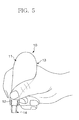
- the trunk portion 11 is held between the pads of a thumb and an index finger and between the bases of these fingers such that the rear end side of the trunk portion 11 is projected to the back side of the user's hand.
- the neck portion 12 is held in place between tip sides of the thumb, the index finger, and a middle finger and about the first joints of these fingers.
- the pad of the tip side of the thumb is in contact with the recess portion 28, while each of the index and the middle fingers is in contact with the inclined surface 30.
- the dispenser 10 is held in the substantially same position as the position in which writing instruments are held.
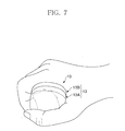
- the tip 14A of the transfer head 14 In the position where the dispenser 10 is held in this manner, the tip 14A of the transfer head 14 is located in a plane generally parallel to the case 13, as shown in Figure 5 . Therefore, in such a position, the tip 14A of the transfer head 14 can be pushed against the paper surface and slid in a direction perpendicular to the paper surface in Figure 5 to transfer the coating film of the transfer tape T onto the surface side of papers.
- Description of structures for feeding and reeling the transfer tape T is omitted because the structures are the substantially same as publicly known structures and are not the gist of the invention.
- the position when the user holds the dispenser 10 with the user's hand is a position similar to a position in which writing instruments are held, so that the user has no feeling of strangeness during its use, as well as can slide the transfer head 14 in its stable position and keep the tip 14A in an easily viewable location. Therefore, this produces an effect that the user can perform a transfer with good precision even when a region to be transferred is a complicated and narrow area.
- the trunk portion 11 has been illustrated and described to have a planar shape which resembles an elliptical shape, the shape of the trunk portion 11 may be modified.
- the trunk portion 11 may be provided in a tubular shape which extends linearly, so as to have an outer peripheral surface shape along sides of a substantially triangle in cross-section.
- the trunk portion 11 may be provided in a tubular shape which gradually narrows the trunk portion 11 toward the forward end, so as to have a similar outer peripheral surface shape in cross-section.
- a formed part having the outer peripheral surface shape along sides of a substantially triangle may be at least provided only on the outer peripheral surface on the forward end side of the trunk portion where the fingertip side is located.
Landscapes
- Adhesive Tape Dispensing Devices (AREA)
Applications Claiming Priority (2)
| Application Number | Priority Date | Filing Date | Title |
|---|---|---|---|
| JP2007253112A JP4899103B2 (ja) | 2007-09-28 | 2007-09-28 | 転着器 |
| PCT/JP2008/066538 WO2009041296A1 (fr) | 2007-09-28 | 2008-09-12 | Dispositif de transfert |
Publications (2)
| Publication Number | Publication Date |
|---|---|
| EP2191978A1 true EP2191978A1 (fr) | 2010-06-02 |
| EP2191978A4 EP2191978A4 (fr) | 2011-11-02 |
Family
ID=40511183
Family Applications (1)
| Application Number | Title | Priority Date | Filing Date |
|---|---|---|---|
| EP08833247A Withdrawn EP2191978A4 (fr) | 2007-09-28 | 2008-09-12 | Dispositif de transfert |
Country Status (5)
| Country | Link |
|---|---|
| US (1) | US20100206488A1 (fr) |
| EP (1) | EP2191978A4 (fr) |
| JP (1) | JP4899103B2 (fr) |
| CA (1) | CA2700439A1 (fr) |
| WO (1) | WO2009041296A1 (fr) |
Families Citing this family (7)
| Publication number | Priority date | Publication date | Assignee | Title |
|---|---|---|---|---|
| US8397784B2 (en) | 2010-08-31 | 2013-03-19 | Sanford, L.P. | Correction tape dispenser with variable clutch mechanism |
| MY152401A (en) * | 2010-09-30 | 2014-09-30 | Widetech Mfg Sdn Bhd | A correction device consisting of an improved body structure |
| MY163858A (en) | 2010-09-30 | 2017-10-31 | Widetech Mfg Sdn Bhd | A tape device |
| US8746313B2 (en) | 2010-12-29 | 2014-06-10 | Sanford, L.P. | Correction tape re-tensioning mechanism and correction tape dispenser comprising same |
| US8578999B2 (en) | 2010-12-29 | 2013-11-12 | Sanford, L.P. | Variable clutch mechanism and correction tape dispenser with variable clutch mechanism |
| US8746316B2 (en) | 2011-12-30 | 2014-06-10 | Sanford, L.P. | Variable clutch mechanism and correction tape dispenser with variable clutch mechanism |
| USD880586S1 (en) * | 2017-12-21 | 2020-04-07 | Tombow Pencil Co., Ltd. | Correction tape dispenser |
Family Cites Families (8)
| Publication number | Priority date | Publication date | Assignee | Title |
|---|---|---|---|---|
| US5499877A (en) * | 1993-04-06 | 1996-03-19 | Fujicopian Co., Ltd. | Transfer ribbon cassette, a case for enclosing the cassette, and a paint film transfer device having the same |
| JP2829699B2 (ja) * | 1993-12-03 | 1998-11-25 | シードゴム工業株式会社 | 塗膜転写具 |
| JP2000025392A (ja) * | 1998-07-08 | 2000-01-25 | Seed Rubber Kogyo Kk | 塗膜転写具用テープカートリッジおよび塗膜転写具 |
| JP2001048414A (ja) * | 1999-08-11 | 2001-02-20 | Tombow Pencil Co Ltd | 塗布具 |
| JP2001180174A (ja) * | 1999-12-27 | 2001-07-03 | Mitsuo Inoue | 筆記具の握り部 |
| US6921223B2 (en) * | 2003-09-15 | 2005-07-26 | Sanford, L.P. | Combo pen |
| US6997229B2 (en) * | 2003-09-16 | 2006-02-14 | Sanford, L.P. | Rotatable applicator tip for a corrective tape dispenser |
| JP2006001236A (ja) | 2004-06-21 | 2006-01-05 | Tombow Pencil Co Ltd | 塗膜転写具 |
-
2007
- 2007-09-28 JP JP2007253112A patent/JP4899103B2/ja active Active
-
2008
- 2008-09-12 CA CA2700439A patent/CA2700439A1/fr not_active Abandoned
- 2008-09-12 EP EP08833247A patent/EP2191978A4/fr not_active Withdrawn
- 2008-09-12 US US12/676,468 patent/US20100206488A1/en not_active Abandoned
- 2008-09-12 WO PCT/JP2008/066538 patent/WO2009041296A1/fr not_active Ceased
Also Published As
| Publication number | Publication date |
|---|---|
| JP2009083177A (ja) | 2009-04-23 |
| JP4899103B2 (ja) | 2012-03-21 |
| US20100206488A1 (en) | 2010-08-19 |
| EP2191978A4 (fr) | 2011-11-02 |
| CA2700439A1 (fr) | 2009-04-02 |
| WO2009041296A1 (fr) | 2009-04-02 |
Similar Documents
| Publication | Publication Date | Title |
|---|---|---|
| EP2191978A1 (fr) | Dispositif de transfert | |
| JP2995659B1 (ja) | 塗膜転写具 | |
| ES2218883T3 (es) | Herramienta para la transferencia de una pelicula de recubrimiento con un cabezal de transferencia. | |
| US20100092228A1 (en) | Writing Instrument Holder and Hand Support | |
| JP4352984B2 (ja) | 転写具 | |
| AU774279B2 (en) | Device for transferring a substance applied to a support tape in the form of a film to a substrate | |
| GB2275042A (en) | Correction tape dispenser | |
| CN216915320U (zh) | 一种带芯易复位的修正头及具有该修正头的修正带 | |
| JP2001162989A (ja) | 塗膜転写用ヘッド装置および塗膜転写具 | |
| JP3157140U (ja) | 携帯型ゲーム機用スクリーン保護シート | |
| JP3753475B2 (ja) | 感圧転写具 | |
| US20050082009A1 (en) | Film transfer device | |
| JP2021512720A5 (fr) | ||
| KR20120021902A (ko) | 깔끔이 수정테이프 점착기 | |
| JP6427185B2 (ja) | 手動式のアプリケーター | |
| JP2016101732A (ja) | 転写具 | |
| JP2004306488A (ja) | 塗膜転写具 | |
| CN114103532B (zh) | 一种易贴合纸面的修正头及具有该修正头的修正带 | |
| JPWO2014203756A1 (ja) | 塗膜転写具 | |
| JP2006290528A (ja) | 転写膜押圧装置および転写具 | |
| JP2020078882A (ja) | 筆記補助具 | |
| KR200400320Y1 (ko) | 보조파지부를 갖는 오기 수정용 테이프 | |
| KR200306930Y1 (ko) | 손가락 장착형 필기구 | |
| KR20170126396A (ko) | 코팅 필름 전사 기구 | |
| JPH04112855U (ja) | 修正テープホルダー |
Legal Events
| Date | Code | Title | Description |
|---|---|---|---|
| PUAI | Public reference made under article 153(3) epc to a published international application that has entered the european phase |
Free format text: ORIGINAL CODE: 0009012 |
|
| 17P | Request for examination filed |
Effective date: 20100215 |
|
| AK | Designated contracting states |
Kind code of ref document: A1 Designated state(s): AT BE BG CH CY CZ DE DK EE ES FI FR GB GR HR HU IE IS IT LI LT LU LV MC MT NL NO PL PT RO SE SI SK TR |
|
| AX | Request for extension of the european patent |
Extension state: AL BA MK RS |
|
| DAX | Request for extension of the european patent (deleted) | ||
| A4 | Supplementary search report drawn up and despatched |
Effective date: 20111004 |
|
| RIC1 | Information provided on ipc code assigned before grant |
Ipc: B65H 37/00 20060101ALI20110927BHEP Ipc: B43M 11/06 20060101ALI20110927BHEP Ipc: B43L 19/00 20060101AFI20110927BHEP |
|
| STAA | Information on the status of an ep patent application or granted ep patent |
Free format text: STATUS: THE APPLICATION IS DEEMED TO BE WITHDRAWN |
|
| 18D | Application deemed to be withdrawn |
Effective date: 20120503 |