EP2192206A1 - Précipitation à nanocarbure renforcée par des aciers structurels, résistant à la corrosion et à résistance ultra forte - Google Patents
Précipitation à nanocarbure renforcée par des aciers structurels, résistant à la corrosion et à résistance ultra forte Download PDFInfo
- Publication number
- EP2192206A1 EP2192206A1 EP10151840A EP10151840A EP2192206A1 EP 2192206 A1 EP2192206 A1 EP 2192206A1 EP 10151840 A EP10151840 A EP 10151840A EP 10151840 A EP10151840 A EP 10151840A EP 2192206 A1 EP2192206 A1 EP 2192206A1
- Authority
- EP
- European Patent Office
- Prior art keywords
- less
- alloy
- paragraph
- ksi
- steel alloy
- Prior art date
- Legal status (The legal status is an assumption and is not a legal conclusion. Google has not performed a legal analysis and makes no representation as to the accuracy of the status listed.)
- Granted
Links
Images



Classifications
-
- C—CHEMISTRY; METALLURGY
- C22—METALLURGY; FERROUS OR NON-FERROUS ALLOYS; TREATMENT OF ALLOYS OR NON-FERROUS METALS
- C22C—ALLOYS
- C22C38/00—Ferrous alloys, e.g. steel alloys
- C22C38/18—Ferrous alloys, e.g. steel alloys containing chromium
- C22C38/40—Ferrous alloys, e.g. steel alloys containing chromium with nickel
- C22C38/44—Ferrous alloys, e.g. steel alloys containing chromium with nickel with molybdenum or tungsten
-
- C—CHEMISTRY; METALLURGY
- C21—METALLURGY OF IRON
- C21D—MODIFYING THE PHYSICAL STRUCTURE OF FERROUS METALS; GENERAL DEVICES FOR HEAT TREATMENT OF FERROUS OR NON-FERROUS METALS OR ALLOYS; MAKING METAL MALLEABLE, e.g. BY DECARBURISATION OR TEMPERING
- C21D6/00—Heat treatment of ferrous alloys
- C21D6/02—Hardening by precipitation
-
- C—CHEMISTRY; METALLURGY
- C21—METALLURGY OF IRON
- C21D—MODIFYING THE PHYSICAL STRUCTURE OF FERROUS METALS; GENERAL DEVICES FOR HEAT TREATMENT OF FERROUS OR NON-FERROUS METALS OR ALLOYS; MAKING METAL MALLEABLE, e.g. BY DECARBURISATION OR TEMPERING
- C21D6/00—Heat treatment of ferrous alloys
- C21D6/04—Hardening by cooling below 0 degrees Celsius
-
- C—CHEMISTRY; METALLURGY
- C22—METALLURGY; FERROUS OR NON-FERROUS ALLOYS; TREATMENT OF ALLOYS OR NON-FERROUS METALS
- C22C—ALLOYS
- C22C38/00—Ferrous alloys, e.g. steel alloys
- C22C38/18—Ferrous alloys, e.g. steel alloys containing chromium
- C22C38/40—Ferrous alloys, e.g. steel alloys containing chromium with nickel
- C22C38/46—Ferrous alloys, e.g. steel alloys containing chromium with nickel with vanadium
-
- C—CHEMISTRY; METALLURGY
- C22—METALLURGY; FERROUS OR NON-FERROUS ALLOYS; TREATMENT OF ALLOYS OR NON-FERROUS METALS
- C22C—ALLOYS
- C22C38/00—Ferrous alloys, e.g. steel alloys
- C22C38/18—Ferrous alloys, e.g. steel alloys containing chromium
- C22C38/40—Ferrous alloys, e.g. steel alloys containing chromium with nickel
- C22C38/50—Ferrous alloys, e.g. steel alloys containing chromium with nickel with titanium or zirconium
-
- C—CHEMISTRY; METALLURGY
- C22—METALLURGY; FERROUS OR NON-FERROUS ALLOYS; TREATMENT OF ALLOYS OR NON-FERROUS METALS
- C22C—ALLOYS
- C22C38/00—Ferrous alloys, e.g. steel alloys
- C22C38/18—Ferrous alloys, e.g. steel alloys containing chromium
- C22C38/40—Ferrous alloys, e.g. steel alloys containing chromium with nickel
- C22C38/52—Ferrous alloys, e.g. steel alloys containing chromium with nickel with cobalt
Definitions
- the present invention relates to cobalt, nickel, chromium stainless martensitic steel alloys having ultrahigh strength and corrosion resistance characterized by nanoscale sized carbide precipitates, in particular, M 2 C precipitates.
- ultrahigh-strength steels Main structural components in aerospace and other high-performance structures are almost exclusively made of ultrahigh-strength steels because the weight, size and, in some cases, cost penalties associated with use of other materials is prohibitive.
- ultrahigh-strength steels with a tensile strength in the range of at least 240 ksi to 300 ksi have poor general corrosion resistance and are susceptible to hydrogen and environmental embrittlement.
- cadmium plating of the components is typically employed, and when wear resistance is needed, hard chromium plating is predominantly used.
- These coatings have disadvantages from a cost, manufacturing, environmental and reliability standpoint. Consequently, a goal in the design or discovery of ultrahigh-strength steel alloys is elimination of the need for cadmium and chromium coatings without a mechanical deficit or diminishment of strength.
- One performance objective for alloys of the subject invention is replacement of non-stainless structural steels with stainless or corrosion resistant steels that have tensile strengths greater than about 240 ksi, that do not require cadmium coating and which demonstrate wear resistance without chromium plating or other protective and wear resistant coatings.
- 300M steel is 300M steel.
- This alloy is essentially 4340 steel modified to provide a slightly higher Stage I tempering temperature, thereby allowing the bakeout of embrittling hydrogen introduced during processing.
- Aerospace Material Specification AMS 6257A [SAE International, Warrendale, PA, 2001], which is incorporated herewith, covers a majority of the use of 300M steel in aerospace applications.
- minimum tensile properties are 280 ksi ultimate tensile strength (UTS), 230 ksi yield strength (YS), 8% elongation and a reduction of area of 30%.
- the average plane strain mode I fracture toughness is 52 ksi in [ Philip, T. V. and T. J.
- the high tensile strength of 300M steel allows the design of lightweight structural components in aerospace systems such as landing gear.
- the lack of general corrosion resistance requires cadmium coating, and the low stress corrosion cracking resistance results in significant field failures due to environmental embrittlement.
- Precipitation hardening stainless steels primarily 15-5PH, [AMS 5659K, SAE International, Warrendale, PA, 1998], which is incorporated herewith, may also be used in structural aerospace components, but typically only in lightly loaded applications where the weight penalties due to its low strength are not large. Corrosion resistance is sufficient for such an alloy so that cadmium plating can be eliminated; however minimum tensile properties of 15-5PH in the maximum strength H900 condition are only 190 ksi UTS and 170 ksi YS. This limits the application to components that are not strength limited.
- Carpenter Custom 465TM steel Another precipitation strengthening stainless steel, Carpenter Custom 465TM steel [Alloy Digest, SS-716, Materials Park, OH, ASM International, 1998], which is incorporated herewith, uses intermetallic precipitation and reaches a maximum UTS of slightly below 270 ksi. At that strength level Custom 465TM steel has a low Charpy V-notch impact energy of about 5 ft-lb [ Kimmel, W. M., N. S. Kuhn, et al., Cryogenic Model Materials, 39th AIAA Aerospace Sciences Meeting & Exhibit, Reno, NV, 2001 ], which is incorporated herewith. For most structural applications Custom 465TM steel must be used in a condition that limits its UTS to well below 270 ksi in order to maintain adequate Charpy V-notch impact resistance.
- a number of secondary hardening stainless steels have been developed that reach ultimate strength levels of up to 270 ksi. These are disclosed in U.S. Patent Nos. Re. 26,225, 3,756,808 , 3,873,378 , and 5,358,577 . These stainless steels use higher chromium levels to maintain corrosion resistance and therefore compromise strength.
- a primary feature of these alloys is the large amount of austenite, both retained and formed during secondary hardening. The austenite modifies the flow behavior of the alloys and, while they may achieve an UTS as high as 270 ksi, their yield strength is no more than 200 ksi. This large gap between yield and ultimate limits the applications for which these steels can be used. Thus there has remained the need for ultrahigh strength, noncorrosive steel alloys that have a yield strength of at least about 230 ksi and an ultimate tensile strength of at least about 280 ksi.
- the invention comprises stainless steel alloys comprising, by weight, about: 0.1 to 0.3% carbon (C), 8 to 17% cobalt (Co), less than 10% nickel (Ni), greater than 6% and less than 11% chromium (Cr), and less than 3% molybdenum (Mo) along with other elemental additives including minor amounts of Si, Cu, Mn, Nb, V, Ta, W, Ti, Zr, rare earths and B, the remainder iron (Fe) and incidental elements and impurities, processed so as to be principally in the martensitic phase with ultrahigh strength and noncorrosive physical characteristics as a result of the choice and amount of constituents and the processing protocol.
- C carbon
- Co cobalt
- Ni nickel
- Cr chromium
- Mo molybdenum
- the alloys of the subject invention can achieve an ultimate tensile strength (UTS) of about 300 ksi with a yield strength (YS) of about 230 ksi and also provide corrosion resistance with greater than about 6% and less than about 11 %, preferably less than about 10% by weight chromium.
- the alloys of the invention provide a combination of the observed mechanical properties of structural steels, that are currently cadmium coated and used in aerospace applications, and the corrosion properties of stainless steels without special coating or plating.
- Highly efficient nanoscale carbide (M 2 C) strengthening of the described alloys provides ultrahigh strengths with lower carbon and alloy content while improving corrosion resistance due to the ability of the nanoscale carbides to oxidize and supply chromium as a passivating oxide film.
- a further object of the invention is to provide ultrahigh-strength, corrosion resistant, structural steel alloys that do not require plating or coating to resist corrosion.
- Another object of the invention is to provide ultrahigh-strength, corrosion resistant, structural steel alloys having cobalt, nickel and chromium alloying elements in combination with other elements whereby the alloys are corrosion resistant.
- a further object of the invention is to provide ultrahigh-strength, corrosion resistant, structural steel alloys having an ultimate tensile strength (UTS) greater than about 240 ksi and preferably greater than about 280 ksi, and a yield strength (YS) greater than about 200 ksi and preferably greater than about 230 ksi.
- UTS ultimate tensile strength
- YS yield strength
- Another object of the invention is to provide ultrahigh-strength, corrosion resistant, structural steel alloys characterized by a lath martensitic microstructure and by M 2 C nanoscale sized precipitates in the grain structure and wherein other M X C precipitates where x > 2 have generally been solubilized.
- Yet another object of the invention is to provide ultrahigh-strength, corrosion resistant, structural steel alloys which may be easily worked to form component parts and articles while maintaining its ultrahigh strength and noncorrosive characteristics.
- a further obj ect of the invention is to provide processing protocols for the disclosed stainless steel alloy compositions that enable creation of an alloy microstructure having highly desirable strength and noncorrosive characteristics.
- FIG. 1 is a system flow-block diagram which illustrates the processing/structure/properties/performance relationships for alloys of the invention.
- the desired performance for the application e.g. aerospace structures, landing gear, sports equipment, tools, etc.
- Alloys of the invention exhibit the structural characteristics that can achieve the desired combination of properties and can be assessed through the sequential processing steps shown on the left of FIG. 1 .
- the criteria for the physical properties and the processing capabilities or characteristics for the alloys This is followed by a description of the analytical and experimental techniques relating to the discovery and examples of the alloys that define, in general, the range and extent of the elements, physical characteristics and processing features of the present invention.
- a principal goal of the subject invention is to provide alloys with the objective physical properties recited above and with processability that renders the alloys useful and practical. With a number of possible processing paths associated with the scale of manufacture and the resulting cleanliness and quality for a given application, compatibility of the alloys of the subject invention with a wide range of processes is desirable and is thus a feature of the invention.
- a primary objective for and characteristic of the alloys is compatibility with melting practices such as Vacuum Induction Melting (VIM), Vacuum Arc Remelting (VAR), and Electro-Slag Remelting (ESR) and other variants such as Vacuum Electro-Slag Remelting (VSR).
- Alloys of the subject invention can also be produced by other processes such as air melting and powder metallurgy. Of importance is the behavior of the alloys to exhibit limited solidification microsegregation under the solidification conditions of the above processes. By selection of appropriate elemental content in the alloys of the subject invention, the variation of composition that results from solidification during processing across a secondary dendrite can be minimized.
- Alloys of the subject invention also possess reasonable hot ductility such that hot working after homogenization can be accomplished within temperature and reduction constraints typical of current industrial practice.
- Typical hot working practice for alloys of the subject invention should enable cross-sectional reduction ratios in excess of three to one and preferably in excess of five to one.
- initial hot working of the ingot should be possible below 1100°C, and finish hot working to the desired product size should be possible at temperatures below 950°C.
- Objectives regarding solution heat treatment include the goal to fully dissolve all primary alloy carbides (i.e. M X C where X > 2) while maintaining a fine scale grain refining dispersion (i.e. MC) and a small grain size, generally equal to or smaller than ASTM grain size number 5 in accordance with ASTM E112 [ASTM, ASTM E112-96, West Conshohocken, PA, 1996] which is incorporated herewith.
- MC fine scale grain refining dispersion
- ASTM E112 ASTM E112
- alloys of the invention With alloys of the invention, such grain coarsening is slowed by MC precipitates that pin the grain boundaries and, as solution heat treatment temperature increases, the amount of this grain refining dispersion needed to avoid or reduce grain coarsening increases.
- Alloys of the subject invention generally thoroughly dissolve all coarse scale carbides, i.e. M X C where x > 2, while maintaining an efficient grain refining dispersion at reasonable solution heat treatment temperatures in the range of 850°C to 1100°C, preferably 950°C to 1050°C.
- Alloys of the subject invention are generally, fully martensitic after cooling or quenching at moderate rates in section sizes less than three inches and preferably less than six inches when cooled to cryogenic temperatures, or preferably to room temperature.
- components manufactured using alloys of the subject invention may be tempered in a temperature range and for a period of time in which the carbon in the alloy will form coherent nanoscale M 2 C carbides while avoiding the formation of other carbide products, i.e. M 2 C where x>2.
- the component is heated to the process temperature at a rate determined by the power of the furnace and the size of the component section and held for a reasonable time, then cooled or quenched to room temperature.
- the tempering process may be divided into multiple steps where each tempering step is followed by a cool or quench to room temperature and preferably a subsequent cool to cryogenic temperatures to form martensite.
- the temperature of the temper process would typically be between 200°C to 600°C, preferably 450°C to 540°C and be less than twenty-four hours in duration, preferably between two to ten hours.
- the outcome of the desired process is a martensitic matrix (generally free of austenite) strengthened by a nanoscale M 2 C carbide dispersion, devoid of transient cementite that forms during the early stages of the process, and without other alloy carbides that may precipitate if the process time becomes too long.
- a significant feature of alloys of the invention is related to the high tempering temperatures used to achieve its secondary hardening response. Although a specific goal is to avoid cadmium plating for corrosion resistance, many components made from an alloy of the invention may require an electroplating process such as nickel or chromium during manufacture or overhaul. Electroplating processes introduce hydrogen into the microstructure that can lead to embrittlement and must be baked out by exposing the part to elevated temperatures after plating. Alloys of the invention can be baked at temperatures nearly as high as their original tempering temperature without reducing the strength of the alloy. Since tempering temperatures are significantly higher in alloys of the invention compared to commonly used 4340 and 300M alloys, the bake-out process can be accomplished more quickly and reliably.
- Certain surface modification techniques for wear resistance, corrosion resistance, and decoration such as physical vapor deposition (PVD), or surface hardening techniques such as gas or plasma nitriding, are optimally performed at temperatures on the order of 500°C and for periods on the order of hours.
- PVD physical vapor deposition
- surface hardening techniques such as gas or plasma nitriding
- alloys of the subject invention are typically manufactured or machined before solution heat treatment and aging.
- the manufacturing and machining operations require a material that is soft and exhibits favorable chip formation as material is removed. Therefore alloys of the subject invention are preferably annealed after the hot working process before they are supplied to a manufacturer.
- the goal of the annealing process is to reduce the hardness of an alloy of the subject invention without promoting excessive austenite.
- annealing would be accomplished by heating the alloy in the range of 600°C to 850°C, preferably in the range 700°C to 750°C for a period less than twenty-four hours, preferably between two and eight hours and cooling slowly to room temperature.
- a multiple-step annealing process may provide more optimal results.
- an alloy of the invention may be annealed at a series of temperatures for various times that may or may not be separated by an intermediate cooling step or steps.
- a component made of an alloy of the subject invention may require a grinding step to maintain the desired final dimensions of the part. Grinding of the surface removes material from the part by abrasive action against a high-speed ceramic wheel. Damage to the component by overheating of the surface of the part and damage to the grinding wheel by adhesion of material needs to be avoided. These complications can be avoided primarily by lowering the retained austenite content in the alloy. For this and the other reasons stated above, alloys of the subject invention exhibit very little retained austenite after solution heat treatment.
- alloys of the subject invention may require joining by various welding process such as gas-arc welding, submerged-arc welding, friction-stir welding, electron-beam welding and others. These processes require the material that is solidified in the fusion zone or in the heat-affected zone of the weld to be ductile after processing. Pre-heat and post-heat may be used to control the thermal history experienced by the alloy within the weld and in the heat-affected zone to promote weld ductility. A primary driver for ductile welds is lower carbon content in the material, however this also limits strength. Alloys of the subject invention achieve their strength using very efficient nanoscale M 2 C carbides and therefore can achieve a given level of strength with lower carbon content than steels such as 300M steel, consequently promoting weldability.
- the alloy designs achieve required corrosion resistance with a minimum Cr content because high Cr content limits other desired properties in several ways.
- one result of higher Cr is the lowering of the martensite M s temperature which, in turn, limits the content of other desired alloying elements such as Ni.
- High Cr levels also promote excessive solidification microsegregation that is difficult to eliminate with high-temperature homogenization treatments.
- High Cr also limits the high-temperature solubility of C required for carbide precipitation strengthening, causing use of high solution heat treatment temperatures for which grain-size control becomes difficult.
- a feature of the alloys of the invention is utilization of Cr in the range of greater than about 6% and less than about 11 % (preferably less than about 10%) by weight in combination with other elements as described to achieve corrosion resistance with structural strength.
- Another feature of the alloys is to achieve the required carbide strengthening with a minimum carbon content. Like Cr, C strongly lowers M s temperatures and raises solution temperatures. High C content also limits weldability, and can cause corrosion problems associated with Cr carbide precipitation at grain boundaries. High C also limits the extent of softening that can be achieved by annealing to enhance machinability.
- Co both of the primary features just discussed are enhanced by the use of Co.
- the thermodynamic interaction of Co and Cr enhances the partitioning of Cr to the oxide film formed during corrosion passivation, thus providing corrosion protection equivalent to a higher Cr steel.
- Co also catalyzes carbide precipitation during tempering through enhancement of the precipitation thermodynamic driving force, and by retarding dislocation recovery to promote heterogeneous nucleation of carbides on dislocations.
- C in the range of about 0.1% to 0.3% by weight combined with Co in the range of about 8% to 17% by weight along with Cr as described, and the other minor constituent elements, provides alloys with corrosion resistance and ultrahigh strength.
- the desired combination of corrosion resistance and ultrahigh strength is also promoted by refinement of the carbide strengthening dispersion down to the nanostructural level, i.e., less than about ten nanometers in diameter and preferably less than about five nanometers.
- the relatively high shear modulus of the M 2 C alloy carbide decreases the optimal particle size for strengthening down to a diameter of only about three nanometers. Refining the carbide precipitate size to this level provides a highly efficient strengthening dispersion. This is achieved by obtaining a sufficiently high thermodynamic driving force through alloying.
- This refinement provides the additional benefit of bringing the carbides to the same length scale as the passive oxide film so that the Cr in the carbides can participate in film formation.
- the carbide formation does not significantly reduce corrosion resistance.
- a further benefit of the nanoscale carbide dispersion is effective hydrogen trapping at the carbide interfaces to enhance stress corrosion cracking resistance.
- the efficient nanoscale carbide strengthening also makes the system well suited for surface hardening by nitriding during tempering to produce M 2 (C,N) carbonitrides of the same size scale for additional efficient strengthening without significant loss of corrosion resistance. Such nitriding can achieve surface hardness as high as 1100 Vickers Hardness (VHN) corresponding to 70 HRC.
- Toughness is further enhanced through grain refinement by optimal dispersions of grain refining MC carbide dispersions that maintain grain pinning during normalization and solution treatments and resist microvoid nucleation during ductile fracture.
- Melt deoxidation practice is controlled to favor formation of Ti-rich MC dispersions for this purpose, as well as to minimize the number density of oxide and oxysulfide inclusion particles that form primary voids during fracture.
- the amount of MC determined by mass balance from the available Ti content, accounts for less than 10% of the alloy C content. Increasing Ni content within the constraints of the other requirements enhances resistance to brittle fracture.
- M 2 C particle size through precipitation driving force control allows ultrahigh strength to be maintained at the completion of M 2 C precipitation in order to fully dissolve Fe 3 C cementite carbides that precipitate prior to M 2 C and limit fracture toughness through microvoid nucleation.
- the cementite dissolution is considered effectively complete when M 2 C accounts for 85% of the alloy C content, as assessed by the measured M 2 C phase fraction using techniques described by Montgomery [ Montgomery, J. S. and G. B. Olson, M2C Carbide Precipitation in AF1410, Gilbert R. Speich Symposium: Fundamentals of Aging and Tempering in Bainitic and Martensitic Steel Products, ISS-AIME, Warrendale, PA, 177-214, 1992 ], which is incorporated herewith.
- thermodynamic driving force for their formation.
- other phases that can limit toughness such as other carbides (e.g. M 23 C 6 , M 6 C and M 7 C 3 ) and topologically close packed (TCP) intermetallic phases (e.g. ⁇ and ⁇ phases) is avoided by constraining the thermodynamic driving force for their formation.
- carbides e.g. M 23 C 6 , M 6 C and M 7 C 3
- TCP topologically close packed
- resistance to hydrogen stress-corrosion is further enhanced by controlling segregation of impurities and alloying elements to prior-austenite grain boundaries to resist hydrogen-assisted intergranular fracture. This is promoted by controlling the content of undesirable impurities such as P and S to low levels and gettering their residual amounts in the alloy into stable compounds such as La 2 O 2 S or Ce 2 O 2 S.
- Boundary cohesion is further enhanced by deliberate segregation of cohesion enhancing elements such as B, Mo and W during heat treatment. These factors promoting stress corrosion cracking resistance will also enhance resistance to corrosion fatigue.
- Martensite Ms temperatures measured by quenching dilatometry and 1% transformation fraction, are also maintained sufficiently high to establish a lath martensite microstructure and minimize the content of retained austenite which can otherwise limit yield strength.
- the alloys can be produced via various process paths such as for example casting, powder metallurgy or ingot metallurgy.
- the alloy constituents can be melted using any conventional melt process such as air melting but more preferably by vacuum induction melting (VIM).
- VIM vacuum induction melting
- the alloy can thereafter be homogenized and hot worked, but a secondary melting process such as electro slag remelting (ESR) or vacuum arc remelting (VAR) is preferred in order to achieve improved fracture toughness and fatigue properties.
- ESR electro slag remelting
- VAR vacuum arc remelting
- additional remelting operations can be utilized prior to homogenization and hot working.
- the alloy is initially formed by combination of the constituents in a melt process.
- the alloy may then be homogenized prior to hot working or it may be heated and directly hot worked. If homogenization is used, it may be carried out by heating the alloy to a metal temperature in the range of about 1100°C or 1110°C or 1120°C to 1330°C or 1340°C or 1350°C or, possibly as much as 1400°C for a period of time of at least four hours to dissolve soluble elements and carbides and to also homogenize the structure.
- One of the design criteria for the alloy is low microsegregation, and therefore the time required for homogenization of the alloy is typically shorter than other stainless steel alloys.
- a suitable time is six hours or more in the homogenization metal temperature range. Normally, the soak time at the homogenization temperature does not have to extend for more than seventy-two hours. Twelve to eighteen hours in the homogenization temperature range has been found to be quite suitable.
- a typical homogenization metal temperature is about 1240°C.
- the alloy After homogenization the alloy is typically hot worked.
- the alloy can be hot worked by, but not limited to, hot rolling, hot forging or hot extrusion or any combinations thereof. It is common to initiate hot working immediately after the homogenization treatment in order to take advantage of the heat already in the alloy. It is important that the finish hot working metal temperature is substantially below the starting hot working metal temperature in order to assure grain refinement of the structure through precipitation of MC carbides.
- the alloy is typically reheated for continued hot working to the final desired size and shape.
- the reheating metal temperature range is about 950°C or 960°C or 970°C to 1230°C or 1240°C or 1250°C or possibly as much as 1300°C with the preferred range being about 1000°C or 1010°C to 1150°C or 1160°C.
- the reheating metal temperature is near or above the solvus temperature for MC carbides, and the objective is to dissolve or partially dissolve soluble constituents that remain from casting or may have precipitated during the preceding hot working. This reheating step minimizes or avoids primary and secondary phase particles and improves fatigue crack growth resistance and fracture toughness.
- the reheating metal temperature range is about 840°C or 850°C or 860°C to 1080°C or 1090°C or 1100°C or possibly as much as 1200°C with the preferred range being about 950°C or 960°C to 1000°C or 1010°C.
- the lower reheating metal temperature for smaller cross-sections is below the solvus temperature for other (non-MC) carbides, and the objective is to minimize or prevent their coarsening during reheating so that they can quickly be dissolved during the subsequent normalizing or solution heat treatment.
- Final mill product forms such as, for example, bar stock and forging stock are typically normalized and/or annealed prior to shipment to customers.
- the normalizing metal temperature range is about 880°C or 890°C or 900°C to 1080°C or 1090°C or 1100°C with the preferred range being about 1020°C to 1030°C or 1040°C.
- a suitable time is one hour or more and typically the soak time at the normalizing temperature does not have to extend for more than three hours.
- the alloy is thereafter cooled to room temperature.
- the alloy After normalizing the alloy is typically annealed to a suitable hardness or strength level for subsequent customer processing such as, for example, machining. During annealing the alloy is heated to a metal temperature range of about 600°C or 610°C to 840°C or 850°C, preferably between 700°C to 750°C for a period of at least one hour to coarsen all carbides except the MC carbide. A suitable time is two hours or more and typically the soak time at the annealing temperature does not have to extend for more than twenty-four hours.
- solution heat treatment preferably in the metal temperature range of about 850°C or 860°C to 1090°C or 1100°C, more preferably about 950°C to 1040°C or 1050°C for a period of three hours or less.
- a typical time for solution heat treatment is one hour.
- the solution heat treatment metal temperature is above the solvus temperature for all carbides except MC carbides, and the objective is to dissolve soluble constituents that may have precipitated during the preceding processing. This inhibits grain growth while enhancing strength, fracture toughness and fatigue resistance.
- the alloy After quenching to room temperature the alloy may be subjected to a cryogenic treatment or it may be heated directly to the tempering temperature.
- the cryogenic treatment promotes a more complete transformation of the microstructure to a lath martensitic structure. If a cryogenic treatment is used, it is carried out preferably below about -70°C. A more preferred cryogenic treatment would be below about -195°C.
- a typical cryogenic treatment is in the metal temperature range of about -60°C or -70°C to -85°C or -95°C.
- Another typical cryogenic treatment is in the metal temperature range of about -180°C or -190°C to -220°C or -230°C. Normally, the soak time at the cryogenic temperature does not have to extend for more than ten hours. A typical time for cryogenic treatment is one hour.
- the alloy is tempered at intermediate metal temperatures.
- the tempering treatment is preferably in the metal temperature range of about 200°C or 210°C or 220°C to 580°C or 590°C or 600°C, more preferably about 450°C to 530°C or 540°C.
- the soak time at the tempering temperature does not have to extend for more than twenty-four hours. Two to ten hours in the tempering temperature range has been found to be quite suitable.
- precipitation of nanoscale M 2 C-strengthening particles increases the thermal stability of the alloy, and various combinations of strength and fracture toughness can be achieved by using different combinations of temperature and time.
- Multi-step treatments consist of additional cycles of cryogenic treatments followed by thermal treatments as outlined in the text above.
- One additional cycle might be beneficial but multiple cycles are typically more beneficial.
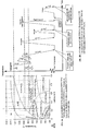
- FIGS. 2A and 2B An example of the relationship between the processing path and the phase stability in a particular alloy of the invention is depicted in FIGS. 2A and 2B .
- FIG. 2A depicts the equilibrium phases of alloy 2C of the invention wherein the carbon content is 0.23% by weight as shown in TABLE 1.
- FIG. 2B then discloses the processing sequence employed with respect to the described alloy 2C.
- the alloy is homogenized at a metal temperature exceeding the single phase (fcc) equilibrium temperature of about 1220°C. All carbides are solubilized at this temperature.
- Forging to define a desired billet, rod or other shape results in cooling into a range where various complex carbides may form.
- the forging step may be repeated by reheating at least to the metal temperature range (980°C to 1220°C) where only MC carbides are at equilibrium.
- Subsequent cooling will generally result in retention of primarily MC carbides, other primary alloy carbides such as M 7 C 3 and M 23 C 6 and the formation of generally a martensitic matrix.
- Normalization in the same metal temperature range followed by cooling dissolves the M 7 C 3 and M 23 C 6 primary carbides while preserving the MC carbides.
- Annealing in the metal temperature range 600°C or 610°C to 840°C or 850°C and cooling reduces the hardness level to a reasonable value for machining.
- the annealing process softens the martensite by precipitating carbon into alloy carbides that are too large to significantly strengthen the alloy yet are small enough to be readily dissolved during later solution treatment. This process is followed by delivery of the alloy product to a customer for final manufacture of a component part and appropriate heat treating and finishing.
- the customer will form the alloy into a desired shape. This will be followed by solution heat treatment in the MC carbide temperature range and then subsequent rapid quenching to maintain or form the desired martensitic structure. Tempering and cooling as previously described may then be employed to obtain strength and fracture toughness as desired.
- a series of prototype alloys were prepared.
- the melt practice for the refining process was selected to be a double vacuum melt with La and Ce impurity gettering additions.
- Substitutional grain boundary cohesion enhancers such as W and Re were not considered in the making of the first prototype, but an addition of twenty parts per million B was included for this purpose.
- Ti was added as a deoxidation agent, promoting TiC particles to pin the grain boundaries and reduce grain growth during solution treatment prior to tempering.
- the major alloying elements in the first prototype are C, Mo, and V (M 2 C carbide formers), Cr (M 2 C carbide former and oxide passive film former), and Co and Ni (for various required matrix properties).
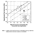
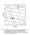
- the exact alloy composition and material processing parameters were determined by an overall design synthesis considering the linkages and a suite of computational models described elsewhere [ Olson, G. B, "Computational Design of Hierarchically Structured Materials.”, Science 277, 1237-1242, 1997 ], which is incorporated herewith. The following is a summary of the initial prototype procedure. Selected parameters are indicated in FIGS. 3-6 by a star ( ⁇ ).
- the amount of Cr was determined by the corrosion resistance requirement and a passivation thermodynamic model developed by Campbell [ Campbell, C, Systems Design of High Performance Stainless Steels, Materials Science and Engineering, Evanston, IL, Northwestern 243, 1997 ], which is incorporated herewith.
- the amount of C was determined by the strength requirement and an M2C precipitation/strengthening model according to the correlation illustrated in FIG. 3 . Based on the goal of achieving 53 HRC hardness, a C content of 0.14% by weight was selected.
- the tempering temperature and the amounts of M2C carbide formers Mo and V were determined to meet the strength requirement with adequate M2C precipitation kinetics, maintain a 1000°C solution treatment temperature, and avoid microsegregation.
- Amounts of Co and Ni were determined to (1) maintain a martensite start temperature of at least 200°C, using a model calibrated to Ms temperatures measured by quenching dilatometry and 1% transformation fraction, so a lath martensite matrix structure can be achieved after quenching, (2) maintain a high M2C carbide initial driving force for efficient strengthening, (3) improve the bcc cleavage resistance by maximizing the Ni content, and (4) maintain the Co content above 8% by weight to achieve sufficient dislocation recovery resistance to enhance M 2 C nucleation and increase Cr partitioning to the oxide film by increasing the matrix Cr activity.
- composition of the first design prototype designated 1 is given in TABLE 1 along with later design iterations.
- the initial design included the following processing parameters:
- a fifth series of alloys designated 5B through 5F in TABLE 1, examined the limits of Ni that can be added to the alloy to improve fracture toughness by lowering the ductile to brittle transition temperature. While the alloy M s for these compositions falls below room temperature as the NI content reaches to about 10 percent by weight, it was found that tempering the alloy in multiple steps with cryogenic cooling between each step was able to convert the majority of the retained austenite to martensite. This allows good strength properties to be achieved in combination with high Ni content to control ductile fracture behavior even in alloys that are fully austenitic after quenching. Although multiple tempering has been commonly used to minimize retained austenite in steels, it was unexpected that the technique could be used effectively in alloys with such high Ni contents and high austenite contents.
- the sixth series of alloys designated 6A through 6M in TABLE 1, was determined to incorporate the features represented in the first five series and are considered preferred embodiments of the invention. Thus, appropriate processing of the described alloys provides an essentially martensitic phase.
- Alloy 1 in TABLE 1 was vacuum induction melted (VIM) to a six inch diameter electrode which was subsequently vacuum arc remelted (VAR) to a eight inch diameter ingot.
- VIM vacuum induction melted
- VAR vacuum arc remelted
- the material was homogenized for seventy-two hours at 1200°C, forged and annealed according to the preferred processing techniques described above and depicted in FIG 2A and 2B . Dilatometer samples were machined and the M s temperature was measured as 175°C by quenching dilatometry and 1% transformation fraction.
- Alloy 2A in TABLE 1 was vacuum induction melted (VIM) to a six inch diameter electrode which was subsequently vacuum arc remelted (VAR) to a eight inch diameter ingot.
- VIM vacuum induction melted
- VAR vacuum arc remelted
- the ingot was homogenized for twelve hours at 1190°C, forged and rolled to 1.500 inch square bar starting at 1120°C, and annealed according to the preferred processing techniques described above and depicted in FIG 2A and 2B .
- Dilatometer samples were machined and the M s temperature was measured as 265°C by quenching dilatometry and 1% transformation fraction.
- Test samples were machined from the square bar, solution heat treated at 1050°C for one hour, oil quenched, immersed in liquid nitrogen for one hour, warmed to room temperature, tempered at 500°C for five hours, air cooled, immersed in liquid nitrogen for one hour, warmed to room temperature and tempered at 500°C for five and one-half hours.
- the measured properties are listed in TABLE 3 below.
- the reference to the corrosion rate of 15-5PH (H900 condition) was made using a sample tested under identical conditions.
- the average corrosion rate for 15-5PH (H900 condition) for this test was 0.26 mils per year (mpy).
- Alloy 2B in TABLE 1 was vacuum induction melted (VIM) to a six inch diameter electrode which was subsequently vacuum arc remelted (VAR) to a eight inch diameter ingot.
- VIM vacuum induction melted
- VAR vacuum arc remelted
- the ingot was homogenized for twelve hours at 1190°C, forged and rolled to 1.000 inch diameter round bar starting at 1120°C and annealed according to the preferred processing techniques described above and depicted in FIG 2A and 2B .
- Dilatometer samples were machined and the M s temperature was measured as 225°C by quenching dilatometry and 1% transformation fraction.
- Alloy 2C in TABLE 1 was vacuum induction melted (VIM) to a six inch diameter electrode which was subsequently vacuum arc remelted (VAR) to a eight inch diameter ingot.
- VIM vacuum induction melted
- VAR vacuum arc remelted
- the ingot was homogenized for twelve hours at 1190°C, forged to 2.250 inch square bar starting at 1120°C and annealed according to the preferred processing techniques described above and depicted in FIG 2A and 2B .
- Dilatometer samples were machined and the M s temperature was measured as 253°C by quenching dilatometry and 1% transformation fraction.
- Test samples were machined from the square bar, solution heat treated at 1025°C for 75 minutes, oil quenched, immersed in liquid nitrogen for one hour, warmed to room temperature, tempered at 498°C for eight hours. The measured properties are listed in TABLE 6 below. TABLE 6 Various measured properties for Alloy 2C Property Value Yield Strength 221 ksi Ultimate Tensile Strength 297 ksi Elongation 12.5% Reduction of Area 58% Hardness 55 HRC K I c Fracture Toughness 42 ksi ⁇ in
- Test samples were machined from the square bar, solution heat treated at 1025°C for 75 minutes, oil quenched, immersed in liquid nitrogen for one hour, warmed to room temperature, tempered at 498°C for twelve hours. The measured properties are listed in TABLE 7 below. TABLE 7 Various measured properties for Alloy 2C Property Value Yield Strength 223 ksi Ultimate Tensile Strength 290 ksi Elongation 13% Reduction of Area 62% Hardness 54 HRC K I c Fracture Toughness 42 ksi ⁇ in
- Corrosion test samples were machined from the square bar, solution heat treated at 1025°C for 75 minutes, oil quenched, immersed in liquid nitrogen for one hour, warmed to room temperature, tempered at 498°C for eight hours, air cooled and tempered at 498°C for four hours.
- the measured properties are listed in TABLE 8 below.
- the reference to the corrosion rate of 15-5PH (H900 condition) was made using a sample tested under identical conditions.
- the average corrosion rate for 15-5PH (H900 condition) for this test was 0.26 mils per year (mpy).
- TABLE 8 Various measured properties for Alloy 2C Property Value Open Circuit Potential (OCP) -0.32 V Average Corrosion Rate 0.40 mpy (150% of 15-5PH H900 Condition)
- Alloy 3A in TABLE 1 was vacuum induction melted (VIM) to a six inch diameter electrode which was subsequently vacuum arc remelted (VAR) to a eight inch diameter ingot.
- VIM vacuum induction melted
- VAR vacuum arc remelted
- the ingot was homogenized for twelve hours at 1260°C, forged to 2.250 inch square bar starting at 1090°C and annealed according to the preferred processing techniques described above and depicted in FIG 2A and 2B .
- Dilatometer samples were machined and the M s temperature was measured as 250°C by quenching dilatometry and 1% transformation fraction.
- Test samples were machined from the square bar, solution heat treated at 1025°C for 75 minutes, oil quenched, immersed in liquid nitrogen for one hour, warmed to room temperature, tempered at 510°C for five hours. The measured properties are listed in TABLE 10 below. TABLE 10 Various measured properties for Alloy 3A Property Value Yield Strength 228 ksi Ultimate Tensile Strength 284 ksi Elongation 16% Reduction of Area 60% Hardness 54 HRC K I c Fracture Toughness 37 ksi ⁇ in
- Test samples were machined from the square bar, solution heat treated at 1025°C for 75 minutes, oil quenched, immersed in liquid nitrogen for one hour, warmed to room temperature, multi-step tempered at 510°C for four hours followed by liquid nitrogen (LN 2 ) treatment for one hour and finally tempered at 510°C for an additional four hours.
- the measured properties are listed in TABLE 11 below.
- TABLE 11 Various measured properties for Alloy 3A Property Value Yield Strength 226 ksi Ultimate Tensile Strength 279 ksi Elongation 16% Reduction of Area 61% Hardness 54 HRC K I c Fracture Toughness 38 ksi ⁇ in
- Corrosion test samples were machined from the square bar, solution heat treated at 1025°C for 75 minutes, oil quenched, immersed in liquid nitrogen for one hour, warmed to room temperature, and tempered at 200°C for one hour.
- the measured properties are listed in TABLE 12 below.
- the reference to the corrosion rate of 15-5PH (H900 condition) was made using a sample tested under identical conditions.
- the average corrosion rate for 15-5PH (H900 condition) for this test was 0.20 mils per year (mpy).
- TABLE 12 Various measured properties for Alloy 3A Property Value Open Circuit Potential (OCP) -0.29 V Average Corrosion Rate 0.51 mpy (255% of 15-5PH H900 Condition)
- Alloy 3B in TABLE 1 was vacuum induction melted (VIM) to a six inch diameter electrode which was subsequently vacuum arc remelted (VAR) to a eight inch diameter ingot.
- VIM vacuum induction melted
- VAR vacuum arc remelted
- the ingot was homogenized for twelve hours at 1260°C, forged to 2.250 inch square bar starting at 1090°C and annealed according to the preferred processing techniques described above and depicted in FIG 2A and 2B .
- Dilatometer samples were machined and the M s temperature was measured as 240°C by quenching dilatometry and 1% transformation fraction.
- Test samples were machined from the square bar, solution heat treated at 1025°C for 75 minutes, oil quenched, immersed in liquid nitrogen for one hour, warmed to room temperature, and finally tempered at 510°C for five hours.
- the measured properties are listed in TABLE 14 below.
- TABLE 14 Various measured properties for Alloy 3B Property Value Yield Strength 235 ksi Ultimate Tensile Strength 288 ksi Elongation 16% Reduction of Area 60% Hardness 54 HRC K I c Fracture Toughness 38 ksi ⁇ in
- Test samples were machined from the square bar, solution heat treated at 1025°C for 75 minutes, oil quenched, immersed in liquid nitrogen for one hour, warmed to room temperature, multi-step tempered at 510°C for four hours followed by liquid nitrogen (LN 2 ) treatment for one hour and finally tempered at 510°C for an additional four hours.
- the measured properties are listed in TABLE 15 below.
- TABLE 15 Various measured properties for Alloy 3B Property Value Yield Strength 234 ksi Ultimate Tensile Strength 281 ksi Elongation 15% Reduction of Area 62% Hardness 54 HRC K I c Fracture Toughness 35 ksi ⁇ in
- Alloy 4A in TABLE 1 was vacuum induction melted (VIM) to a four inch diameter electrode which was subsequently vacuum arc remelted (VAR) to a five inch diameter ingot.
- VIM vacuum induction melted
- VAR vacuum arc remelted
- the ingot was homogenized for twelve hours at 1250°C, hot rolled to two inch round corner square using frequent reheats at 1015°C, hot rolled to 0.750 inch thick by 2.250 inch wide rectangular bar, normalized and annealed according to the preferred processing techniques described above and depicted in FIG 2A and 2B .
- Dilatometer samples were machined and the M s temperature was measured as 275°C by quenching dilatometry and 1% transformation fraction.
- Corrosion test samples were machined from the rectangular bar, solution heat treated at 1025°C for 75 minutes, oil quenched, immersed in liquid nitrogen for one hour, warmed to room temperature, and tempered at 510°C for twelve hours.
- the measured properties are listed in TABLE 16 below.
- the reference to the corrosion rate of 15-5PH (H900 condition) was made using a sample tested under identical conditions.
- the average corrosion rate for 15-5PH (H900 condition) for this test was 0.20 mils per year (mpy).
- TABLE 16 Various measured properties for Alloy 4A Property Value Open Circuit Potential (OCP) -0.28 V Average Corrosion Rate 0.45 mpy (225% of 15-5PH H900 Condition)
- Corrosion test samples were machined from the rectangular bar, solution heat treated at 1025°C for 75 minutes, oil quenched, immersed in liquid nitrogen for one hour, warmed to room temperature, and tempered at 510°C for twenty-four hours.
- the measured properties are listed in TABLE 17 below.
- TABLE 17 Various measured properties for Alloy 4A Property Value Hardness 53 HRC Open Circuit Potential (OCP) -0.38 V Average Corrosion Rate 0.88 mpy
- Alloy 4B in TABLE 1 was vacuum induction melted (VIM) to a four inch diameter electrode which was subsequently vacuum are remelted (VAR) to a five inch diameter ingot.
- VIM vacuum induction melted
- VAR vacuum are remelted
- the ingot was homogenized for twelve hours at 1250°C, hot rolled to two inch round corner square using frequent reheats at 1015°C, hot rolled to 0.750 inch thick by 2.250 inch wide rectangular bar, normalized and annealed according to the preferred processing techniques described above and depicted in FIG 2A and 2B .
- Dilatometer samples were machined and the M s temperature was measured as 285°C by quenching dilatometry and 1% transformation fraction.
- Corrosion test samples were machined from the rectangular bar, solution heat treated at 1025°C for 75 minutes, oil quenched, immersed in liquid nitrogen for one hour, warmed to room temperature, and tempered at 510°C for twelve hours.
- the measured properties are listed in TABLE 18 below.
- the reference to the corrosion rate of 15-5PH (H900 condition) was made using a sample tested under identical conditions.
- the average corrosion rate for 15-5PH (H900 condition) for this test was 0.20 mils per year (mpy).
- TABLE 18 Various measured properties for Alloy 4B Property Value Hardness 54 HRC Open Circuit Potential (OCP) -0.33 V Average Corrosion Rate 1.05 mpy (525% of 15-5PH H900 Condition)
- Alloy 4C in TABLE 1 was vacuum induction melted (VIM) to a four inch diameter electrode which was subsequently vacuum arc remelted (VAR) to a five inch diameter ingot.
- VIM vacuum induction melted
- VAR vacuum arc remelted
- the ingot was homogenized for twelve hours at 1250°C, hot rolled to two inch round corner square using frequent reheats at 1015°C, hot rolled to 0.750 inch thick by 2.250 inch wide rectangular bar, normalized and annealed according to the preferred processing techniques described above and depicted in FIG 2A and 2B .
- Dilatometer samples were machined and the M s temperature was measured as 310°C by quenching dilatometry and 1% transformation fraction.
- Test samples were machined from the rectangular bar, solution heat treated at 1025°C for 75 minutes, oil quenched, immersed in liquid nitrogen for one hour, warmed to room temperature, multi-step tempered at 200°C for two hours followed by liquid nitrogen (LN 2 ) treatment for one hour and finally tempered at 200°C for an additional two hours.
- the measured properties are listed in TABLE 19 below.
- TABLE 19 Various measured properties for Alloy 4C Property Value Yield Strength 197 ksi Ultimate Tensile Strength 258 ksi Elongation 11 % Reduction of Area 37% Hardness 51 HRC
- Alloy 4D in TABLE 1 was vacuum induction melted (VIM) to a four inch diameter electrode which was subsequently vacuum arc remelted (VAR) to a five inch diameter ingot.
- VIM vacuum induction melted
- VAR vacuum arc remelted
- the ingot was homogenized for twelve hours at 1250°C, hot rolled to two inch round corner square using frequent reheats at 1015°C, hot rolled to 0.750 inch thick by 2.250 inch wide rectangular bar, normalized and annealed according to the preferred processing techniques described above and depicted in FIG 2A and 2B .
- Dilatometer samples were machined and the M s temperature was measured as 300°C by quenching dilatometry and 1% transformation fraction.
- Test samples were machined from the rectangular bar, solution heat treated at 1025°C for 75 minutes, oil quenched, immersed in liquid nitrogen for one hour, warmed to room temperature, multi-step tempered at 200°C for two hours followed by liquid nitrogen (LN 2 ) treatment for one hour and finally tempered at 200°C for an additional two hours.
- the measured properties are listed in TABLE 20 below.
- TABLE 20 Various measured properties for Alloy 4D Property Value Yield Strength 199 ksi Ultimate Tensile Strength 263 ksi Elongation 13% Reduction of Area 17% Hardness 53 HRC
- Corrosion test samples were machined from the rectangular bar, solution heat treated at 1000°C for 75 minutes, oil quenched, immersed in liquid nitrogen for one hour, warmed to room temperature, and tempered at 510°C for twelve hours.
- the measured properties are listed in TABLE 21 below.
- the reference to the corrosion rate of 15-5PH (H900 condition) was made using a sample tested under identical conditions.
- the average corrosion rate for 15-5PH (H900 condition) for this test was 0.20 mils per year (mpy).
- TABLE 21 Various measured properties for Alloy 4D Property Value Open Circuit Potential (OCP) -0.35 V Average Corrosion Rate 1.12 mpy (560% of 15-5PH H900 Condition)
- Alloy 4E in TABLE 1 was vacuum induction melted (VIM) to a four inch diameter electrode which was subsequently vacuum arc remelted (VAR) to a five inch diameter ingot.
- VIM vacuum induction melted
- VAR vacuum arc remelted
- the ingot was homogenized for twelve hours at 1250°C, hot rolled to two inch round corner square using frequent reheats at 1015°C, hot rolled to 0.750 inch thick by 2.250 inch wide rectangular bar, normalized and annealed according to the preferred processing techniques described above and depicted in FIG 2A and 2B .
- Dilatometer samples were machined and the M s temperature was measured as 300°C by quenching dilatometry and 1% transformation fraction.
- Alloy 4F in TABLE 1 was vacuum induction melted (VIM) to a four inch diameter electrode which was subsequently vacuum arc remelted (VAR) to a five inch diameter ingot.
- VIM vacuum induction melted
- VAR vacuum arc remelted
- the ingot was homogenized for twelve hours at 1250°C, hot rolled to two inch round corner square using frequent reheats at 1015°C, hot rolled to 0.750 inch thick by 2.250 inch wide rectangular bar, normalized and annealed according to the preferred processing techniques described above and depicted in FIG 2A and 2B .
- Dilatometer samples were machined and the M s temperature was measured as 300°C by quenching dilatometry and 1% transformation fraction.
- Test samples were machined from the rectangular bar, solution heat treated at 1025°C for 75 minutes, oil quenched, immersed in liquid nitrogen for one hour, warmed to room temperature, multi-step tempered at 200°C for two hours followed by liquid nitrogen (LN 2 ) treatment for one hour and finally tempered at 200°C for an additional two hours.
- the measured properties are listed in TABLE 22 below.
- TABLE 22 Various measured properties for Alloy 4F Property Value Yield Strength 202 ksi Ultimate Tensile Strength 267 ksi Elongation 11 % Reduction of Area 15% Hardness 51 HRC
- Corrosion test samples were machined from the rectangular bar, solution heat treated at 1000°C for 75 minutes, oil quenched, immersed in liquid nitrogen for one hour, warmed to room temperature, and tempered at 510°C for twelve hours.
- the measured properties are listed in TABLE 23 below.
- the reference to the corrosion rate of 15-5PH (H900 condition) was made using a sample tested under identical conditions.
- the average corrosion rate for 15-5PH (H900 condition) for this test was 0.20 mils per year (mpy).
- Table 23 Various measured properties for Alloy 4F Property Value Open Circuit Potential (OCP) -0.33 V Average Corrosion Rate 0.62 mpy (310% of 15-5PH H900 Condition)
- Alloy 4G in TABLE 1 was vacuum induction melted (VIM) to a four inch diameter electrode which was subsequently vacuum arc remelted (VAR) to a five inch diameter ingot.
- VIM vacuum induction melted
- VAR vacuum arc remelted
- the ingot was homogenized for twelve hours at 1250°C, hot rolled to two inch round corner square using frequent reheats at 1015°C, hot rolled to 0.750 inch thick by 2.250 inch wide rectangular bar, normalized and annealed according to the preferred processing techniques described above and depicted in FIG 2A and 2B .
- Dilatometer samples were machined and the M s temperature was measured as 320°C by quenching dilatometry and 1% transformation fraction.
- Alloy 5B in TABLE 1 was vacuum induction melted (VIM) to a four inch diameter electrode which was subsequently vacuum arc remelted (VAR) to a five inch diameter ingot.
- VIM vacuum induction melted
- VAR vacuum arc remelted
- the ingot was homogenized for twelve hours at 1250°C, hot rolled to two inch round corner square using frequent reheats at 1015°C, hot rolled to 0.750 inch thick by 2.250 inch wide rectangular bar, normalized and annealed according to the preferred processing techniques described above and depicted in FIG 2A and 2B .
- Dilatometer samples were machined and the M s temperature was measured as 200°C by quenching dilatometry and 1% transformation fraction.
- Test samples were machined from the rectangular bar, solution heat treated at 1025°C for 75 minutes, oil quenched, immersed in liquid nitrogen for one hour, warned to room temperature, multi-step tempered at 468°C for twenty-four hours followed by liquid nitrogen (LN 2 ) treatment for one hour and finally tempered at 468°C for an additional twenty-four hours.
- the measured properties are listed in TABLE 24 below.
- TABLE 24 Various measured properties for Alloy 5B Property Value Yield Strength 204 ksi Ultimate Tensile Strength 265 ksi Elongation 16% Reduction of Area 63% Hardness 52 HRC
- Test samples were machined from the rectangular bar, solution heat treated at 1025°C for 75 minutes, oil quenched, immersed in liquid nitrogen for one hour, warmed to room temperature, multi-step tempered at 468°C for thirty-six hours followed by liquid nitrogen (LN 2 ) treatment for one hour and finally tempered at 468°C for an additional thirty-six hours.
- the measured properties are listed in TABLE 25 below.
- TABLE 25 Various measured properties for Alloy 5B Property Value Yield Strength 211 ksi Ultimate Tensile Strength 294 ksi Elongation 15% Reduction of Area 55% Hardness 55 HRC
- Alloy 5C in TABLE 1 was vacuum induction melted (VIM) to a four inch diameter electrode which was subsequently vacuum arc remelted (VAR) to a five inch diameter ingot.
- VIM vacuum induction melted
- VAR vacuum arc remelted
- the ingot was homogenized for twelve hours at 1250°C, hot rolled to two inch round corner square using frequent reheats at 1015°C, hot rolled to 0.750 inch thick by 2.250 inch wide rectangular bar, normalized and annealed according to the preferred processing techniques described above and depicted in FIG 2A and 2B .
- Dilatometer samples were machined and the M s temperature was measured as 180°C by quenching dilatometry and 1% transformation fraction.
- Test samples were machined from the rectangular bar, solution heat treated at 1025°C for 75 minutes, oil quenched, immersed in liquid nitrogen for one hour, warmed to room temperature, multi-step tempered at 468°C for sixteen hours followed by liquid nitrogen (LN 2 ) treatment for one hour and finally tempered at 468°C for an additional sixteen hours.
- the measured properties are listed in TABLE 26 below.
- TABLE 26 Various measured properties for Alloy 5C Property Value Yield Strength 204 ksi Ultimate Tensile Strength 261 ksi Elongation 16% Reduction of Area 63% Hardness 49 HRC
- Alloy 5D in TABLE 1 was vacuum induction melted (VIM) to a four inch diameter electrode which was subsequently vacuum arc remelted (VAR) to a five inch diameter ingot.
- VIM vacuum induction melted
- VAR vacuum arc remelted
- the ingot was homogenized for twelve hours at 1250°C, hot rolled to two inch round corner square using frequent reheats at 1015°C, hot rolled to 0.750 inch thick by 2.250 inch wide rectangular bar, normalized and annealed according to the preferred processing techniques described above and depicted in FIG 2A and 2B .
- Dilatometer samples were machined and the M s temperature was measured as 240°C by quenching dilatometry and 1% transformation fraction.
- Test samples were machined from the rectangular bar, solution heat treated at 1025°C for 75 minutes, oil quenched, immersed in liquid nitrogen for one hour, warmed to room temperature, multi-step tempered at 468°C for twenty-four hours followed by liquid nitrogen (LN 2 ) treatment for one hour and finally tempered at 468°C for an additional twenty-four hours.
- the measured properties are listed in TABLE 27 below.
- TABLE 27 Various measured properties for Alloy 5D Property Value Yield Strength 228 ksi Ultimate Tensile Strength 276 ksi Elongation 16% Reduction of Area 61 % Hardness 53 HRC
- Alloy 5E in TABLE 1 was vacuum induction melted (VIM) to a four inch diameter electrode which was subsequently vacuum arc remelted (VAR) to a five inch diameter ingot.
- VIM vacuum induction melted
- VAR vacuum arc remelted
- the ingot was homogenized for twelve hours at 1250°C, hot rolled to two inch round corner square using frequent reheats at 1015°C, hot rolled to 0.750 inch thick by 2.250 inch wide rectangular bar, normalized and annealed according to the preferred processing techniques described above and depicted in FIG 2A and 2B .
- Dilatometer samples were machined and the M s temperature was measured as 165°C by quenching dilatometry and 1% transformation fraction.
- Test samples were machined from the rectangular bar, solution heat treated at 1025°C . for 75 minutes, oil quenched, immersed in liquid nitrogen for one hour, warmed to room temperature, multi-step tempered at 468°C for sixteen hours followed by liquid nitrogen (LN 2 ) treatment for one hour and finally tempered at 468°C for an additional sixteen hours.
- the measured properties are listed in TABLE 30 below.
- TABLE 30 Various measured properties for Alloy 5E Property Value Yield Strength 224 ksi Ultimate Tensile Strength 260 ksi Elongation 16% Reduction of Area 59% Hardness 50 HRC
- Test samples were machined from the rectangular bar, solution heat treated at 1025°C for 75 minutes, oil quenched, immersed in liquid nitrogen for one hour, warmed to room temperature, multi-step tempered at 468°C for twenty-four hours followed by liquid nitrogen (LN 2 ) treatment for one hour and finally tempered at 468°C for an additional twenty-four hours.
- the measured properties are listed in TABLE 31 below.
- TABLE 31 Various measured properties for Alloy 5E Property Value Yield Strength 233 ksi Ultimate Tensile Strength 291 Elongation 13% Reduction of Area 51 % Hardness 55 HRC
- Test samples were machined from the rectangular bar, solution heat treated at 1025°C for 75 minutes, oil quenched, immersed in liquid nitrogen for one hour, warmed to room temperature, multi-step tempered at 468°C for fourteen hours followed by liquid nitrogen (LN 2 ) treatment for one hour and finally tempered at 468°C for fourteen hours.
- the measured properties are listed in TABLE 32 below.
- TABLE 32 Various measured properties for Alloy 5E Property Value Yield Strength 218 ksi Ultimate Tensile Strength 294 ksi Elongation 14% Reduction of Area 47% Hardness 55 HRC
- Alloy 5F in TABLE 1 was vacuum induction melted (VIM) to a four inch diameter electrode which was subsequently vacuum arc remelted (VAR) to a five inch diameter ingot.
- VIM vacuum induction melted
- VAR vacuum arc remelted
- the ingot was homogenized for twelve hours at 1250°C, hot rolled to two inch round corner square using frequent reheats at 1015°C, hot rolled to 0.750 inch thick by 2.250 inch wide rectangular bar, normalized and annealed according to the preferred processing techniques described above and depicted in FIG 2A and 2B .
- Dilatometer samples were machined and the M s temperature was measured to be lower than 25°C by quenching dilatometry and 1% transformation fraction.
- Test samples were machined from the rectangular bar, solution heat treated at 1025°C for 75 minutes, oil quenched, immersed in liquid nitrogen for one hour, warmed to room temperature, multi-step tempered at 468°C for sixteen hours followed by liquid nitrogen (LN 2 ) treatment for one hour and finally tempered at 468°C for an additional sixteen hours.
- the measured properties are listed in TABLE 33 below.
- TABLE 33 Various measured properties for Alloy 5F Property Value Yield Strength 234 ksi Ultimate Tensile Strength 254 ksi Elongation 14% Reduction of Area 62% Hardness 49 HRC
- Tables 34 and 35 illustrate the benefits of multi-step tempering of the alloys to provide higher strength.
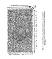
- FIG. 7 shows the atomic-scale imaging of a three nanometer M 2 C carbide in the optimally heat treated alloy 2C using three-dimensional Atom-Probe microanalysis [ M. K. Miller, Atom Probe Tomography, Kluwer Academic/Plenum Publishers, New York, NY, 2000 ] which is incorporated herewith, verifying that the designed size and particle composition have in fact been achieved.
- This image is an atomic reconstruction of a slab of the alloy where each atom is represented by a dot on the figure with a color and size corresponding to its element.
- the drawn circle in FIG. 7 represents the congregation of alloy carbide formers and carbon which define the M 2 C nanoscale carbide in the image.
- the alloys discovered have a range of combinations of elements as set forth in TABLE 36.
- TABLE 36 All values in % by weight C Co Ni Cr Si Mn Cu 0.1 to 0.3 8 to 17 0 to 10 6 to 11 ⁇ 1 ⁇ 0.5 ⁇ 0.15 With one or more of: Mo Nb V Ta W ⁇ 3 ⁇ 0.3 ⁇ 0.8 ⁇ 0.2 ⁇ 3 And one or more of: Ti La or other rare earths Zr B ⁇ 0.2 ⁇ 0.2 ⁇ 0.15 ⁇ 0.005 And the balance Fe
- the microstructure is primarily martensitic when processed as described and desirably is maintained as lath martensitic with less than 2.5% and preferably less than 1% by volume, retained or precipitated austenite.
- the microstructure is primarily inclusive of M 2 C nanoscale carbides where M is one or more element selected from the group including Mo, Nb, V, Ta, W and Cr. The formula, size and presence of the carbides are important.
- the carbides are present only in the form of M 2 C and to some extent, MC carbides,without the presence of other carbides and the size (average diameter) is less than about ten nanometers and preferably in the range of about three nanometers to five nanometers.
- the size (average diameter) is less than about ten nanometers and preferably in the range of about three nanometers to five nanometers.
- other larger scale incoherent carbides such as cementite, M 23 C 6 , M 6 C and M 7 C 3 .
- Other embrittling phases, such as topologically close packed (TCP) intermetallic phases, are also avoided.
- the martensitic matrix in which the strengthening nanocarbides are embedded contains an optimum balance of Co and Ni to maintain a sufficiently high M s temperature with sufficient Co to enhance Cr partitioning to the passivating oxide film, enhance M 2 C driving force and maintain dislocation nucleation of nanocarbides.
- Resistance to cleavage is enhanced by maintaining sufficient Ni and promoting grain refinement through stable MC carbide dispersions which resist coarsening at the normalizing or solution treatment temperature. Alloy composition and thermal processing are optimized to minimize or eliminate all other dispersed particles that limit toughness and fatigue resistance.
- Resistance to hydrogen stress corrosion is enhanced by grain boundary segregation of cohesion enhancing elements such as B, Mo and W, and through the hydrogen trapping effect of the nanoscale M 2 C carbide dispersion. Alloy composition is constrained to limit microsegregation under production-scale ingot solidification conditions.
- Subclass 1 is similar in composition to alloys 2C, 3A and 3B of TABLE 1 and is optimal for a secondary hardening temper at about 400°C to 600°C to precipitate Cr-Mo base M 2 C carbides providing a UTS in the range of about 270 ksi to 300 ksi.
- Subclass 2 is similar in composition to alloys 4D and 4E of TABLE 1 and includes additions of W and/or Si to destabilize cementite and provide greater thermal stability with a secondary hardening temper at about 400°C to 600°C to precipitate Cr-Mo-W base M 2 C carbides.
- subclass 3 is similar in composition to alloys 1, 2A and 2B in TABLE 1 and provides an intermediate UTS range of about 240 ksi to 270 ksi.
- Subclass 4 is similar in composition to alloys 4F and 4G of TABLE 1 and is optimal for low-temperature tempering at about 200°C to 300°C to precipitate Fe-base M 2 C carbides without the precipitation of cementite.
- Alloy subclass 5 is a most preferred embodiment of subclass 1.
- Subclass 6 is similar in composition to alloys 5B through 5F and 6A through 6K. Subclass 6 provides optimal toughness due to the higher Ni content but may require multiple tempering treatments with cryogenic treatments between steps in order to avoid significant amounts of retained austenite in the final microstructure.
- Subclass 7 is a further optimization of fracture toughness and is similar to alloys 6L and 6M where the lower Co content lowers the ductile to brittle transition temperature of the alloy.
- TABLE 37 All values in % by weight Alloy subclass C Co Ni Cr Mo W Si V Ti 1 0.20 to 0.26 11 to 15 2.0 to 3.0 7.5 to 9.5 1.0 to 2.0 ⁇ 0.1 ⁇ 0.25 0.1 to 0.5 0.01 to 0.05 2 0.20 to 0.25 12 to 15 2.0 to 3.0 7.0 to 9.0 1.0 to 3.0 ⁇ 2.5 ⁇ 0.75 0.1 to 0.5 0.01 to 0.05 3 0.10 to 0.20 12 to 17 2.5 to 5.0 8.5 to 9.5 1.0 to 2.0 ⁇ 0,1 ⁇ 0.25 0.1 to 0.5 0.01 to 0.05 4 0.25 to 0.28 11 to 15 1.0 to 3.0 7.0 to 9.0 ⁇ 1.0 ⁇ 0.1 ⁇ 1.0 0.1 to 0.5 0.01 to 0.05 5 0.22 to 0.25 12 to 13 2.5 to 3.0 8.5 to 9.5 1.0 to 1.5
- the invention including the class of ultrahigh-strength, corrosion resistant, structural steel alloys and the processes for making and using such alloys is to be limited only by the following claims and equivalents thereof.
Landscapes
- Chemical & Material Sciences (AREA)
- Engineering & Computer Science (AREA)
- Materials Engineering (AREA)
- Mechanical Engineering (AREA)
- Metallurgy (AREA)
- Organic Chemistry (AREA)
- Physics & Mathematics (AREA)
- Thermal Sciences (AREA)
- Crystallography & Structural Chemistry (AREA)
- Heat Treatment Of Steel (AREA)
- Physical Or Chemical Processes And Apparatus (AREA)
- Powder Metallurgy (AREA)
- Heat Treatment Of Articles (AREA)
- Compositions Of Oxide Ceramics (AREA)
Applications Claiming Priority (3)
| Application Number | Priority Date | Filing Date | Title |
|---|---|---|---|
| US10/071,688 US7235212B2 (en) | 2001-02-09 | 2002-02-08 | Nanocarbide precipitation strengthened ultrahigh strength, corrosion resistant, structural steels and method of making said steels |
| PCT/US2002/004111 WO2003018856A2 (fr) | 2001-02-09 | 2002-02-11 | Aciers speciaux anticorrosion a tres haute resistance, renforces par precipitation de nanocarbures |
| EP03736433A EP1481108B1 (fr) | 2002-02-08 | 2003-02-07 | Aciers structurels, resistants a la corrosion, a resistance tres elevee, renforces par une precipitation de nanocarbures |
Related Parent Applications (1)
| Application Number | Title | Priority Date | Filing Date |
|---|---|---|---|
| EP03736433.8 Division | 2003-02-07 |
Publications (2)
| Publication Number | Publication Date |
|---|---|
| EP2192206A1 true EP2192206A1 (fr) | 2010-06-02 |
| EP2192206B1 EP2192206B1 (fr) | 2013-06-12 |
Family
ID=27807121
Family Applications (2)
| Application Number | Title | Priority Date | Filing Date |
|---|---|---|---|
| EP10151840.5A Expired - Lifetime EP2192206B1 (fr) | 2002-02-08 | 2003-02-07 | Fabrication d'aciers structurels, résistant à la corrosion et à résistance ultra forte renforcée par des nanocarbure précipites |
| EP03736433A Expired - Lifetime EP1481108B1 (fr) | 2002-02-08 | 2003-02-07 | Aciers structurels, resistants a la corrosion, a resistance tres elevee, renforces par une precipitation de nanocarbures |
Family Applications After (1)
| Application Number | Title | Priority Date | Filing Date |
|---|---|---|---|
| EP03736433A Expired - Lifetime EP1481108B1 (fr) | 2002-02-08 | 2003-02-07 | Aciers structurels, resistants a la corrosion, a resistance tres elevee, renforces par une precipitation de nanocarbures |
Country Status (7)
| Country | Link |
|---|---|
| EP (2) | EP2192206B1 (fr) |
| AT (1) | ATE464403T1 (fr) |
| AU (1) | AU2003237775A1 (fr) |
| CA (1) | CA2475248C (fr) |
| DE (1) | DE60332100D1 (fr) |
| ES (1) | ES2342277T3 (fr) |
| WO (1) | WO2003076676A2 (fr) |
Cited By (2)
| Publication number | Priority date | Publication date | Assignee | Title |
|---|---|---|---|---|
| CN102319845A (zh) * | 2011-06-16 | 2012-01-18 | 南京迪威尔重型锻造股份有限公司 | 深海采油设备液压缸用钢锻件锻坯制造工艺 |
| CN114855098A (zh) * | 2022-04-22 | 2022-08-05 | 东北大学 | 一种工程机械用高强中锰钢及其制备方法 |
Families Citing this family (6)
| Publication number | Priority date | Publication date | Assignee | Title |
|---|---|---|---|---|
| US8801872B2 (en) * | 2007-08-22 | 2014-08-12 | QuesTek Innovations, LLC | Secondary-hardening gear steel |
| US8157931B2 (en) * | 2008-07-01 | 2012-04-17 | Northwestern University | Case hardenable nickel-cobalt steel |
| CN114921629B (zh) * | 2022-07-20 | 2022-11-15 | 中北大学 | 一种7Cr14马氏体不锈钢及其碳化物的细化工艺 |
| CN116577170B (zh) * | 2023-05-18 | 2024-03-01 | 陕西长羽航空装备股份有限公司 | 航空发动机零部件测试用MoNiCr合金金相组织腐蚀方法及应用 |
| CN117947359A (zh) * | 2024-01-22 | 2024-04-30 | 东北大学 | 一种高强度Fe-Mn基半硬磁磁滞合金及其制备方法 |
| CN117925970B (zh) * | 2024-03-22 | 2024-07-02 | 成都先进金属材料产业技术研究院股份有限公司 | 一种热锻模具钢的制备方法 |
Citations (5)
| Publication number | Priority date | Publication date | Assignee | Title |
|---|---|---|---|---|
| US5221372A (en) * | 1992-02-13 | 1993-06-22 | Northwestern University | Fracture-tough, high hardness stainless steel and method of making same |
| US5310431A (en) * | 1992-10-07 | 1994-05-10 | Robert F. Buck | Creep resistant, precipitation-dispersion-strengthened, martensitic stainless steel and method thereof |
| US5358577A (en) * | 1990-05-28 | 1994-10-25 | Hitachi Metals, Ltd. | High strength and high toughness martensitic stainless steel and method of manufacturing the same |
| EP0739994A1 (fr) * | 1995-04-27 | 1996-10-30 | Hitachi Metals, Ltd. | Acier pour paliers, pièces pour paliers ayant une résistance thermique et une ductilité améliorée et un procédé de fabrication de ces pièces |
| US6176946B1 (en) * | 1998-01-28 | 2001-01-23 | Northwestern University | Advanced case carburizing secondary hardening steels |
-
2003
- 2003-02-07 EP EP10151840.5A patent/EP2192206B1/fr not_active Expired - Lifetime
- 2003-02-07 ES ES03736433T patent/ES2342277T3/es not_active Expired - Lifetime
- 2003-02-07 EP EP03736433A patent/EP1481108B1/fr not_active Expired - Lifetime
- 2003-02-07 AU AU2003237775A patent/AU2003237775A1/en not_active Abandoned
- 2003-02-07 AT AT03736433T patent/ATE464403T1/de active
- 2003-02-07 DE DE60332100T patent/DE60332100D1/de not_active Expired - Lifetime
- 2003-02-07 CA CA2475248A patent/CA2475248C/fr not_active Expired - Lifetime
- 2003-02-07 WO PCT/US2003/003682 patent/WO2003076676A2/fr not_active Ceased
Patent Citations (5)
| Publication number | Priority date | Publication date | Assignee | Title |
|---|---|---|---|---|
| US5358577A (en) * | 1990-05-28 | 1994-10-25 | Hitachi Metals, Ltd. | High strength and high toughness martensitic stainless steel and method of manufacturing the same |
| US5221372A (en) * | 1992-02-13 | 1993-06-22 | Northwestern University | Fracture-tough, high hardness stainless steel and method of making same |
| US5310431A (en) * | 1992-10-07 | 1994-05-10 | Robert F. Buck | Creep resistant, precipitation-dispersion-strengthened, martensitic stainless steel and method thereof |
| EP0739994A1 (fr) * | 1995-04-27 | 1996-10-30 | Hitachi Metals, Ltd. | Acier pour paliers, pièces pour paliers ayant une résistance thermique et une ductilité améliorée et un procédé de fabrication de ces pièces |
| US6176946B1 (en) * | 1998-01-28 | 2001-01-23 | Northwestern University | Advanced case carburizing secondary hardening steels |
Non-Patent Citations (2)
| Title |
|---|
| CAMPBELL C.E., OLSON G.B.: "Systems design of high performance stainless steels. I. Conceptual and computational design", JOURNAL OF COMPUTER-AIDED MATERIALS DESIGN, vol. 7, no. 3, 2000, KLUWER ACADEMIC/ESCOM NETHERLANDS, pages 145 - 170, XP009037218, ISSN: 0928-1045 * |
| CAMPBELL C.E., OLSON G.B.: "Systems design of high performance stainless steels. II. Prototype characterization", JOURNAL OF COMPUTER-AIDED MATERIALS DESIGN, vol. 7, no. 3, 2000, KLUWER ACADEMIC/ESCOM NETHERLANDS, pages 171 - 194, XP009037219, ISSN: 0928-1045 * |
Cited By (3)
| Publication number | Priority date | Publication date | Assignee | Title |
|---|---|---|---|---|
| CN102319845A (zh) * | 2011-06-16 | 2012-01-18 | 南京迪威尔重型锻造股份有限公司 | 深海采油设备液压缸用钢锻件锻坯制造工艺 |
| CN102319845B (zh) * | 2011-06-16 | 2012-10-10 | 南京迪威尔高端制造股份有限公司 | 深海采油设备液压缸用钢锻件锻坯制造工艺 |
| CN114855098A (zh) * | 2022-04-22 | 2022-08-05 | 东北大学 | 一种工程机械用高强中锰钢及其制备方法 |
Also Published As
| Publication number | Publication date |
|---|---|
| ATE464403T1 (de) | 2010-04-15 |
| CA2475248C (fr) | 2011-04-05 |
| CA2475248A1 (fr) | 2003-09-18 |
| EP1481108A1 (fr) | 2004-12-01 |
| WO2003076676A8 (fr) | 2004-10-28 |
| ES2342277T3 (es) | 2010-07-05 |
| DE60332100D1 (de) | 2010-05-27 |
| EP1481108B1 (fr) | 2010-04-14 |
| AU2003237775A1 (en) | 2003-09-22 |
| WO2003076676A2 (fr) | 2003-09-18 |
| AU2003237775A8 (en) | 2003-09-22 |
| EP2192206B1 (fr) | 2013-06-12 |
Similar Documents
| Publication | Publication Date | Title |
|---|---|---|
| EP1368504B1 (fr) | Aciers speciaux anticorrosion a tres haute resistance, renforces par precipitation de nanocarbures | |
| EP0664342B1 (fr) | Alliage d'acier inoxydable de cémentation par le carbone pour utilisations à haute température | |
| US6531007B1 (en) | Method for the manufacture of steel products of a precipitation hardened martensitic steel, steel products obtained with such method and use of said steel products | |
| Rohrbach et al. | Maraging steels | |
| CA2528165A1 (fr) | Aciers de construction anticorrosion a ultra-haute resistance renforce par nano-precipitation | |
| JP7580480B2 (ja) | 高破壊靭性かつ高強度の析出硬化型ステンレス鋼 | |
| JPH10235447A5 (fr) | ||
| Ludwigson et al. | The physical metallurgy of precipitation-hardenable stainless steels | |
| EP1481108B1 (fr) | Aciers structurels, resistants a la corrosion, a resistance tres elevee, renforces par une precipitation de nanocarbures | |
| US20050103408A1 (en) | Nanocarbide precipitation strengthened ultrahigh-strength, corrosion resistant, structural steels | |
| JPH09249940A (ja) | 耐硫化物応力割れ性に優れる高強度鋼材およびその製造方法 | |
| JPH0260748B2 (fr) | ||
| JP4732694B2 (ja) | ナノカーバイド析出強化超高強度耐食性構造用鋼 | |
| San-Martin et al. | Stainless steels | |
| CN1849404A (zh) | 纳米沉积增强的超高强度的、抗腐蚀的结构钢 | |
| Lozano et al. | Metallurgical Fundamentals of Quenching | |
| Gavriljuk | High Strength Stainless Austenitic CrMnCN Steels-Part I: Alloy Design and Properties | |
| JPH01205029A (ja) | 高温用高Crフェライト鋼材の製造方法 | |
| KR20220149776A (ko) | 강 물품 및 그 제조 방법 | |
| JPH02190442A (ja) | 温間鍛造用肌焼鋼 |
Legal Events
| Date | Code | Title | Description |
|---|---|---|---|
| PUAI | Public reference made under article 153(3) epc to a published international application that has entered the european phase |
Free format text: ORIGINAL CODE: 0009012 |
|
| AC | Divisional application: reference to earlier application |
Ref document number: 1481108 Country of ref document: EP Kind code of ref document: P |
|
| AK | Designated contracting states |
Kind code of ref document: A1 Designated state(s): AT BE BG CH CY CZ DE DK EE ES FI FR GB GR HU IE IT LI LU MC NL PT SE SI SK TR |
|
| 17P | Request for examination filed |
Effective date: 20101201 |
|
| 17Q | First examination report despatched |
Effective date: 20110425 |
|
| R17C | First examination report despatched (corrected) |
Effective date: 20110503 |
|
| GRAP | Despatch of communication of intention to grant a patent |
Free format text: ORIGINAL CODE: EPIDOSNIGR1 |
|
| GRAS | Grant fee paid |
Free format text: ORIGINAL CODE: EPIDOSNIGR3 |
|
| GRAA | (expected) grant |
Free format text: ORIGINAL CODE: 0009210 |
|
| AC | Divisional application: reference to earlier application |
Ref document number: 1481108 Country of ref document: EP Kind code of ref document: P |
|
| AK | Designated contracting states |
Kind code of ref document: B1 Designated state(s): AT BE BG CH CY CZ DE DK EE ES FI FR GB GR HU IE IT LI LU MC NL PT SE SI SK TR |
|
| REG | Reference to a national code |
Ref country code: GB Ref legal event code: FG4D |
|
| REG | Reference to a national code |
Ref country code: CH Ref legal event code: EP |
|
| REG | Reference to a national code |
Ref country code: AT Ref legal event code: REF Ref document number: 616726 Country of ref document: AT Kind code of ref document: T Effective date: 20130615 |
|
| REG | Reference to a national code |
Ref country code: IE Ref legal event code: FG4D |
|
| REG | Reference to a national code |
Ref country code: DE Ref legal event code: R096 Ref document number: 60344295 Country of ref document: DE Effective date: 20130808 |
|
| PG25 | Lapsed in a contracting state [announced via postgrant information from national office to epo] |
Ref country code: GR Free format text: LAPSE BECAUSE OF FAILURE TO SUBMIT A TRANSLATION OF THE DESCRIPTION OR TO PAY THE FEE WITHIN THE PRESCRIBED TIME-LIMIT Effective date: 20130913 Ref country code: SI Free format text: LAPSE BECAUSE OF FAILURE TO SUBMIT A TRANSLATION OF THE DESCRIPTION OR TO PAY THE FEE WITHIN THE PRESCRIBED TIME-LIMIT Effective date: 20130612 Ref country code: ES Free format text: LAPSE BECAUSE OF FAILURE TO SUBMIT A TRANSLATION OF THE DESCRIPTION OR TO PAY THE FEE WITHIN THE PRESCRIBED TIME-LIMIT Effective date: 20130923 Ref country code: SE Free format text: LAPSE BECAUSE OF FAILURE TO SUBMIT A TRANSLATION OF THE DESCRIPTION OR TO PAY THE FEE WITHIN THE PRESCRIBED TIME-LIMIT Effective date: 20130612 Ref country code: FI Free format text: LAPSE BECAUSE OF FAILURE TO SUBMIT A TRANSLATION OF THE DESCRIPTION OR TO PAY THE FEE WITHIN THE PRESCRIBED TIME-LIMIT Effective date: 20130612 |
|
| REG | Reference to a national code |
Ref country code: NL Ref legal event code: VDEP Effective date: 20130612 |
|
| PG25 | Lapsed in a contracting state [announced via postgrant information from national office to epo] |
Ref country code: BG Free format text: LAPSE BECAUSE OF FAILURE TO SUBMIT A TRANSLATION OF THE DESCRIPTION OR TO PAY THE FEE WITHIN THE PRESCRIBED TIME-LIMIT Effective date: 20130912 |
|
| PG25 | Lapsed in a contracting state [announced via postgrant information from national office to epo] |
Ref country code: EE Free format text: LAPSE BECAUSE OF FAILURE TO SUBMIT A TRANSLATION OF THE DESCRIPTION OR TO PAY THE FEE WITHIN THE PRESCRIBED TIME-LIMIT Effective date: 20130612 Ref country code: PT Free format text: LAPSE BECAUSE OF FAILURE TO SUBMIT A TRANSLATION OF THE DESCRIPTION OR TO PAY THE FEE WITHIN THE PRESCRIBED TIME-LIMIT Effective date: 20131014 Ref country code: SK Free format text: LAPSE BECAUSE OF FAILURE TO SUBMIT A TRANSLATION OF THE DESCRIPTION OR TO PAY THE FEE WITHIN THE PRESCRIBED TIME-LIMIT Effective date: 20130612 Ref country code: CZ Free format text: LAPSE BECAUSE OF FAILURE TO SUBMIT A TRANSLATION OF THE DESCRIPTION OR TO PAY THE FEE WITHIN THE PRESCRIBED TIME-LIMIT Effective date: 20130612 Ref country code: BE Free format text: LAPSE BECAUSE OF FAILURE TO SUBMIT A TRANSLATION OF THE DESCRIPTION OR TO PAY THE FEE WITHIN THE PRESCRIBED TIME-LIMIT Effective date: 20130612 |
|
| PG25 | Lapsed in a contracting state [announced via postgrant information from national office to epo] |
Ref country code: NL Free format text: LAPSE BECAUSE OF FAILURE TO SUBMIT A TRANSLATION OF THE DESCRIPTION OR TO PAY THE FEE WITHIN THE PRESCRIBED TIME-LIMIT Effective date: 20130612 |
|
| PLBE | No opposition filed within time limit |
Free format text: ORIGINAL CODE: 0009261 |
|
| STAA | Information on the status of an ep patent application or granted ep patent |
Free format text: STATUS: NO OPPOSITION FILED WITHIN TIME LIMIT |
|
| PG25 | Lapsed in a contracting state [announced via postgrant information from national office to epo] |
Ref country code: DK Free format text: LAPSE BECAUSE OF FAILURE TO SUBMIT A TRANSLATION OF THE DESCRIPTION OR TO PAY THE FEE WITHIN THE PRESCRIBED TIME-LIMIT Effective date: 20130612 |
|
| 26N | No opposition filed |
Effective date: 20140313 |
|
| REG | Reference to a national code |
Ref country code: DE Ref legal event code: R097 Ref document number: 60344295 Country of ref document: DE Effective date: 20140313 |
|
| REG | Reference to a national code |
Ref country code: DE Ref legal event code: R119 Ref document number: 60344295 Country of ref document: DE |
|
| PG25 | Lapsed in a contracting state [announced via postgrant information from national office to epo] |
Ref country code: MC Free format text: LAPSE BECAUSE OF FAILURE TO SUBMIT A TRANSLATION OF THE DESCRIPTION OR TO PAY THE FEE WITHIN THE PRESCRIBED TIME-LIMIT Effective date: 20130612 Ref country code: LU Free format text: LAPSE BECAUSE OF FAILURE TO SUBMIT A TRANSLATION OF THE DESCRIPTION OR TO PAY THE FEE WITHIN THE PRESCRIBED TIME-LIMIT Effective date: 20140207 |
|
| REG | Reference to a national code |
Ref country code: CH Ref legal event code: PL |
|
| GBPC | Gb: european patent ceased through non-payment of renewal fee |
Effective date: 20140207 |
|
| PG25 | Lapsed in a contracting state [announced via postgrant information from national office to epo] |
Ref country code: LI Free format text: LAPSE BECAUSE OF NON-PAYMENT OF DUE FEES Effective date: 20140228 Ref country code: CH Free format text: LAPSE BECAUSE OF NON-PAYMENT OF DUE FEES Effective date: 20140228 |
|
| REG | Reference to a national code |
Ref country code: FR Ref legal event code: ST Effective date: 20141031 |
|
| REG | Reference to a national code |
Ref country code: IE Ref legal event code: MM4A |
|
| REG | Reference to a national code |
Ref country code: DE Ref legal event code: R119 Ref document number: 60344295 Country of ref document: DE Effective date: 20140902 |
|
| PG25 | Lapsed in a contracting state [announced via postgrant information from national office to epo] |
Ref country code: IE Free format text: LAPSE BECAUSE OF NON-PAYMENT OF DUE FEES Effective date: 20140207 Ref country code: GB Free format text: LAPSE BECAUSE OF NON-PAYMENT OF DUE FEES Effective date: 20140207 Ref country code: DE Free format text: LAPSE BECAUSE OF NON-PAYMENT OF DUE FEES Effective date: 20140902 Ref country code: FR Free format text: LAPSE BECAUSE OF NON-PAYMENT OF DUE FEES Effective date: 20140228 |
|
| REG | Reference to a national code |
Ref country code: AT Ref legal event code: MM01 Ref document number: 616726 Country of ref document: AT Kind code of ref document: T Effective date: 20140207 |
|
| PG25 | Lapsed in a contracting state [announced via postgrant information from national office to epo] |
Ref country code: AT Free format text: LAPSE BECAUSE OF NON-PAYMENT OF DUE FEES Effective date: 20140207 |
|
| PG25 | Lapsed in a contracting state [announced via postgrant information from national office to epo] |
Ref country code: CY Free format text: LAPSE BECAUSE OF FAILURE TO SUBMIT A TRANSLATION OF THE DESCRIPTION OR TO PAY THE FEE WITHIN THE PRESCRIBED TIME-LIMIT Effective date: 20130612 Ref country code: IT Free format text: LAPSE BECAUSE OF NON-PAYMENT OF DUE FEES Effective date: 20140207 |
|
| PG25 | Lapsed in a contracting state [announced via postgrant information from national office to epo] |
Ref country code: TR Free format text: LAPSE BECAUSE OF FAILURE TO SUBMIT A TRANSLATION OF THE DESCRIPTION OR TO PAY THE FEE WITHIN THE PRESCRIBED TIME-LIMIT Effective date: 20130612 Ref country code: HU Free format text: LAPSE BECAUSE OF FAILURE TO SUBMIT A TRANSLATION OF THE DESCRIPTION OR TO PAY THE FEE WITHIN THE PRESCRIBED TIME-LIMIT; INVALID AB INITIO Effective date: 20030207 |