EP2192209A2 - Dispositif à nettoyage des composants oxydés ou corrodés en présence d'un mélange gazeux de halogènes - Google Patents
Dispositif à nettoyage des composants oxydés ou corrodés en présence d'un mélange gazeux de halogènes Download PDFInfo
- Publication number
- EP2192209A2 EP2192209A2 EP09175543A EP09175543A EP2192209A2 EP 2192209 A2 EP2192209 A2 EP 2192209A2 EP 09175543 A EP09175543 A EP 09175543A EP 09175543 A EP09175543 A EP 09175543A EP 2192209 A2 EP2192209 A2 EP 2192209A2
- Authority
- EP
- European Patent Office
- Prior art keywords
- central tube
- gas
- halogen
- containing gas
- reactor
- Prior art date
- Legal status (The legal status is an assumption and is not a legal conclusion. Google has not performed a legal analysis and makes no representation as to the accuracy of the status listed.)
- Granted
Links
Images


Classifications
-
- C—CHEMISTRY; METALLURGY
- C23—COATING METALLIC MATERIAL; COATING MATERIAL WITH METALLIC MATERIAL; CHEMICAL SURFACE TREATMENT; DIFFUSION TREATMENT OF METALLIC MATERIAL; COATING BY VACUUM EVAPORATION, BY SPUTTERING, BY ION IMPLANTATION OR BY CHEMICAL VAPOUR DEPOSITION, IN GENERAL; INHIBITING CORROSION OF METALLIC MATERIAL OR INCRUSTATION IN GENERAL
- C23G—CLEANING OR DE-GREASING OF METALLIC MATERIAL BY CHEMICAL METHODS OTHER THAN ELECTROLYSIS
- C23G5/00—Cleaning or de-greasing metallic material by other methods; Apparatus for cleaning or de-greasing metallic material with organic solvents
-
- F—MECHANICAL ENGINEERING; LIGHTING; HEATING; WEAPONS; BLASTING
- F01—MACHINES OR ENGINES IN GENERAL; ENGINE PLANTS IN GENERAL; STEAM ENGINES
- F01D—NON-POSITIVE DISPLACEMENT MACHINES OR ENGINES, e.g. STEAM TURBINES
- F01D25/00—Component parts, details, or accessories, not provided for in, or of interest apart from, other groups
- F01D25/002—Cleaning of turbomachines
Definitions
- the invention relates to a device for cleaning oxidized or corroded components in the presence of a halogen-containing gas mixture, with a purification reactor, in the middle or immediately opens a feed line which is connected via a flow control device with a gas-storing the halogen-containing gas mixture gas reservoir.
- these components can be turbine components acted upon by hot gases, in particular gas turbine blades.
- Turbine components for engines or stationary gas turbine plants which are exposed to medium or direct hot gas flows, such as guide or moving blades, heat accumulation segments or similar components or groups of components delimiting the hot gas channel are subject to operational material degradation, which often leads to cracks and, associated therewith, mechanical weakening of the respective components , Due to the prevailing in the hot gas channels high temperature and pressure loads, which are exposed to the corresponding mostly made of nickel-based components, divide with increasing operating time by external and internal oxidation complex chemically and thermally stable oxides on the component surfaces, within the forming crack openings and in near-surface areas within the base material.
- the aim is to transfer the claimed and partially damaged components with a special process chain in a state that largely corresponds to the state of a newly manufactured, comparable component.
- one of the steps is to thoroughly clean the component to be reworked, i. to eliminate the deposited on the component surface and in the cracks formed complex oxide layer, without damaging the material of the component itself.
- reaction chamber in which a halogen-containing gas mixture is introduced for the purpose of component cleaning, be temporarily rinsed with a non-halogen-containing gas during the cleaning.
- the US 6,536,135 B2 describes an FIC process in which an improved O-xidalism by varying the partial pressures of the cleaning gas mixture is made by the consisting of hydrogen fluoride (HF) and hydrogen (H 2 ) cleaning gas mixture is added as another component carbon.
- the carbon is added in the form of various compounds which form a carbonaceous gas during the process.
- a typical purification reactor which provides a cylindrical housing which is gas-tight from above and can be fitted in an open state from above with components to be cleaned.
- the components to be cleaned are housed on vertically stacked storage levels, so-called trays, which are attached to a centrally located in the cleaning reactor central tube through which a carbon-enriched hydrogen fluoride gas mixture is fed to the purification reactor.
- the reactor head penetrating the gas-tight central tube extends vertically within the cleaning reactor down into the region of the so-called reactor sump, in which the central tube is a substantially over the entire Cross-section of the cleaning reactor extending gas distributor structure provides with outlet openings through which the halogen-containing cleaning gas mixture is fed from bottom to top in the purification reactor.
- the cleaning gas mixture flows through the entire reactor volume from the reactor sump in the direction of the reactor head, at which a corresponding Gausauslassö réelle is provided.
- the Applicant also has many years of practical experience in the field of cleaning operationally contaminated, corroded, oxidized and degraded gas turbine components of the type discussed above, in particular using FIC purification techniques and the cleaning equipment required therefor.
- a relevant purification reactor which is fed via a central tube with a cleaning gas mixture containing hydrogen fluoride and hydrogen in varying ratios, it has been shown that significant disturbances in the cleaning process caused by volume fluctuations in the supply of the cleaning gas in the purification reactor, which may occasionally lead to the termination of the entire cleaning process if certain levels are exceeded.
- the invention is based on the object, a device for the purification of oxidized or corroded components, in particular of hot gases exposed gas turbine components, in the presence of a halogen-containing gas, with a usually kesselelförmig formed purification reactor, in the middle or directly opens a feed line, which via a flow control device with a reservoir storing the halogen-containing gas, in such a way that, on the one hand, care is taken to completely eliminate the problems associated with an insufficient or fluctuating cleaning gas feed into the purification reactor.
- the solution according to the device according to the features of the preamble of claim 1 is characterized in that the flow control device in sequence along the flow direction of the feed line flowing through the halogen-containing gas provides a gas flow control valve, a heat exchanger unit and a gas flow measuring unit.
- the device according to the invention is based on the finding that form condensations along the feed line for the supply of the halogen-containing gas, which occur in particular in the region of throttle points. Such condensations lead to erroneous values in the range of the gas flow control and can lead to total failure of the quantity measurement.
- the halogen-containing gas is preferably stored in pressure bottles. Under the storage conditions, it is liquid. By raising the temperature, the liquid becomes evaporates, and it adjusts the temperature-dependent vapor pressure of the substance. Before the gas control thus prevail overpressure conditions.
- the pressure within the purification reactor is typically at the pressure level of 50 Torr to 780 Torr. Therefore, it requires along the feed line at least one pressure-reducing throttle stage. In this case, the above condensation problem occurs.
- the device according to the invention contains as throttle point along the feed line at least one flow control device which provides a gas-expanding gas flow control valve.
- a heating unit is provided immediately downstream of the gas flow control valve, which preferably has a gas heater, whereby the temperature level in this line region is raised above the condensation level of the halogen-containing gas, preferably HF gas.
- the gas flow measuring unit Downstream along the feed line to the heat exchanger is immediately followed by the gas flow measuring unit.
- a heating of the heat exchanger using a variety of heating techniques is possible.
- the use of electrical heating has proved to be particularly advantageous.
- appropriately heated heat transfer medium or other heating media the line area downstream of the gas flow control valve.
- the heat exchanger unit is to be designed or selected with respect to its heat output such that a temperature level between 22 ° C and 75 ° C, preferably 40 ° C to 50 ° C and particularly preferably 44 ° C to 46 ° C can be adjusted.
- a shut-off valve is provided upstream and downstream of the flow control device in the feed line, which in each case can be actuated automatically or manually in the event of a possible failure of the flow control device.
- a bypass line to the flow control device along the feed line is provided, along which a control valve, preferably a manual control valve, is introduced.
- a device with the features according to the preamble of claim 9, which is directly or indirectly connected to the at least one feed line, is characterized Provides central tube, which extends from the reactor head to the reactor sump within the purification reactor and is connected in the region of the reactor sump with a radially extending to the central tube, the first manifold structure having outlet openings for the halogen-containing gas, solution according to the fact that the first manifold structure a support plane for the components to be cleaned, and a second distributor structure is provided which is spaced from the first distributor structure attached to the central tube.
- the first distributor structure forms a supporting plane extending radially to the central tube for the components to be cleaned, wherein the distributor structures have outlet openings for the halogen-containing gas, at least in the direction of the components resting thereon.
- the novel gas distribution concept provides for the arrangement of preferably a plurality of so-called distributor structures arranged one above the other along the central tube before, which are either self-supporting attached to the central tube or combined with suitably formed support structures along the central tube.
- the novel decentralized gas distribution in the purifying reactor serves to distribute the process gas as optimally as possible by adding and removing the purge gas to each individual component under largely identical conditions. Due to an individual cleaning gas feed in each individual support level for the components to be cleaned, it is ensured that each individual component is directly and suitably supplied with cleaning gas.
- the number and arrangement of the provided in the respective distribution structure outlet openings can be chosen basically arbitrary, but preferably taking into account the shape, size and arrangement of the components to be cleaned.
- the distributor structures which are each mounted along the central tube at an axial distance and which, depending on the design, can be integrated into stable support structures or formed in the form of intrinsically stable plate or tube constructions, are made of a material which is resistant to the process conditions prevailing in the purification reactor for this IN600 (Inconel 600).
- the cleaning reactor is to be equipped with a suitable number of distribution structures to be arranged along the central tube, onto which the components to be cleaned are to be applied.
- the individual distributor structures can be introduced in a modular manner and taking into account the cleaning task described above.
- the distributor structures have a central sleeve with a sleeve opening for receiving the central tube.
- the individual distributor structures can be positioned and fixed along the central tube.
- a corresponding number of cylindrical spacer sleeves are provided, which are slid longitudinally over the central tube as spacers and fix the sleeves provided with the distributor structures spaced apart from each other along the central tube.
- the distributor structures extending radially from the sleeve can be formed or implemented in different ways. Plate-shaped or grid-shaped or tubular formations for the distributor structure have proven to be particularly advantageous.
- at least one of the central tube radially extending stub is provided, spaced from the radial to the central tube at least one central tube annularly circulating ring line is mounted.
- the respective outlet openings are borne along the at least one stub line and the at least one ring line borne in each case oriented upwards, so that the resting on the distributor structure components are acted upon directly by the emerging from the outlet openings cleaning gas.
- the cuffs described above, with which the distributor structure is connected have gas openings oriented radially relative to the central tube, through which the cleaning gas radially emerging from the central tube via corresponding gas outlet openings can reach the respective distributor structures. Details of this can be found in the further description with reference to the figures.
- the respective distributor structures are disc-shaped and each have an upper and a lower disc plate on, which include a gap, which is also surrounded gas-tight by a disk rim which connects the two disc plates at its peripheral edge in a fluid-tight manner.
- the disk volume limited in this way is fed via an opening facing the central pipe with the halogen-containing cleaning gas, which can escape from the disk volume at least via outlet openings introduced in the upper disk plate.
- the number, arrangement or orientation and the diameter of the individual outlet openings are basically variably adjustable over a wide range. Thus, for example, between 100 and 10000 holes or outlet openings are provided per diameter structure, each with diameters between 0.1 mm to 5 mm.
- outlet openings Depending on the dimensions of the purification reactor and the components to be cleaned within the purification reactor, in practice preferred dimensions for the outlet openings have been provided, which provide 1000 to 5000 outlet openings per distribution structure, each with diameters between 0.5 and 2.5 mm.
- outlet openings For the purpose of an improved, matched to the shape and size of each component to be cleaned flow of cleaning gas, it is appropriate to arrange the outlet openings with respect to the generally circular support level sectorally suitable or distribute, for example in the form of radial lines or radially and in the circumferential direction ordered field pattern in which the outlet openings are arranged in groups summarized.
- the outlet openings in the form of conventional bores, it is particularly advantageous to tailor the outlet openings so that the individual gas streams emerging from the outlet openings strike the respective component to be cleaned at an optimized flow rate and with a predeterminable outflow direction.
- the gas outlet direction influencing flow outlet elements which can be formed in a suitable manner already during the production of the outlet openings, for example in the context of shaping punching processes.
- the distributor structures not only provide outlet openings for the cleaning gas at the upper side facing the support plane in order to apply cleaning gas to the components resting on the respective distributor structures, but moreover corresponding outlet openings are provided on the opposite lower side in order to provide a cleaning gas Align part of the cleaning gas exiting through the distributor structure with those components that rest on the support level directly below.
- Such optional additional components can preferably be installed between the respective distributor structures or directly on the components to be cleaned, in order to apply certain areas of components to the cleaning gas in a particular manner or to shield certain areas from the cleaning gas in order to make direct contact with them to avoid the cleaning gas.
- FIG. 1 illustrates a schematic structure of a purification reactor (right half of the figure), which is supplied via a cleaning gas line system (left half of the figure) with a cleaning gas mixture.
- the cleaning reactor has a substantially cylinder-shaped or barrel-shaped reactor housing 11, which is closed gas-tight on its upper side with a reactor cover 14.
- the reactor housing 11 is surrounded by a heating jacket 12 in which heaters 13 provide a cleaning process temperature inside the purification reactor of up to 1200 ° C.
- a central tube 23 is centrally provided which penetrates the reactor cover 14 gas-tight to the outside, and into which via a feed line 10 cleaning gas is fed.
- a reactor outlet 24 is provided within the purification reactor, is brought via the spent cleaning gas via a corresponding exhaust pipe 25 to the outside for further supply and disposal.
- two gas reservoirs 1, 1 ' namely a gas reservoir for the provision of hydrogen fluoride (HF) and a gas reservoir for the provision of hydrogen gas (H 2 ). Both types of gas are to be mixed in a suitable manner before being fed into the feed line 10 with a predetermined mixing ratio.
- a flow control device connects, which consists of a gas flow control valve 5, a heat exchanger unit 9, preferably in the form of a gas heater and a gas flow measuring unit 6 is.
- the immediately downstream of the gas flow control valve 5 subsequent heat exchanger unit 9 ensures a significant increase in temperature on the condensation temperature of the HF gas, so that a non-affected by any condensation processes HF gas supply can be ensured using the flow control device.
- a gas temperature control circuit 8 For monitoring and control of the heat exchanger unit 9 is a gas temperature control circuit 8.
- a suitable gas flow control loop 7 is provided for the controlled implementation of the gas flow measurement.
- a bypass line 2 is additionally provided, in which a shut-off valve, preferably a manual control valve 4, is mounted.
- the bypass line 2 is used in the case in which the flow control device, consisting of the gas flow control valve 5 of the heat exchanger unit 9 and the gas flow measuring unit 6 upstream and downstream with the help of two block valves 3 is separated from the gas supply.
- the used block valves 3 may preferably be in the form of valves, taps or slides, which can be driven both manually and automatically.
- the provided in the bypass line 2 manual control valve is preferably designed as a needle passage valve, which allows a very finely metered adjustment of the HF gas flow.
- the HF cleaning gas mixture fed into the central tube 23 along the feed line 10 exits within the process chamber 16 of the purification reactor via distributor structures 20 mounted at different levels along the central tube 23 and on which the components 26 to be cleaned each rest.
- the distributor structures 20 provided in the process space 16 are designed separately for support structures 19 likewise mounted radially on the central tube 23 and on which the distributor structures 20 are supported.
- the cleaning gas passes through the central tube 23 in each case in the distributor structures 20, of which it is directed directly to the components 26 to be cleaned exit.
- Additional provided within the process chamber 16 Gasleitbleche 27, 28 and 29 provide for an individual flow of the individual components to be cleaned 26 with cleaning gas.
- the lowest distribution structure 20 which is integrated in a stable bottom support 21, which is preferably fixedly connected to the central tube 23.
- a heat shield 22 is attached to the central tube 23 in the upper region within the purification reactor.
- FIG. 2 is a perspective view of a preferred embodiment of a distribution structure 20 is shown.
- the distributor structure 20 has a central sleeve 43, which can be pushed forcibly guided over the central tube, not shown. Only the completeness it should be noted that instead of the sleeve, the manifold structure 20 may also be connected directly to the central tube 23, in this case, the component 43 corresponds to the central tube.
- stub lines 40 Radially starting from the sleeve 43, four stub lines 40 adjoin these, to which concentric ring lines 41 are respectively connected.
- the stub lines 40 and ring lines 41 form a communicating piping system, which is supplied from the central tube 23, not shown, with cleaning gas.
- the sleeve 43 openings (not shown) via which the cleaning gas provided by the central tube 23 can be fed into the distribution system.
- the distribution structure 20 is eigentragschreib and robust and firmly enough connected to the sleeve 43 to accommodate both the weight of the manifold structure 20 and the weight of applied to the manifold structure 20 to be cleaned components 26.
- the outlet openings provided along the stub lines 40 and ring lines 41, via which the cleaning gas exits in the direction of the components resting on the distributor structure 20, are shown.
- FIG. 3 strongly schematically illustrates an alternative embodiment of a distributor structure, which is plate-shaped.
- the manifold structure in this case has an upper 50 and lower 51 disc plate, both plates 50 and 51 are bounded by a circumferential disc rim 52 and include an internal volume.
- the distributor structure is connected to a mechanically stable support structure 54.
- the upper disk plate 50 has sectors, characterized by boundary lines 55, which extend in the illustrated case along each radially. The individual sectors can be exchanged in order to adapt the reactor as variably as possible to different component types.
- the plate-shaped distributor structure is penetrated by the central tube 23, to which the distributor structure 20 is firmly attached.
- the manifold structure is connected to a cuff described above, which is threaded over the central tube 23.
- FIG. 4 is a perspective cross-sectional view represented by a plate-shaped distribution structure.
- the upper and lower disc plates 50, 51 are directly attached to the central central tube 23.
- 23 may be a cuff.
- cleaning gas supplied through the central tube or sleeve 23 passes into the intermediate space between the upper and lower disc plates 50, 51.
- suitable outlet openings 56 which are incorporated in the upper disc plate 50, the cleaning gas finally exits into the process space.
- the outlet openings 56 are preferably arranged in consideration of the components to be cleaned, which are to be applied to the upper disc plate 50, respectively. This in FIG. 4 illustrated embodiment provides sectoral field-like pattern order for the outlet openings 56.
- FIG. 4 illustrated embodiment provides sectoral field-like pattern order for the outlet openings 56.
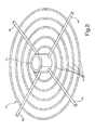
- FIG. 5 the plan view of a segment surface of the upper disc plate 50 is shown, in which a plurality of fields 57 are arranged, each composed of a plurality of individual outlet openings 56.
- the arrangement as well as the number of outlet openings 56 within the individual fields 57 can each be identical or different, preferably be selected depending on the respective components to be cleaned.
- FIG. 6 schematically shows an enlarged view of a field 57, in which a plurality of individual outlet openings 56 is provided. Based on the sectional views AA and BB, the contours of the individual outlet openings are visible. In particular, it can be seen from the sectional representation AA that each individual outlet opening 56 is covered by a flow guide element 58, whereby the outlet flow can be spatially directed onto the respective component.
- the optimized control and gas distribution helps to significantly reduce the amount of HF gas to be injected for cleaning purposes. On the one hand, this reduces the risk of damage to the individual components while simultaneously improving the cleaning effect. On the other hand, this can be safely avoided over-etched surface areas on the components. In addition, the entire system is less burdened by the chemically highly reactive cleaning gas, so that the life and use of such systems and their components can be significantly extended.
- the measures of the invention help to reduce resources such as the process gases, energy and beyond required resources significantly.
- the reduction of the cleaning gas automatically leads to the reduction of the resulting discharge material flows to be disposed of and thus to the significant reduction of the waste. Overall, the operating costs of such systems can be significantly reduced with the solution according to the concept. This also contributes to a higher loading density of the reactor, as well as a reduction of the process times.
Landscapes
- Engineering & Computer Science (AREA)
- Chemical & Material Sciences (AREA)
- Mechanical Engineering (AREA)
- General Engineering & Computer Science (AREA)
- Chemical Kinetics & Catalysis (AREA)
- General Chemical & Material Sciences (AREA)
- Materials Engineering (AREA)
- Metallurgy (AREA)
- Organic Chemistry (AREA)
- Cleaning In General (AREA)
- Physical Or Chemical Processes And Apparatus (AREA)
- Organic Low-Molecular-Weight Compounds And Preparation Thereof (AREA)
Applications Claiming Priority (2)
| Application Number | Priority Date | Filing Date | Title |
|---|---|---|---|
| DE200810043787 DE102008043787B3 (de) | 2008-11-17 | 2008-11-17 | Vorrichtung zur Reinigung oxidierter oder korrodierter Bauteile in Gegenwart eines halogenhaltigen Gasgemisches |
| US12/352,641 US9353625B2 (en) | 2009-01-13 | 2009-01-13 | Device for cleaning oxidized or corroded components in the presence of a halogenous gas mixture |
Publications (3)
| Publication Number | Publication Date |
|---|---|
| EP2192209A2 true EP2192209A2 (fr) | 2010-06-02 |
| EP2192209A3 EP2192209A3 (fr) | 2014-08-13 |
| EP2192209B1 EP2192209B1 (fr) | 2016-04-06 |
Family
ID=41682389
Family Applications (1)
| Application Number | Title | Priority Date | Filing Date |
|---|---|---|---|
| EP09175543.9A Active EP2192209B1 (fr) | 2008-11-17 | 2009-11-10 | Dispositif pour le nettoyage de composants oxydés ou corrodés en présence d'un mélange gazeux d'halogènes |
Country Status (2)
| Country | Link |
|---|---|
| EP (1) | EP2192209B1 (fr) |
| CA (1) | CA2685800C (fr) |
Cited By (3)
| Publication number | Priority date | Publication date | Assignee | Title |
|---|---|---|---|---|
| EP3006602A1 (fr) * | 2014-10-09 | 2016-04-13 | Airbus DS GmbH | Procédé destiné au nettoyage d'aubes de turbines |
| US9689076B2 (en) | 2014-10-10 | 2017-06-27 | Airbus Ds Gmbh | Method of cleaning turbine blades |
| CN113002808A (zh) * | 2021-02-07 | 2021-06-22 | 上海宇航系统工程研究所 | 一种火箭吹除集中供气系统 |
Citations (4)
| Publication number | Priority date | Publication date | Assignee | Title |
|---|---|---|---|---|
| DE2810598A1 (de) | 1977-03-17 | 1978-09-21 | Gen Electric | Verfahren zum reparieren eines gegenstandes aus einer superlegierung auf nickelgrundlage |
| EP0209307B1 (fr) | 1985-07-15 | 1988-09-07 | The Secretary of State for Defence in Her Britannic Majesty's Government of the United Kingdom of Great Britain and | Nettoyage d'objets métalliques |
| US6536135B2 (en) | 1999-02-18 | 2003-03-25 | General Electric Company | Carbon-enhanced fluoride ion cleaning |
| DE102005051310A1 (de) | 2005-10-26 | 2007-05-03 | Siemens Ag | Reinigung von oxidierten oder korrodierten Bauteilen |
Family Cites Families (2)
| Publication number | Priority date | Publication date | Assignee | Title |
|---|---|---|---|---|
| JP2001003705A (ja) * | 1999-06-16 | 2001-01-09 | Hitachi Ltd | ガスタービン翼電解加工空冷孔清浄化方法並びに装置 |
| GB0614874D0 (en) * | 2006-07-27 | 2006-09-06 | Rolls Royce Plc | Aeroengine washing system and method |
-
2009
- 2009-11-10 EP EP09175543.9A patent/EP2192209B1/fr active Active
- 2009-11-12 CA CA2685800A patent/CA2685800C/fr not_active Expired - Fee Related
Patent Citations (4)
| Publication number | Priority date | Publication date | Assignee | Title |
|---|---|---|---|---|
| DE2810598A1 (de) | 1977-03-17 | 1978-09-21 | Gen Electric | Verfahren zum reparieren eines gegenstandes aus einer superlegierung auf nickelgrundlage |
| EP0209307B1 (fr) | 1985-07-15 | 1988-09-07 | The Secretary of State for Defence in Her Britannic Majesty's Government of the United Kingdom of Great Britain and | Nettoyage d'objets métalliques |
| US6536135B2 (en) | 1999-02-18 | 2003-03-25 | General Electric Company | Carbon-enhanced fluoride ion cleaning |
| DE102005051310A1 (de) | 2005-10-26 | 2007-05-03 | Siemens Ag | Reinigung von oxidierten oder korrodierten Bauteilen |
Cited By (3)
| Publication number | Priority date | Publication date | Assignee | Title |
|---|---|---|---|---|
| EP3006602A1 (fr) * | 2014-10-09 | 2016-04-13 | Airbus DS GmbH | Procédé destiné au nettoyage d'aubes de turbines |
| US9689076B2 (en) | 2014-10-10 | 2017-06-27 | Airbus Ds Gmbh | Method of cleaning turbine blades |
| CN113002808A (zh) * | 2021-02-07 | 2021-06-22 | 上海宇航系统工程研究所 | 一种火箭吹除集中供气系统 |
Also Published As
| Publication number | Publication date |
|---|---|
| CA2685800A1 (fr) | 2010-05-17 |
| CA2685800C (fr) | 2016-05-24 |
| EP2192209A3 (fr) | 2014-08-13 |
| EP2192209B1 (fr) | 2016-04-06 |
Similar Documents
| Publication | Publication Date | Title |
|---|---|---|
| DE3148620C2 (de) | Vorrichtung zum Niederschlagen dünner Filme auf Siliciumplättchen | |
| DE3729517A1 (de) | Adsorptionseinrichtung zur gastrennung | |
| DE102008025831B4 (de) | Kühlstruktur für den Körper eines Kristallzüchtungsofens | |
| DE2653634C2 (de) | Kernreaktor | |
| DE102010014643A1 (de) | Rohrbündelreaktor | |
| WO2006021315A1 (fr) | Echangeur thermique enroule | |
| EP2526365B1 (fr) | Système de disques de guidage de flux pour un échangeur de chaleur, échangeur de chaleur, procédé de fabrication d'un échangeur de chaleur ainsi que kit d'installation ou d'adaptation pour un échangeur de chaleur | |
| WO2008148773A1 (fr) | Distributeur de gaz à plusieurs disques soudés par diffusion et procédé de fabrication d'un tel distributeur de gaz | |
| WO2007134844A1 (fr) | Dispositif de refroidissement de gaz (dispositif d'abaissement rapide de température) avec formation d'un condensat corrosif | |
| DE19803740C2 (de) | Gasphasenbeschichtungsverfahren und Vorrichtung zur Gasphasenbeschichtung von Werkstücken | |
| DE202015101792U1 (de) | Kühlfalle | |
| EP2192209B1 (fr) | Dispositif pour le nettoyage de composants oxydés ou corrodés en présence d'un mélange gazeux d'halogènes | |
| DE19647366A1 (de) | Verfahren und Ofen zum Aktivieren einer gewebten oder ungewebten Textilmatte auf Grundlage von kontinuierlichen Fäden oder Garnen aus Kohlenstoffasern | |
| DE1764459B1 (de) | Atomkernreaktor mit einer traganordnung fuer die brennstoffelemente des kerns | |
| EP3633303A1 (fr) | Réservoir d'énergie permettant le stockage d'énergie électrique en tant que chaleur et procédé correspondant | |
| WO2010081588A1 (fr) | Structure de chargement et dispositif de trempe comportant une structure de chargement | |
| DE112004002277T5 (de) | Anlage zur raschen thermischen Bearbeitung | |
| DE3208378C2 (de) | Deckenstrahlungsheizung, insbesondere für Hallen | |
| DE102008043787B3 (de) | Vorrichtung zur Reinigung oxidierter oder korrodierter Bauteile in Gegenwart eines halogenhaltigen Gasgemisches | |
| DE19637090C1 (de) | Industrielle Abluftreinigungsanlage | |
| DE10356679A1 (de) | Verfahren und Vorrichtung zur Beschichtung oder Wärmebehandlung von BLISK-Scheiben für Fluggasturbinen | |
| DE3143989C1 (de) | Kernkraftwerk mit einem Sicherheitsbehaelter | |
| DE2841570C3 (de) | Schornstein | |
| DE112023000239T5 (de) | Wärmetauschkomponente und Wärmetauschverfahren für eine Hydriervorrichtung | |
| DE1527406A1 (de) | Anlage zum Loeten von Waermeaustauscherbuendeln,insbesondere fuer Kuehler |
Legal Events
| Date | Code | Title | Description |
|---|---|---|---|
| PUAI | Public reference made under article 153(3) epc to a published international application that has entered the european phase |
Free format text: ORIGINAL CODE: 0009012 |
|
| AK | Designated contracting states |
Kind code of ref document: A2 Designated state(s): AT BE BG CH CY CZ DE DK EE ES FI FR GB GR HR HU IE IS IT LI LT LU LV MC MK MT NL NO PL PT RO SE SI SK SM TR |
|
| AX | Request for extension of the european patent |
Extension state: AL BA RS |
|
| PUAL | Search report despatched |
Free format text: ORIGINAL CODE: 0009013 |
|
| AK | Designated contracting states |
Kind code of ref document: A3 Designated state(s): AT BE BG CH CY CZ DE DK EE ES FI FR GB GR HR HU IE IS IT LI LT LU LV MC MK MT NL NO PL PT RO SE SI SK SM TR |
|
| AX | Request for extension of the european patent |
Extension state: AL BA RS |
|
| RIC1 | Information provided on ipc code assigned before grant |
Ipc: C23G 5/00 20060101AFI20140708BHEP Ipc: F01D 5/00 20060101ALI20140708BHEP Ipc: B08B 7/00 20060101ALI20140708BHEP Ipc: F01D 25/00 20060101ALI20140708BHEP Ipc: B23P 6/04 20060101ALI20140708BHEP |
|
| 17P | Request for examination filed |
Effective date: 20150213 |
|
| RBV | Designated contracting states (corrected) |
Designated state(s): AT BE BG CH CY CZ DE DK EE ES FI FR GB GR HR HU IE IS IT LI LT LU LV MC MK MT NL NO PL PT RO SE SI SK SM TR |
|
| GRAP | Despatch of communication of intention to grant a patent |
Free format text: ORIGINAL CODE: EPIDOSNIGR1 |
|
| INTG | Intention to grant announced |
Effective date: 20151124 |
|
| GRAS | Grant fee paid |
Free format text: ORIGINAL CODE: EPIDOSNIGR3 |
|
| GRAA | (expected) grant |
Free format text: ORIGINAL CODE: 0009210 |
|
| INTG | Intention to grant announced |
Effective date: 20160211 |
|
| AK | Designated contracting states |
Kind code of ref document: B1 Designated state(s): AT BE BG CH CY CZ DE DK EE ES FI FR GB GR HR HU IE IS IT LI LT LU LV MC MK MT NL NO PL PT RO SE SI SK SM TR |
|
| REG | Reference to a national code |
Ref country code: GB Ref legal event code: FG4D Free format text: NOT ENGLISH |
|
| REG | Reference to a national code |
Ref country code: AT Ref legal event code: REF Ref document number: 787937 Country of ref document: AT Kind code of ref document: T Effective date: 20160415 Ref country code: CH Ref legal event code: EP |
|
| REG | Reference to a national code |
Ref country code: IE Ref legal event code: FG4D Free format text: LANGUAGE OF EP DOCUMENT: GERMAN |
|
| REG | Reference to a national code |
Ref country code: DE Ref legal event code: R096 Ref document number: 502009012378 Country of ref document: DE |
|
| REG | Reference to a national code |
Ref country code: CH Ref legal event code: PFA Owner name: GENERAL ELECTRIC TECHNOLOGY GMBH, CH Free format text: FORMER OWNER: ALSTOM TECHNOLOGY LTD, CH Ref country code: CH Ref legal event code: NV Representative=s name: RENTSCH PARTNER AG, CH |
|
| REG | Reference to a national code |
Ref country code: LT Ref legal event code: MG4D Ref country code: NL Ref legal event code: MP Effective date: 20160406 |
|
| RAP2 | Party data changed (patent owner data changed or rights of a patent transferred) |
Owner name: GENERAL ELECTRIC TECHNOLOGY GMBH |
|
| PG25 | Lapsed in a contracting state [announced via postgrant information from national office to epo] |
Ref country code: NL Free format text: LAPSE BECAUSE OF FAILURE TO SUBMIT A TRANSLATION OF THE DESCRIPTION OR TO PAY THE FEE WITHIN THE PRESCRIBED TIME-LIMIT Effective date: 20160406 |
|
| PG25 | Lapsed in a contracting state [announced via postgrant information from national office to epo] |
Ref country code: LT Free format text: LAPSE BECAUSE OF FAILURE TO SUBMIT A TRANSLATION OF THE DESCRIPTION OR TO PAY THE FEE WITHIN THE PRESCRIBED TIME-LIMIT Effective date: 20160406 Ref country code: NO Free format text: LAPSE BECAUSE OF FAILURE TO SUBMIT A TRANSLATION OF THE DESCRIPTION OR TO PAY THE FEE WITHIN THE PRESCRIBED TIME-LIMIT Effective date: 20160706 Ref country code: PL Free format text: LAPSE BECAUSE OF FAILURE TO SUBMIT A TRANSLATION OF THE DESCRIPTION OR TO PAY THE FEE WITHIN THE PRESCRIBED TIME-LIMIT Effective date: 20160406 Ref country code: FI Free format text: LAPSE BECAUSE OF FAILURE TO SUBMIT A TRANSLATION OF THE DESCRIPTION OR TO PAY THE FEE WITHIN THE PRESCRIBED TIME-LIMIT Effective date: 20160406 Ref country code: IS Free format text: LAPSE BECAUSE OF FAILURE TO SUBMIT A TRANSLATION OF THE DESCRIPTION OR TO PAY THE FEE WITHIN THE PRESCRIBED TIME-LIMIT Effective date: 20160806 |
|
| REG | Reference to a national code |
Ref country code: FR Ref legal event code: PLFP Year of fee payment: 8 |
|
| PG25 | Lapsed in a contracting state [announced via postgrant information from national office to epo] |
Ref country code: GR Free format text: LAPSE BECAUSE OF FAILURE TO SUBMIT A TRANSLATION OF THE DESCRIPTION OR TO PAY THE FEE WITHIN THE PRESCRIBED TIME-LIMIT Effective date: 20160707 Ref country code: LV Free format text: LAPSE BECAUSE OF FAILURE TO SUBMIT A TRANSLATION OF THE DESCRIPTION OR TO PAY THE FEE WITHIN THE PRESCRIBED TIME-LIMIT Effective date: 20160406 Ref country code: PT Free format text: LAPSE BECAUSE OF FAILURE TO SUBMIT A TRANSLATION OF THE DESCRIPTION OR TO PAY THE FEE WITHIN THE PRESCRIBED TIME-LIMIT Effective date: 20160808 Ref country code: ES Free format text: LAPSE BECAUSE OF FAILURE TO SUBMIT A TRANSLATION OF THE DESCRIPTION OR TO PAY THE FEE WITHIN THE PRESCRIBED TIME-LIMIT Effective date: 20160406 Ref country code: SE Free format text: LAPSE BECAUSE OF FAILURE TO SUBMIT A TRANSLATION OF THE DESCRIPTION OR TO PAY THE FEE WITHIN THE PRESCRIBED TIME-LIMIT Effective date: 20160406 Ref country code: HR Free format text: LAPSE BECAUSE OF FAILURE TO SUBMIT A TRANSLATION OF THE DESCRIPTION OR TO PAY THE FEE WITHIN THE PRESCRIBED TIME-LIMIT Effective date: 20160406 |
|
| PG25 | Lapsed in a contracting state [announced via postgrant information from national office to epo] |
Ref country code: IT Free format text: LAPSE BECAUSE OF FAILURE TO SUBMIT A TRANSLATION OF THE DESCRIPTION OR TO PAY THE FEE WITHIN THE PRESCRIBED TIME-LIMIT Effective date: 20160406 |
|
| REG | Reference to a national code |
Ref country code: DE Ref legal event code: R097 Ref document number: 502009012378 Country of ref document: DE |
|
| PG25 | Lapsed in a contracting state [announced via postgrant information from national office to epo] |
Ref country code: SK Free format text: LAPSE BECAUSE OF FAILURE TO SUBMIT A TRANSLATION OF THE DESCRIPTION OR TO PAY THE FEE WITHIN THE PRESCRIBED TIME-LIMIT Effective date: 20160406 Ref country code: DK Free format text: LAPSE BECAUSE OF FAILURE TO SUBMIT A TRANSLATION OF THE DESCRIPTION OR TO PAY THE FEE WITHIN THE PRESCRIBED TIME-LIMIT Effective date: 20160406 Ref country code: EE Free format text: LAPSE BECAUSE OF FAILURE TO SUBMIT A TRANSLATION OF THE DESCRIPTION OR TO PAY THE FEE WITHIN THE PRESCRIBED TIME-LIMIT Effective date: 20160406 Ref country code: RO Free format text: LAPSE BECAUSE OF FAILURE TO SUBMIT A TRANSLATION OF THE DESCRIPTION OR TO PAY THE FEE WITHIN THE PRESCRIBED TIME-LIMIT Effective date: 20160406 Ref country code: CZ Free format text: LAPSE BECAUSE OF FAILURE TO SUBMIT A TRANSLATION OF THE DESCRIPTION OR TO PAY THE FEE WITHIN THE PRESCRIBED TIME-LIMIT Effective date: 20160406 |
|
| PGFP | Annual fee paid to national office [announced via postgrant information from national office to epo] |
Ref country code: CH Payment date: 20161121 Year of fee payment: 8 |
|
| PLBE | No opposition filed within time limit |
Free format text: ORIGINAL CODE: 0009261 |
|
| STAA | Information on the status of an ep patent application or granted ep patent |
Free format text: STATUS: NO OPPOSITION FILED WITHIN TIME LIMIT |
|
| PG25 | Lapsed in a contracting state [announced via postgrant information from national office to epo] |
Ref country code: SM Free format text: LAPSE BECAUSE OF FAILURE TO SUBMIT A TRANSLATION OF THE DESCRIPTION OR TO PAY THE FEE WITHIN THE PRESCRIBED TIME-LIMIT Effective date: 20160406 Ref country code: BE Free format text: LAPSE BECAUSE OF NON-PAYMENT OF DUE FEES Effective date: 20161130 |
|
| REG | Reference to a national code |
Ref country code: CH Ref legal event code: PUE Owner name: ANSALDO ENERGIA IP UK LIMITED, GB Free format text: FORMER OWNER: GENERAL ELECTRIC TECHNOLOGY GMBH, CH |
|
| 26N | No opposition filed |
Effective date: 20170110 |
|
| REG | Reference to a national code |
Ref country code: DE Ref legal event code: R081 Ref document number: 502009012378 Country of ref document: DE Owner name: GENERAL ELECTRIC TECHNOLOGY GMBH, CH Free format text: FORMER OWNER: ALSTOM TECHNOLOGY LTD., BADEN, CH Ref country code: DE Ref legal event code: R081 Ref document number: 502009012378 Country of ref document: DE Owner name: ANSALDO ENERGIA IP UK LIMITED, GB Free format text: FORMER OWNER: ALSTOM TECHNOLOGY LTD., BADEN, CH Ref country code: DE Ref legal event code: R082 Ref document number: 502009012378 Country of ref document: DE Representative=s name: DREISS PATENTANWAELTE PARTG MBB, DE |
|
| PG25 | Lapsed in a contracting state [announced via postgrant information from national office to epo] |
Ref country code: SI Free format text: LAPSE BECAUSE OF FAILURE TO SUBMIT A TRANSLATION OF THE DESCRIPTION OR TO PAY THE FEE WITHIN THE PRESCRIBED TIME-LIMIT Effective date: 20160406 |
|
| REG | Reference to a national code |
Ref country code: IE Ref legal event code: MM4A |
|
| REG | Reference to a national code |
Ref country code: DE Ref legal event code: R082 Ref document number: 502009012378 Country of ref document: DE Representative=s name: DREISS PATENTANWAELTE PARTG MBB, DE Ref country code: DE Ref legal event code: R081 Ref document number: 502009012378 Country of ref document: DE Owner name: ANSALDO ENERGIA IP UK LIMITED, GB Free format text: FORMER OWNER: GENERAL ELECTRIC TECHNOLOGY GMBH, BADEN, CH |
|
| REG | Reference to a national code |
Ref country code: GB Ref legal event code: 732E Free format text: REGISTERED BETWEEN 20170824 AND 20170830 |
|
| PG25 | Lapsed in a contracting state [announced via postgrant information from national office to epo] |
Ref country code: LU Free format text: LAPSE BECAUSE OF NON-PAYMENT OF DUE FEES Effective date: 20161130 |
|
| REG | Reference to a national code |
Ref country code: FR Ref legal event code: PLFP Year of fee payment: 9 |
|
| PG25 | Lapsed in a contracting state [announced via postgrant information from national office to epo] |
Ref country code: IE Free format text: LAPSE BECAUSE OF NON-PAYMENT OF DUE FEES Effective date: 20161110 |
|
| REG | Reference to a national code |
Ref country code: AT Ref legal event code: MM01 Ref document number: 787937 Country of ref document: AT Kind code of ref document: T Effective date: 20161110 |
|
| REG | Reference to a national code |
Ref country code: FR Ref legal event code: TP Owner name: ANSALDO ENERGIA IP UK LIMITED, GB Effective date: 20171221 |
|
| PG25 | Lapsed in a contracting state [announced via postgrant information from national office to epo] |
Ref country code: AT Free format text: LAPSE BECAUSE OF NON-PAYMENT OF DUE FEES Effective date: 20161110 |
|
| PGFP | Annual fee paid to national office [announced via postgrant information from national office to epo] |
Ref country code: FR Payment date: 20171121 Year of fee payment: 9 |
|
| REG | Reference to a national code |
Ref country code: BE Ref legal event code: MM Effective date: 20161130 |
|
| PGFP | Annual fee paid to national office [announced via postgrant information from national office to epo] |
Ref country code: GB Payment date: 20171123 Year of fee payment: 9 |
|
| PG25 | Lapsed in a contracting state [announced via postgrant information from national office to epo] |
Ref country code: HU Free format text: LAPSE BECAUSE OF FAILURE TO SUBMIT A TRANSLATION OF THE DESCRIPTION OR TO PAY THE FEE WITHIN THE PRESCRIBED TIME-LIMIT; INVALID AB INITIO Effective date: 20091110 Ref country code: CY Free format text: LAPSE BECAUSE OF FAILURE TO SUBMIT A TRANSLATION OF THE DESCRIPTION OR TO PAY THE FEE WITHIN THE PRESCRIBED TIME-LIMIT Effective date: 20160406 |
|
| PG25 | Lapsed in a contracting state [announced via postgrant information from national office to epo] |
Ref country code: MC Free format text: LAPSE BECAUSE OF FAILURE TO SUBMIT A TRANSLATION OF THE DESCRIPTION OR TO PAY THE FEE WITHIN THE PRESCRIBED TIME-LIMIT Effective date: 20160406 Ref country code: MK Free format text: LAPSE BECAUSE OF FAILURE TO SUBMIT A TRANSLATION OF THE DESCRIPTION OR TO PAY THE FEE WITHIN THE PRESCRIBED TIME-LIMIT Effective date: 20160406 Ref country code: TR Free format text: LAPSE BECAUSE OF FAILURE TO SUBMIT A TRANSLATION OF THE DESCRIPTION OR TO PAY THE FEE WITHIN THE PRESCRIBED TIME-LIMIT Effective date: 20160406 |
|
| PG25 | Lapsed in a contracting state [announced via postgrant information from national office to epo] |
Ref country code: BG Free format text: LAPSE BECAUSE OF FAILURE TO SUBMIT A TRANSLATION OF THE DESCRIPTION OR TO PAY THE FEE WITHIN THE PRESCRIBED TIME-LIMIT Effective date: 20160406 Ref country code: CH Free format text: LAPSE BECAUSE OF NON-PAYMENT OF DUE FEES Effective date: 20171130 Ref country code: LI Free format text: LAPSE BECAUSE OF NON-PAYMENT OF DUE FEES Effective date: 20171130 |
|
| PG25 | Lapsed in a contracting state [announced via postgrant information from national office to epo] |
Ref country code: MT Free format text: LAPSE BECAUSE OF FAILURE TO SUBMIT A TRANSLATION OF THE DESCRIPTION OR TO PAY THE FEE WITHIN THE PRESCRIBED TIME-LIMIT Effective date: 20160406 |
|
| GBPC | Gb: european patent ceased through non-payment of renewal fee |
Effective date: 20181110 |
|
| PG25 | Lapsed in a contracting state [announced via postgrant information from national office to epo] |
Ref country code: FR Free format text: LAPSE BECAUSE OF NON-PAYMENT OF DUE FEES Effective date: 20181130 |
|
| PG25 | Lapsed in a contracting state [announced via postgrant information from national office to epo] |
Ref country code: GB Free format text: LAPSE BECAUSE OF NON-PAYMENT OF DUE FEES Effective date: 20181110 |
|
| P01 | Opt-out of the competence of the unified patent court (upc) registered |
Effective date: 20240430 |
|
| PGFP | Annual fee paid to national office [announced via postgrant information from national office to epo] |
Ref country code: DE Payment date: 20251118 Year of fee payment: 17 |