EP2192268A2 - Méthode et système pour le refroidissement des composants de turbine à gaz - Google Patents
Méthode et système pour le refroidissement des composants de turbine à gaz Download PDFInfo
- Publication number
- EP2192268A2 EP2192268A2 EP09176458A EP09176458A EP2192268A2 EP 2192268 A2 EP2192268 A2 EP 2192268A2 EP 09176458 A EP09176458 A EP 09176458A EP 09176458 A EP09176458 A EP 09176458A EP 2192268 A2 EP2192268 A2 EP 2192268A2
- Authority
- EP
- European Patent Office
- Prior art keywords
- accordance
- rotatable member
- shaft portion
- air passages
- diffuser
- Prior art date
- Legal status (The legal status is an assumption and is not a legal conclusion. Google has not performed a legal analysis and makes no representation as to the accuracy of the status listed.)
- Withdrawn
Links
Images


Classifications
-
- F—MECHANICAL ENGINEERING; LIGHTING; HEATING; WEAPONS; BLASTING
- F01—MACHINES OR ENGINES IN GENERAL; ENGINE PLANTS IN GENERAL; STEAM ENGINES
- F01D—NON-POSITIVE DISPLACEMENT MACHINES OR ENGINES, e.g. STEAM TURBINES
- F01D5/00—Blades; Blade-carrying members; Heating, heat-insulating, cooling or antivibration means on the blades or the members
- F01D5/02—Blade-carrying members, e.g. rotors
- F01D5/08—Heating, heat-insulating or cooling means
- F01D5/081—Cooling fluid being directed on the side of the rotor disc or at the roots of the blades
- F01D5/082—Cooling fluid being directed on the side of the rotor disc or at the roots of the blades on the side of the rotor disc
-
- F—MECHANICAL ENGINEERING; LIGHTING; HEATING; WEAPONS; BLASTING
- F01—MACHINES OR ENGINES IN GENERAL; ENGINE PLANTS IN GENERAL; STEAM ENGINES
- F01D—NON-POSITIVE DISPLACEMENT MACHINES OR ENGINES, e.g. STEAM TURBINES
- F01D25/00—Component parts, details, or accessories, not provided for in, or of interest apart from, other groups
- F01D25/08—Cooling; Heating; Heat-insulation
- F01D25/12—Cooling
-
- F—MECHANICAL ENGINEERING; LIGHTING; HEATING; WEAPONS; BLASTING
- F05—INDEXING SCHEMES RELATING TO ENGINES OR PUMPS IN VARIOUS SUBCLASSES OF CLASSES F01-F04
- F05D—INDEXING SCHEME FOR ASPECTS RELATING TO NON-POSITIVE-DISPLACEMENT MACHINES OR ENGINES, GAS-TURBINES OR JET-PROPULSION PLANTS
- F05D2250/00—Geometry
- F05D2250/10—Two-dimensional
- F05D2250/14—Two-dimensional elliptical
-
- F—MECHANICAL ENGINEERING; LIGHTING; HEATING; WEAPONS; BLASTING
- F05—INDEXING SCHEMES RELATING TO ENGINES OR PUMPS IN VARIOUS SUBCLASSES OF CLASSES F01-F04
- F05D—INDEXING SCHEME FOR ASPECTS RELATING TO NON-POSITIVE-DISPLACEMENT MACHINES OR ENGINES, GAS-TURBINES OR JET-PROPULSION PLANTS
- F05D2250/00—Geometry
- F05D2250/20—Three-dimensional
- F05D2250/23—Three-dimensional prismatic
- F05D2250/232—Three-dimensional prismatic conical
-
- F—MECHANICAL ENGINEERING; LIGHTING; HEATING; WEAPONS; BLASTING
- F05—INDEXING SCHEMES RELATING TO ENGINES OR PUMPS IN VARIOUS SUBCLASSES OF CLASSES F01-F04
- F05D—INDEXING SCHEME FOR ASPECTS RELATING TO NON-POSITIVE-DISPLACEMENT MACHINES OR ENGINES, GAS-TURBINES OR JET-PROPULSION PLANTS
- F05D2260/00—Function
- F05D2260/14—Preswirling
-
- F—MECHANICAL ENGINEERING; LIGHTING; HEATING; WEAPONS; BLASTING
- F05—INDEXING SCHEMES RELATING TO ENGINES OR PUMPS IN VARIOUS SUBCLASSES OF CLASSES F01-F04
- F05D—INDEXING SCHEME FOR ASPECTS RELATING TO NON-POSITIVE-DISPLACEMENT MACHINES OR ENGINES, GAS-TURBINES OR JET-PROPULSION PLANTS
- F05D2260/00—Function
- F05D2260/94—Functionality given by mechanical stress related aspects such as low cycle fatigue [LCF] of high cycle fatigue [HCF]
- F05D2260/941—Functionality given by mechanical stress related aspects such as low cycle fatigue [LCF] of high cycle fatigue [HCF] particularly aimed at mechanical or thermal stress reduction
-
- Y—GENERAL TAGGING OF NEW TECHNOLOGICAL DEVELOPMENTS; GENERAL TAGGING OF CROSS-SECTIONAL TECHNOLOGIES SPANNING OVER SEVERAL SECTIONS OF THE IPC; TECHNICAL SUBJECTS COVERED BY FORMER USPC CROSS-REFERENCE ART COLLECTIONS [XRACs] AND DIGESTS
- Y02—TECHNOLOGIES OR APPLICATIONS FOR MITIGATION OR ADAPTATION AGAINST CLIMATE CHANGE
- Y02T—CLIMATE CHANGE MITIGATION TECHNOLOGIES RELATED TO TRANSPORTATION
- Y02T50/00—Aeronautics or air transport
- Y02T50/60—Efficient propulsion technologies, e.g. for aircraft
-
- Y—GENERAL TAGGING OF NEW TECHNOLOGICAL DEVELOPMENTS; GENERAL TAGGING OF CROSS-SECTIONAL TECHNOLOGIES SPANNING OVER SEVERAL SECTIONS OF THE IPC; TECHNICAL SUBJECTS COVERED BY FORMER USPC CROSS-REFERENCE ART COLLECTIONS [XRACs] AND DIGESTS
- Y10—TECHNICAL SUBJECTS COVERED BY FORMER USPC
- Y10T—TECHNICAL SUBJECTS COVERED BY FORMER US CLASSIFICATION
- Y10T29/00—Metal working
- Y10T29/49—Method of mechanical manufacture
- Y10T29/49316—Impeller making
Definitions
- This invention relates generally to turbine engines and, more particularly, to a method and system for maintaining cooling to internal components of turbine engines.
- At least some known turbine engine high pressure turbine disks include radially outer rim slots for attaching a plurality of blades to the disk using a dovetail connection.
- the dimensions of the slots combined with the forces exerted on the rim during various operational loadings tend to shorten the life of the disk.
- the dimensions of the slots may be modified.
- modification of the dovetail slot shape to increase the strength of the disk can decrease the blade cooling circuit pressure and cooling flow margins to the blades attached at the slots.
- a rotatable member of a turbine engine includes a substantially cylindrical shaft rotatable about a longitudinal axis, and a hub coupled to the cylindrical shaft through a conical shaft portion wherein the conical shaft portion includes a plurality of circumferentially-spaced air passages and wherein at least one of the plurality of air passages includes a non-circular cross section.
- a method of forming a turbine disk includes a hub coupled to a shaft portion, a radially outer rim, and a web extending therebetween.
- the method includes determining a first blade slot depth for receiving blades on the turbine disk, determining a second blade slot depth that facilitates reducing stress in the rim wherein the second blade slot depth is less then the first blade slot depth, forming the rim using the second slot depth, and forming the shaft portion that includes at least one air passage having a non-circular cross-section.
- a turbine engine system in yet another embodiment, includes a disk rotatable about a longitudinal axis.
- the disk includes a hub coupled to a conical shaft portion that includes a plurality of circumferentially-spaced air passages wherein at least one of the plurality of air passages includes a non-circular cross section.
- Figure 1 is a cross-sectional view of a high pressure turbine assembly 100 in accordance with an exemplary embodiment of the present invention.
- high pressure turbine assembly 100 includes a high pressure turbine first stage disk assembly 102 and a second stage disk assembly 104.
- First stage disk assembly 102 and second stage disk assembly 104 are circumscribed about an engine centerline 106 of a gas turbine engine such as a General Electric CF6-80 aircraft gas turbine engine.
- First and second stage disk assemblies 102 and 104 include first and second disks 108 and 110 having slotted first and second rims 112 and 114 which receive first and second turbine blades 116 and 118, respectively, in a dovetail fit.
- First and second blades 116 and 118 are axially retained within their respective first and second rims 112 and 114 by first forward and aft blade retainers 120 and second forward and aft blade retainers 122, respectively.
- First and second disks 108 and 110 include first and second webs 124 and 126 extending radially inwardly from first and second rims 112 and 114, to first and second hubs 128 and 130, respectively.
- First stage disk assembly 102 includes a cooling air deswirler 132 located radially outward from a conical shaft connection 134 to a substantially cylindrical shaft 136 extending axially forwardly from first hub 128 of disk 108.
- a flow of cooling air 138 is channeled from a high-pressure compressor discharge (not shown) through a cavity 140, deswirler 132, and through at least one of a plurality of air passages 142 that channels cooling air onboard disk assemblies 102 and 104. At least a portion of the flow of cooling air 138 is channeled to slots 144 and 146 in first and second rims 112 and 114. The flow of cooling air 138 is further channeled to blades 116 and 118 from slots 144 and 146. Because slots 144 and 146 form a portion of the cooling air circuit for cooling air to blades 116 and 118, a dimension of slots 144 and 146 is at least partially determinant of a head loss through the cooling circuit.
- a cross-sectional area of slots 144 and/or 146 is reduced in size, the flow of cooling air 138 to blades 116 and/or 118 may be reduced.
- the cross-sectional area of slots 144 and/or 146 is reduced in size to facilitate reducing stress damage to first and second rims 112 and 114.
- Air passages 142 also form a portion of the cooling circuit and as such a cross-sectional area of cooling passages 142 also affects the head loss in the cooling air circuit to blades 116 and/or 118.
- By increasing a cross-sectional area of air passages 142 head loss in the cooling circuit can be reduced thereby making up for the increased head loss due to reducing the size of slots 144 and 146.
- simply increasing the diameter of air passages 142 was determined to increase stress in an area of air passages 142 and hub 128.
- FIG 2 is an enlarged cross-sectional view of high pressure turbine first stage disk assembly 102 and a second stage disk assembly 104 (shown in Figure 1 ).
- An annular cavity 148 is formed between a conical connection 134 to the cylindrical shaft 136 and the first hub 128 and is closed at an intersection of conical connection 134 and first hub 128 and open and exposed to the flow of cooling air 138 passing through the cooling air deswirler 132 at an inner diameter (ID) 152 of the first hub 128. Dust and debris in the flow of cooling air 138 can become entrapped and build up in cavity 148 over time with continued operation of the engine.
- the flow of cooling air 138 has both axial and circumferential velocities relative to the rotating first hub 128.
- Annular cavity 148 is formed as a deep pocket to provide significant attenuation from disk hub growth at the location of air passages 142. Removing this pocket to eliminate erosion of internal surfaces 154 decreases the attenuation at the location of air passages 142 (the location of air passages 142 is fixed by the location of deswirler 132). Air passages 142 are shaped and oriented to maintain sufficient attenuation and to ensure workable stresses.
- air passages 142 are positioned in alignment with an outlet of deswirler 132 to act as an extension of the diffuser/impeller, allowing the walls of the holes to put work into the flow thereby increasing pressure and reducing the swirl of the flow of cooling air 138 relative to disk 108.
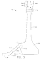
- Figure 3 is a side elevation view of high pressure turbine first stage disk assembly 102 in accordance with an exemplary embodiment of the present invention.
- Disk assembly 102 is shown in Figure 3 as a first embodiment 302 in solid lines superimposed on a second embodiment 304 in dashed lines so that differences between a profile of second embodiment 304 and a profile of first embodiment 302 are more clearly apparent.
- First embodiment 302 includes rim slot 144 having a first depth 306.
- Second embodiment 304 includes rim slot 144 that has a second depth 308.
- first depth 306 is at least partially responsible for increased stress in slot 144, which tends to shorten a life of disk assembly 102.
- disk assembly 102 By forming disk assembly 102 using second depth 308, which permits a larger slot bottom radius, stress in slot 144 is substantially reduced. However, a shallower depth of slot 144 also decreases a cross-sectional area of a cooling path in slot 144 and a reduced flow of cooling air 138 to blade 116 (shown in Figure 1 ). Because of the increased life of disk assembly 102 provided by a shallower slot 144, the erosion in cavity 148 becomes a more life limiting area than the shallower slot 144 and presents a new problem to be solved.
- cavity 148 serves to improve attenuation of air passages 142 from the expansion of hub 128 due to centrifugal and thermal loads.
- shape, position, and orientation of air passages are modified and to restore adequate cooling air pressure to blades 116 and/or 118, the area of air passages is increased.
- FIG 4 is a schematic view of air passage 142 (shown in Figure 1 ) in accordance with an exemplary embodiment of the present invention.
- air passage 142 includes a non-circular shape, for example, but not limited to an elliptical shape.
- the elliptical shape of air passage 142 includes a major axis 402 and a minor axis 404.
- Air passage 142 has a width 406 across major axis and a depth 408 across minor access 404.
- a circumferential line 410 circumscribes conical shaft connection 134 at an axial location through a center 412 of the elliptical shape of air passage 142.
- conical shaft connection 134 transfers significant torque from the high pressure turbine (HPT) to a high pressure compressor (HPC), major axis of air passage 142 is canted by an angle ⁇ with respect to circumferential line 410.
- angle ⁇ is an angle between five degrees and twenty degrees with respect to circumferential line 410.
- angle ⁇ is approximately fifteen degrees to maintain a highest stress peak proximate a center of major axis 402. This results in significant stress reduction and robustness for all operations (including the stresses due to torque) by maintaining the peak stress located on the largest radius possible and in the most advantageous position on the surface of air passage 142.
- the stress reduction obtained from newly shaped air passage 142 allowed for elimination of the shaft forward inner pocket cavity 148.
- the elliptical shape of air passage 142 is able to achieve a greater opening area than a circular opening having an increased diameter without increasing peak hole stresses unacceptably proximate air passage 142.
- the greater opening area permits an improvement in the flow circuit pressure. In combination with eliminating the deep pocket cavity 148 it would not be possible to enlarge air passage 142 as a circular hole due to a lack of space in conical shaft connection 134 proximate hub 128.
- non-circular shaped hole is sized, shaped, and oriented to act as a diffuser extension of deswirler 132 in that selecting the clocking position of a pattern of air passages 142 in relation to deswirler 132 permits control of the flow tangential mach number radially inward from air passage 142 facilitate pressure recovery.
- Figure 5A is an aftward-looking perspective view of conical shaft connection 134 (shown in Figure 1 ) including circular shaped holes 502. As illustrated in Figure 5A , holes 502 are clocked approximately two degrees with respect to deswirler clips 504, which are indicative of a position of vanes of the deswirler when installed.
- Figure 5B is an aftward perspective view of conical shaft connection 134 (shown in Figure 1 ) in accordance with an exemplary embodiment of the present invention.
- air passages 142 are elliptically-shaped passages that extend through conical shaft connection 134.
- Major axis 402 of air passages 142 are canted approximately fifteen degrees with respect to circumferential line 410.
- Air passages 142 are clocked approximately seven degrees with respect to a position of vanes in deswirler 132 when installed. Positions of a plurality of attachment clips 504 are indicative of the position of deswirler 132.
- An angle ⁇ represents an amount of the clocking position of center 412 in relation to deswirler 132. In one embodiment, angle ⁇ is between approximately three degrees and approximately fifteen degrees. In an alternative embodiment, angle ⁇ is approximately five degrees to approximately ten degrees. In the exemplary embodiment, angle ⁇ is approximately seven degrees. Setting angle ⁇ to approximately seven degrees also decreased the tangential Mach number to an acceptable value.
- the above-described embodiments of a method and system of forming a turbine disk provides a cost-effective and reliable means for providing cooling to components of a turbine engine and reducing stress in such components. More specifically, the methods and systems described herein facilitate increases a life of components of a high pressure turbine disk assembly such that a life of the assembly as a whole is increased. As a result, the methods and systems described herein facilitate forming and operating turbine engines in a cost-effective and reliable manner.
Landscapes
- Engineering & Computer Science (AREA)
- Mechanical Engineering (AREA)
- General Engineering & Computer Science (AREA)
- Turbine Rotor Nozzle Sealing (AREA)
Applications Claiming Priority (1)
| Application Number | Priority Date | Filing Date | Title |
|---|---|---|---|
| US12/324,324 US8172506B2 (en) | 2008-11-26 | 2008-11-26 | Method and system for cooling engine components |
Publications (2)
| Publication Number | Publication Date |
|---|---|
| EP2192268A2 true EP2192268A2 (fr) | 2010-06-02 |
| EP2192268A3 EP2192268A3 (fr) | 2017-05-31 |
Family
ID=41376375
Family Applications (1)
| Application Number | Title | Priority Date | Filing Date |
|---|---|---|---|
| EP09176458.9A Withdrawn EP2192268A3 (fr) | 2008-11-26 | 2009-11-19 | Méthode et système pour le refroidissement des composants de turbine à gaz |
Country Status (4)
| Country | Link |
|---|---|
| US (1) | US8172506B2 (fr) |
| EP (1) | EP2192268A3 (fr) |
| JP (1) | JP5815919B2 (fr) |
| CA (1) | CA2686192C (fr) |
Cited By (3)
| Publication number | Priority date | Publication date | Assignee | Title |
|---|---|---|---|---|
| FR3083824A1 (fr) * | 2018-07-11 | 2020-01-17 | Safran Aircraft Engines | Piece pour rotor de turbomachine d'aeronef comprenant un orifice de deshuilage de forme elliptique |
| WO2023281221A1 (fr) | 2021-07-09 | 2023-01-12 | Safran Helicopter Engines | Systeme anti-incendie pour une turbomachine comprenant des moyens de maintien d'une vitesse d'air de refroidissement et turbomachine correspondante |
| FR3125082A1 (fr) * | 2021-07-09 | 2023-01-13 | Safran Helicopter Engines | Systeme anti-incendie pour une turbomachine comprenant un diffuseur d’air de refroidissement et turbomachine correspondante |
Families Citing this family (5)
| Publication number | Priority date | Publication date | Assignee | Title |
|---|---|---|---|---|
| PL417315A1 (pl) * | 2016-05-25 | 2017-12-04 | General Electric Company | Silnik turbinowy z zawirowywaczem |
| CN109356662B (zh) * | 2018-11-27 | 2021-06-18 | 中国航发沈阳黎明航空发动机有限责任公司 | 一种航空发动机低压涡轮转子装配的工艺方法 |
| CN115013837B (zh) * | 2022-05-12 | 2023-08-18 | 中国航发四川燃气涡轮研究院 | 一种用于航空发动机燃烧室扩压器引气结构 |
| US12305535B2 (en) | 2022-10-21 | 2025-05-20 | General Electric Company | Turbine engine having a compressor with an inducer |
| US12523178B1 (en) | 2024-11-25 | 2026-01-13 | General Electric Deutschland Holding Gmbh | Compressor bleed-air boost system |
Family Cites Families (15)
| Publication number | Priority date | Publication date | Assignee | Title |
|---|---|---|---|---|
| US3950950A (en) * | 1975-05-05 | 1976-04-20 | E. I. Du Pont De Nemours And Company | Rotary Rankine engine powered electric generating apparatus |
| GB2075123B (en) * | 1980-05-01 | 1983-11-16 | Gen Electric | Turbine cooling air deswirler |
| US4674955A (en) * | 1984-12-21 | 1987-06-23 | The Garrett Corporation | Radial inboard preswirl system |
| JPH04265228A (ja) * | 1991-02-20 | 1992-09-21 | Toshiba Ceramics Co Ltd | ガラス窯フィーダー用ベンテッドチューブ |
| US5143512A (en) | 1991-02-28 | 1992-09-01 | General Electric Company | Turbine rotor disk with integral blade cooling air slots and pumping vanes |
| US5215440A (en) * | 1991-10-30 | 1993-06-01 | General Electric Company | Interstage thermal shield with asymmetric bore |
| JP2592525Y2 (ja) * | 1993-12-16 | 1999-03-24 | 三菱重工業株式会社 | シリンダライナ |
| US6561758B2 (en) | 2001-04-27 | 2003-05-13 | General Electric Company | Methods and systems for cooling gas turbine engine airfoils |
| US6540477B2 (en) * | 2001-05-21 | 2003-04-01 | General Electric Company | Turbine cooling circuit |
| US6749400B2 (en) | 2002-08-29 | 2004-06-15 | General Electric Company | Gas turbine engine disk rim with axially cutback and circumferentially skewed cooling air slots |
| US6860722B2 (en) | 2003-01-31 | 2005-03-01 | General Electric Company | Snap on blade shim |
| US7008181B2 (en) | 2003-09-04 | 2006-03-07 | General Electric Co. | Gas turbine engine air baffle for a rotating cavity |
| US7331763B2 (en) | 2005-12-20 | 2008-02-19 | General Electric Company | Turbine disk |
| US7458774B2 (en) | 2005-12-20 | 2008-12-02 | General Electric Company | High pressure turbine disk hub with curved hub surface and method |
| US7578656B2 (en) | 2005-12-20 | 2009-08-25 | General Electric Company | High pressure turbine disk hub with reduced axial stress and method |
-
2008
- 2008-11-26 US US12/324,324 patent/US8172506B2/en active Active
-
2009
- 2009-11-17 JP JP2009261461A patent/JP5815919B2/ja not_active Expired - Fee Related
- 2009-11-19 CA CA2686192A patent/CA2686192C/fr not_active Expired - Fee Related
- 2009-11-19 EP EP09176458.9A patent/EP2192268A3/fr not_active Withdrawn
Cited By (5)
| Publication number | Priority date | Publication date | Assignee | Title |
|---|---|---|---|---|
| FR3083824A1 (fr) * | 2018-07-11 | 2020-01-17 | Safran Aircraft Engines | Piece pour rotor de turbomachine d'aeronef comprenant un orifice de deshuilage de forme elliptique |
| WO2023281221A1 (fr) | 2021-07-09 | 2023-01-12 | Safran Helicopter Engines | Systeme anti-incendie pour une turbomachine comprenant des moyens de maintien d'une vitesse d'air de refroidissement et turbomachine correspondante |
| FR3125083A1 (fr) * | 2021-07-09 | 2023-01-13 | Safran Helicopter Engines | Systeme anti-incendie pour une turbomachine comprenant des moyens de maintien d’une vitesse d’air de refroidissement et turbomachine correspondante |
| FR3125082A1 (fr) * | 2021-07-09 | 2023-01-13 | Safran Helicopter Engines | Systeme anti-incendie pour une turbomachine comprenant un diffuseur d’air de refroidissement et turbomachine correspondante |
| US12385440B2 (en) | 2021-07-09 | 2025-08-12 | Safran Helicopter Engines | Fire safety system for a turbomachine comprising means for maintaining a cooling air speed and corresponding turbomachine |
Also Published As
| Publication number | Publication date |
|---|---|
| CA2686192A1 (fr) | 2010-05-26 |
| JP2010127279A (ja) | 2010-06-10 |
| JP5815919B2 (ja) | 2015-11-17 |
| US8172506B2 (en) | 2012-05-08 |
| EP2192268A3 (fr) | 2017-05-31 |
| US20100129197A1 (en) | 2010-05-27 |
| CA2686192C (fr) | 2017-04-11 |
Similar Documents
| Publication | Publication Date | Title |
|---|---|---|
| CA2686192C (fr) | Methode et systeme de refroidissement d'elements de turbine | |
| EP1965031B1 (fr) | Virole d'étanchéité | |
| EP1079074B1 (fr) | Aube statorique et stator pour une turbomachine | |
| EP2935789B2 (fr) | Ensemble de surfaces portantes avec profilage de parois d'extrémité appariées | |
| CA2645778C (fr) | Tuyere divergente de turbine | |
| US8834129B2 (en) | Turbofan flow path trenches | |
| EP2434097B1 (fr) | Aube rotorique de turbine | |
| EP2386723B1 (fr) | Agencement d'aubes directrices à géométrie variable | |
| EP1927727B1 (fr) | Aube de turbine avec tête d'aube refroidi et son procédé de refroidissement | |
| EP3722556B1 (fr) | Section de turbine à gaz ayant un contour de paroi d'extrémité non axisymétrique avec crête à mi-passage en aval | |
| EP3722555B1 (fr) | Section de turbine ayant contournage de paroi d'extrémité non axisymétrique avec crête à mi-passage | |
| EP3026212B1 (fr) | Dégagement de face de grille monobloc | |
| US20170191367A1 (en) | Variable stator vane undercut button | |
| JP2006170198A (ja) | タービン段 | |
| US10941671B2 (en) | Gas turbine engine component incorporating a seal slot | |
| US20190128126A1 (en) | Turbine blisk and method of manufacturing thereof | |
| EP1076159B1 (fr) | Ebauche d'une aube fixe et méthode pour sa formation | |
| EP3177811B1 (fr) | Compresseur d'une turbine à gaz | |
| RU2567524C2 (ru) | Система и способ для отбора рабочей текучей среды от внутреннего объема турбомашины и турбомашина, содержащая такую систему | |
| EP3904638B1 (fr) | Ensemble rotor |
Legal Events
| Date | Code | Title | Description |
|---|---|---|---|
| PUAI | Public reference made under article 153(3) epc to a published international application that has entered the european phase |
Free format text: ORIGINAL CODE: 0009012 |
|
| AK | Designated contracting states |
Kind code of ref document: A2 Designated state(s): AT BE BG CH CY CZ DE DK EE ES FI FR GB GR HR HU IE IS IT LI LT LU LV MC MK MT NL NO PL PT RO SE SI SK SM TR |
|
| AX | Request for extension of the european patent |
Extension state: BA RS |
|
| PUAL | Search report despatched |
Free format text: ORIGINAL CODE: 0009013 |
|
| AK | Designated contracting states |
Kind code of ref document: A3 Designated state(s): AT BE BG CH CY CZ DE DK EE ES FI FR GB GR HR HU IE IS IT LI LT LU LV MC MK MT NL NO PL PT RO SE SI SK SM TR |
|
| AX | Request for extension of the european patent |
Extension state: BA RS |
|
| RIC1 | Information provided on ipc code assigned before grant |
Ipc: F01D 5/08 20060101AFI20170421BHEP Ipc: F01D 25/12 20060101ALI20170421BHEP |
|
| STAA | Information on the status of an ep patent application or granted ep patent |
Free format text: STATUS: THE APPLICATION IS DEEMED TO BE WITHDRAWN |
|
| 18D | Application deemed to be withdrawn |
Effective date: 20171201 |